


DMRS的产生
简介
DMRS: Demoulation Reference Signal
DMRS is used to estimate a physical channel containing user data on only a certain part of the bandwidth. The two physical channels associated with DMRS are physical uplink shared channel (PUSCH) and physical uplink control channel (PUCCH) and DMRS is sent within them. Our focus with DMRS will be on PUSCH. Note that DMRS can be based on either Gold sequence or ZC sequence depending on the situation.
DMRS 产生
DMRS can be sent with transform precoding enabled or disabled. This means that either an additional digital fourier transform is applied to the signal before subcarrier mapping.
下面我们将对DMRS做分类:
(1) DMRS: transform precoding disabled

(2) DMRS: transform precoding enabled

(2.1) ZC sequence based DMRS

(2.2) Gold sequence based DMRS
(1) DMRS: transform precoding disabled
If transform precoding for PUSCH is disabled, the sequence r ( n ) r(n) r(n) shall be generated according to
r ( n ) = 1 2 ( 1 − 2 ⋅ c ( 2 n ) ) + j 1 2 ( 1 − 2 ⋅ c ( 2 n + 1 ) ) (1) r(n) = \frac{1}{\sqrt{2}} \left (1-2 \cdot c(2n) \right) + j \frac{1}{\sqrt{2}} \left (1-2 \cdot c(2n+1) \right) \tag {1} r(n)=21(1−2⋅c(2n))+j21(1−2⋅c(2n+1))(1)
where the pseudorandom sequence for reference signal generation is defined by a length-31 Gold sequence. The two m-sequence used to generate it for
n
=
0
,
1
,
⋯
,
M
−
1
n=0,1,\cdots,M-1
n=0,1,⋯,M−1 are formed as
x
1
(
n
+
31
)
=
(
x
1
(
n
+
3
)
+
x
1
(
n
)
)
mod
2
x
2
(
n
+
31
)
=
(
x
2
(
n
+
3
)
+
x
2
(
n
+
2
)
+
x
2
(
n
+
1
)
+
x
2
(
n
)
)
mod
2
(2)
\begin{aligned} x_1(n+31) &= \left ( x_1 (n+3) + x_1 (n) \right ) \ \ \text{mod} \ \ 2 \\ x_2(n+31) &= \left ( x_2 (n+3) + x_2 (n+2) + x_2 (n+1) + x_2 (n) \right ) \ \ \text{mod} \ \ 2 \\ \end{aligned} \tag {2}
x1(n+31)x2(n+31)=(x1(n+3)+x1(n)) mod 2=(x2(n+3)+x2(n+2)+x2(n+1)+x2(n)) mod 2(2)
where the first 31 values are initialized as
x
1
(
n
)
=
{
1
if
n
=
0
0
if
1
≤
n
≤
30
(3)
x_1(n)=\left\{ \begin{array}{cl} 1 & \text{if } \ n = 0 \\ 0 & \text{if } \ 1 \leq n \leq 30 \\ \end{array} \right. \tag {3}
x1(n)={10if n=0if 1≤n≤30(3)
∑ i = 0 30 x 2 ( i ) ⋅ 2 i = c init (4) \sum_{i=0}^{30} x_2(i) \cdot 2^i = c_{\text{init}} \tag {4} i=0∑30x2(i)⋅2i=cinit(4)
The resulting Gold sequence of length
M
M
M from these two m-sequence is defined as
c
(
n
)
=
(
x
1
(
n
+
1600
)
+
x
2
(
n
+
1600
)
)
mod
2
(5)
c(n) = \left ( x_1(n+1600) + x_2(n+1600) \right) \ \ \text{mod} \ \ 2 \tag{5}
c(n)=(x1(n+1600)+x2(n+1600)) mod 2(5)
where
c
init
c_{\text{init}}
cinit is
c
init
=
(
2
17
(
N
symb
slot
n
s
,
f
μ
+
l
+
1
)
⋅
(
2
N
I
D
n
S
C
I
D
λ
ˉ
+
1
)
+
2
17
⌊
λ
ˉ
2
⌋
+
2
N
I
D
n
S
C
I
D
λ
ˉ
+
n
ˉ
S
C
I
D
λ
ˉ
)
mod
31
(6)
c_{\text{init}} = \left ( 2^{17} \left ( N^{\text{slot}}_{\text{symb}} n^{\mu}_{s,f} + l + 1 \right) \cdot \left ( 2 N^{n^{\bar \lambda}_{SCID}}_{ID} + 1 \right) + 2^{17} \left \lfloor \frac{\bar \lambda}{2} \right \rfloor + 2 N^{n^{\bar \lambda}_{SCID}}_{ID} + \bar n^{\bar \lambda}_{SCID} \right) \ \ \text{mod} \ \ 31 \tag{6}
cinit=(217(Nsymbslotns,fμ+l+1)⋅(2NIDnSCIDλˉ+1)+217⌊2λˉ⌋+2NIDnSCIDλˉ+nˉSCIDλˉ) mod 31(6)
where
- N symb slot N^{\text{slot}}_{\text{symb}} Nsymbslot is the number of symbols per slot.
- n s , f μ n^{\mu}_{s,f} ns,fμ is the slot number within frame f f f for subcarrier spacing (SCS) μ \mu μ.
- l ∈ { 0 , 1 , ⋯ , 13 } l \in \{0,1,\cdots, 13\} l∈{0,1,⋯,13} is the OFDM symbol number within a slot.
-
n
ˉ
S
C
I
D
λ
ˉ
\bar n^{\bar \lambda}_{SCID}
nˉSCIDλˉ and
λ
ˉ
\bar \lambda
λˉ is given by
-
if the higher-layer parameter dmrs-Uplink in the DMRS-UplinkConfig IE is provided ( λ \lambda λ is the CDM group)
n ˉ S C I D λ ˉ = { n S C I D λ = 0 or λ = 2 1 − n S C I D λ = 1 \bar n^{\bar \lambda}_{SCID}=\left\{ \begin{array}{cl} n^{}_{SCID} & \lambda = 0 \text{or } \ \lambda = 2 \\ 1-n^{}_{SCID} & \lambda = 1 \\ \end{array} \right. nˉSCIDλˉ={nSCID1−nSCIDλ=0or λ=2λ=1 -
otherwise
n ˉ S C I D λ ˉ = n S C I D λ ˉ = 0 \begin{aligned} \bar n^{\bar \lambda}_{SCID} &= n^{}_{SCID} \\ \bar \lambda &= 0 \end{aligned} nˉSCIDλˉλˉ=nSCID=0
-
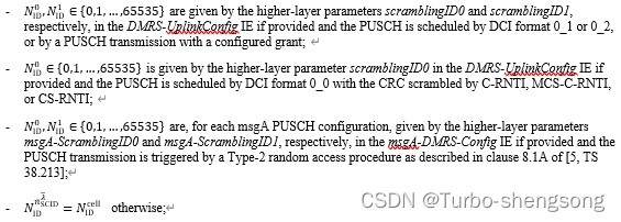
The quantity n S C I D ∈ { 0 , 1 } n^{}_{SCID} \in \{0,1\} nSCID∈{0,1} is
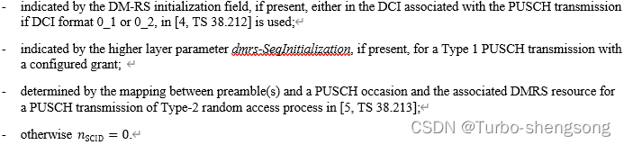
(2) DMRS: transform precoding enabled
Two types of low peak-to-average (PAPR) sequences are defined for forming reference signals in 5G NR, called type 1 and type 2. Type 1 is ZC based whereas type 2 is Gold sequence based.
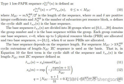
Type 1
Type 2
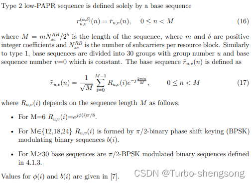
(注:上面所述的4.1.4所对应的sequence指的就是式(6)所对应的二进制序列)
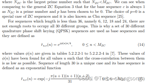
(2.1) ZC sequence based DMRS
r ( n , l ) = r u , v ( α , σ ) ( n ) , 0 ≤ n ≤ M P U S C H 2 δ − 1 (7) r(n,l) = r^{(\alpha,\sigma)}_{u,v} (n), \ \ 0 \leq n \leq \frac{M^{PUSCH}}{2^\delta}-1 \tag{7} r(n,l)=ru,v(α,σ)(n), 0≤n≤2δMPUSCH−1(7)
where α = 0 , δ = 1 \alpha=0,\delta=1 α=0,δ=1 and M P U S C H = n R B ⋅ N s c R B / 2 M^{PUSCH} = n^{RB} \cdot N^{RB}_{sc} / 2 MPUSCH=nRB⋅NscRB/2 is the scheduled bandwidth for uplink transmission expressed as a number of subcarriers,
- N s c R B N^{RB}_{sc} NscRB is the number of consecutive subcarriers per RB
- n R B n^{RB} nRB is the number of physical RBs
r u , v ( α , σ ) r^{(\alpha,\sigma)}_{u,v} ru,v(α,σ)的定义在Type 1中。
(2.2) Gold sequence based DMRS
与ZC sequence based DMRS一致,但是
r
u
,
v
(
α
,
σ
)
r^{(\alpha,\sigma)}_{u,v}
ru,v(α,σ)的定义在Type 2中
r
(
n
)
=
r
u
,
v
(
α
,
σ
)
(
n
)
,
0
≤
n
≤
M
−
1
,
M
=
M
P
U
S
C
H
2
δ
(8)
r(n) = r^{(\alpha,\sigma)}_{u,v} (n), \ \ 0 \leq n \leq M-1, \ \ M=\frac{M^{PUSCH}}{2^\delta} \tag{8}
r(n)=ru,v(α,σ)(n), 0≤n≤M−1, M=2δMPUSCH(8)
另外,当
M
≥
30
M\geq 30
M≥30时,Gold sequence based DMRS会利用到式(5)所述的Gold Pseudorandom sequence,此时序列的初始化与式(6)略有不同,表示为
c
init
=
(
2
17
(
N
symb
slot
n
s
,
f
μ
+
l
+
1
)
⋅
(
2
N
I
D
n
S
C
I
D
+
1
)
+
2
N
I
D
n
S
C
I
D
+
n
S
C
I
D
)
mod
2
31
(9)
c_{\text{init}} = \left ( 2^{17} \left ( N^{\text{slot}}_{\text{symb}} n^{\mu}_{s,f} + l + 1 \right) \cdot \left ( 2 N^{n^{}_{SCID}}_{ID} + 1 \right) + 2 N^{n^{}_{SCID}}_{ID} + n^{}_{SCID} \right) \ \ \text{mod} \ \ 2^{31} \tag{9}
cinit=(217(Nsymbslotns,fμ+l+1)⋅(2NIDnSCID+1)+2NIDnSCID+nSCID) mod 231(9)
where
- N symb slot N^{\text{slot}}_{\text{symb}} Nsymbslot is the number of symbols per slot.
- n s , f μ n^{\mu}_{s,f} ns,fμ is the slot number within frame f f f for subcarrier spacing (SCS) μ \mu μ.
- l ∈ { 0 , 1 , ⋯ , 13 } l \in \{0,1,\cdots, 13\} l∈{0,1,⋯,13} is the OFDM symbol number within a slot.
- n S C I D ∈ { 0 , 1 } n_{SCID} \in \{0,1\} nSCID∈{0,1} is the scrambling identiy
- N I D n S C I D ∈ { 0 , 1 , ⋯ , 65535 } N^{n^{}_{SCID}}_{ID} \in \{0,1,\cdots, 65535\} NIDnSCID∈{0,1,⋯,65535} is the physical layer cell identity.
PUSCH
Physical uplink shared channel is used for transmission of the uplink shared channel and layer 1 and layer 2 control infromation. Processing of data to resource blocks in PUSCH consists of 7 steps:
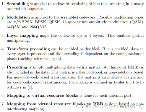
Mapping to physical resources
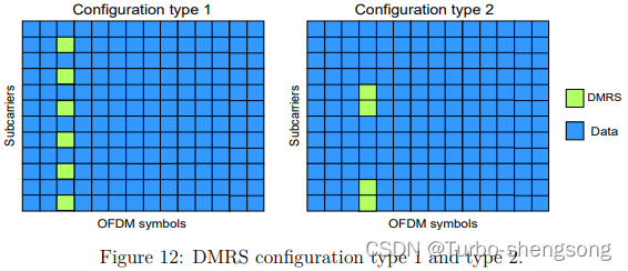
DMRS Configuration
type1: define 6 subcarriers per PRB and they are set to every other subcarrier.
type2: disignate 4 subcarriers per PRB and they are organized to be two groups of two subcarriers.
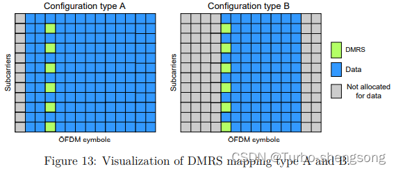
DMRS mapping
type A: the first DMRS is located in the second or third OFDM symbol. Type A is good for transmission in which the data fills most of the slot.
type B: the first DMRS is located in the first symbol of the data allocation. Type B is good for transmissions where data can be anywhere in the slot.
备注:MATLAB 5G Toolbox中有产生DMRS的相关函数,相关函数见链接NR PUSCH Resource Allocation and DM-RS and PT-RS Reference Signals以及nrPUSCHDMRS
参考
[1] Essi Rantanen. Study of the Statistical Properties of SRS and DMRS for Machine Learning in 5G. Master’s thesis, Aalto University. School of Science, 2021.
[2] 3GPP TS 38.211 v17.0.0 (2021-12)


 7278
7278


 被折叠的 条评论
为什么被折叠?
被折叠的 条评论
为什么被折叠?
 到【灌水乐园】发言


