


填充
实体填充(SolidFill)
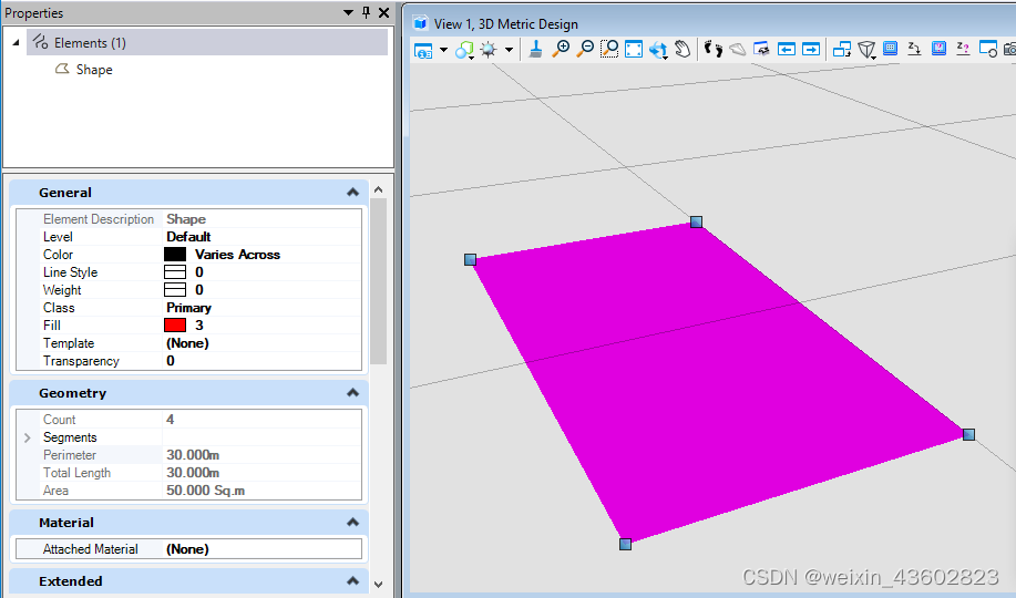
我们可以使用AddSolidFill()对元素进行实体填充,其中,第一个值为填充颜色索引值,与MicroStation中的颜色索引对应
public static void CmdElementSolidFill(string unparsed)
{
    DgnModel dgnModel = Session.Instance.GetActiveDgnModel();//定义当前激活的模型空间
    double uorPerMas = Session.Instance.GetActiveDgnModel().GetModelInfo().UorPerMaster;//获取主单位与分辨率单位的比值

    DPoint3d p1 = new DPoint3d(5 * uorPerMas, 5 * uorPerMas, 0);//定义形元素端点
    DPoint3d p2 = new DPoint3d(10 * uorPerMas, 5 * uorPerMas, 0);
    DPoint3d p3 = new DPoint3d(10 * uorPerMas, -5 * uorPerMas, 0);
    DPoint3d p4 = new DPoint3d(5 * uorPerMas, -5 * uorPerMas);
    DPoint3d[] pos = { p1, p2, p3, p4 };//将端点添加到端点集中

    ShapeElement shape = new ShapeElement(dgnModel, null, pos);//使用端点集定义形元素
    shape.AddSolidFill(3,true);
    /*
     * 对支持的元素添加实体填充
     * fillColor:填充颜色,若与边框颜色一致则输入null
     * alwaysFilled:是否遵守“填充视图”属性
     */

    shape.AddToModel();//将形元素写入模型
}
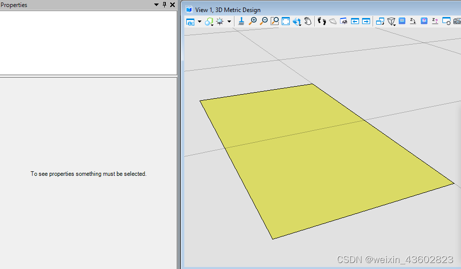
我们可以看到,生成元素的填充已经被索引为3(红色)的实体填充
梯度填充(GradientFill)
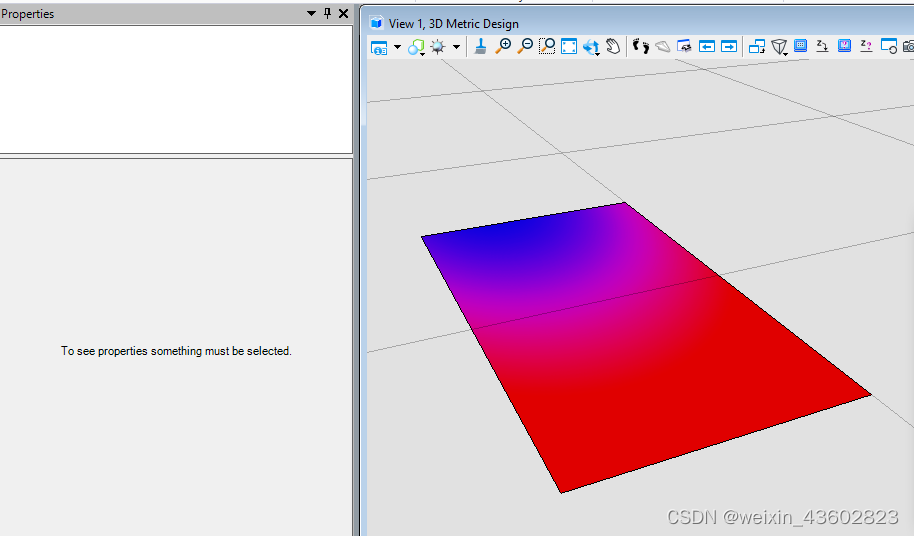
我们可以使用AddGradientFill()对元素进行渐变填充,在附加填充之前,首先需要对梯度填充属性进行定义,可定义的属性包括渐变颜色,渐变程度,填充角度,填充色调等
public static void CmdElementGradientFill(string unparsed)
{
    DgnModel dgnModel = Session.Instance.GetActiveDgnModel();//定义当前激活的模型空间
    double uorPerMas = Session.Instance.GetActiveDgnModel().GetModelInfo().UorPerMaster;//获取主单位与分辨率单位的比值

    DPoint3d p1 = new DPoint3d(5 * uorPerMas, 5 * uorPerMas, 0);//定义形元素端点
    DPoint3d p2 = new DPoint3d(10 * uorPerMas, 5 * uorPerMas, 0);
    DPoint3d p3 = new DPoint3d(10 * uorPerMas, -5 * uorPerMas, 0);
    DPoint3d p4 = new DPoint3d(5 * uorPerMas, -5 * uorPerMas);
    DPoint3d[] pos = { p1, p2, p3, p4 };//将端点添加到端点集中

    ShapeElement shape = new ShapeElement(dgnModel, null, pos);//使用端点集定义形元素

    GradientSymbology gSymb = new GradientSymbology();//定义梯度填充设置集
    RgbColorDef[] colors = new RgbColorDef[2];//定义颜色容器
    double[] values = new double[2];//定义储存填充程度容器
    colors[0] = new RgbColorDef(255, 0, 0);//设置颜色定义
    colors[1] = new RgbColorDef(0, 0, 255);
    values[0] = 0.0;//设置填充程度定义
    values[1] = 1.0;
    gSymb.Mode = GradientMode.None;//设置梯度填充模式
    gSymb.Angle = 10.0;//设置梯度填充角度
    gSymb.Tint = 2.0;//设置梯度填充色调
    gSymb.Shift = 3.0;//设置梯度填充转换
    gSymb.SetKeys(colors, values);//将填充颜色与程度添加到设置集

    shape.AddGradientFill(gSymb);//对形元素添加渐变填充
    shape.AddToModel();//将形元素导入模型空间
}
图案填充(PatternFill)
当我们需要使用图案进行填充,或者使用二维进行出图操作时,往往需要使用特点的填充图案指代材质。在这个过程中可能就会涉及到需要与CAD中的图案填充效果保持一致,那么就需要使用图案填充实现。在属性中,我们不仅可以规定填充颜色,间距,还可以通过.pat文件中的信息构建出我们所需要的图案填充
关于图案填充的问题
public static void CmdElementPatternFill(string unparsed)
{
    DgnModel dgnModel = Session.Instance.GetActiveDgnModel();//定义当前激活的模型空间
    double uorPerMas = Session.Instance.GetActiveDgnModel().GetModelInfo().UorPerMaster;//获取主单位与分辨率单位的比值

    DPoint3d p1 = new DPoint3d(5 * uorPerMas, 5 * uorPerMas, 0);//定义形元素端点
    DPoint3d p2 = new DPoint3d(10 * uorPerMas, 5 * uorPerMas, 0);
    DPoint3d p3 = new DPoint3d(10 * uorPerMas, -5 * uorPerMas, 0);
    DPoint3d p4 = new DPoint3d(5 * uorPerMas, -5 * uorPerMas);
    DPoint3d[] pos = { p1, p2, p3, p4 };//将端点添加到端点集中

    ShapeElement shape = new ShapeElement(dgnModel, null, pos);//使用端点集定义形元素

    PatternParams param = new PatternParams();//初始化模式定义
    param.HoleStyle = PatternParamsHoleStyleType.Normal;//设置孔洞样式为普通
    param.Color = 5;//设置颜色为紫色(索引为5)
    param.PrimarySpacing = 0.1*uorPerMas;//设置线段间隔距离为0.1m
    DwgHatchDefLine defLine = new DwgHatchDefLine();//初始化DWG填充定义
    DwgHatchDefLine[] defLines = { defLine };//将DWG填充定义放入其数组中

    shape.AddPattern(param, defLines, 0);//对形元素添加图案填充
    shape.AddToModel();//将形元素导入模型空间
}
材质填充(MaterialFill)
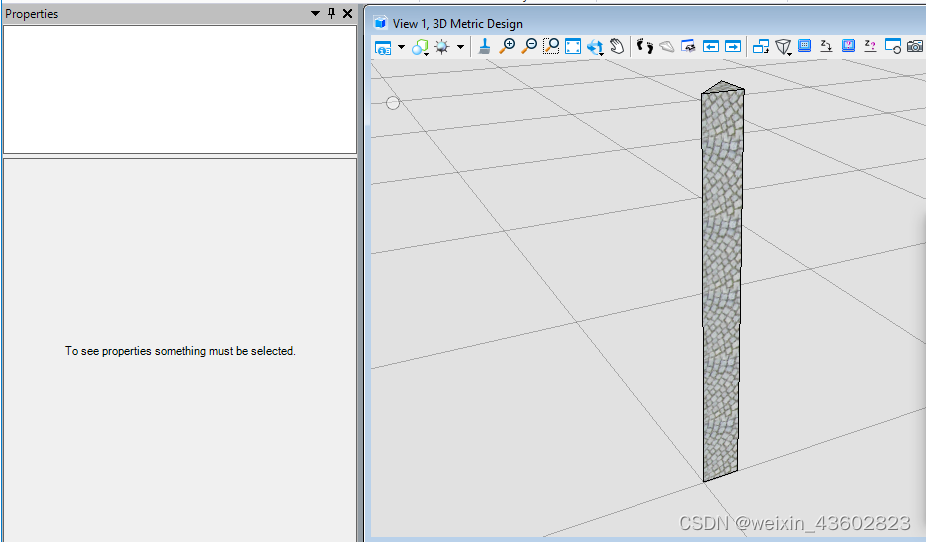
当我们需要对元素进行材质填充时,需要首先找到存放该材质的材质表和材质图表,最后将材质挂接到元素上,实现材质填充的最终效果
public static void CmdElementMaterialFill(string unparsed)
{
    DgnFile dgnFile = Session.Instance.GetActiveDgnFile();//定义当前激活的文件信息
    DgnModel dgnModel = Session.Instance.GetActiveDgnModel();//定义当前激活的模型空间
    double uorPerMas = Session.Instance.GetActiveDgnModel().GetModelInfo().UorPerMaster;//获取主单位与分辨率单位的比值

    MaterialTable matTbl = new MaterialTable(dgnFile);//定义材料表
    matTbl.Name = "MyMaterialTable";//定义材料表名称
    PaletteInfo[] palInfo = MaterialManager.GetPalettesInSearchPath("MS_MATERIAL");//从MS_MATERIAL的环境变量定义路径下读取材料图表
    if (palInfo.Length < 1)//判断是否获取到材料图表
    {
        MessageCenter.Instance.ShowInfoMessage("Can't get palette", null, true);//输出错误信息
        return;//返回
    }
    for (int i = 0; i < palInfo.Count(); i++)//遍历材料图表
    {
        if (palInfo[i].Name == "lightwidgets")//判断材料图表是否名为lightwidgets
        {
            matTbl.AddPalette(palInfo[i]);//添加材料图表至材料表
            break;//跳出循环
        }
        else if (i == palInfo.Count() - 1)//若未找到名为lightwidgets的材料图表
        {
            MessageCenter.Instance.ShowErrorMessage("Can't find material lib named lightwidgets, please check",
                                                    "Can't find material lib named lightwidgets, please check",
                                                    true);//输出错误信息
        }
    }
    MaterialManager.SetActiveTable(matTbl, dgnModel);//设置当前材料表为激活图表
    MaterialManager.SaveTable(matTbl);//保存材料表

    MaterialId id = new MaterialId("Pavers BC2");//查找名为Pavers BC2的材料
    DPoint3d[] pos = { DPoint3d.Zero, new DPoint3d(uorPerMas, 0, 0), new DPoint3d(uorPerMas, uorPerMas, 0) };//定义坐标数组
    ShapeElement shape = new ShapeElement(Session.Instance.GetActiveDgnModel(), null, pos);//定义形元素的实例

    SurfaceOrSolidElement solid = SolidElement.CreateProjectionElement(dgnModel, null, shape, new DPoint3d(1000, 0, 0),
                                                                        new DVector3d(0, 0, 10*uorPerMas), DTransform3d.Identity, true);//定义拉伸实体元素
    MaterialPropertiesExtension propertiesExtension = MaterialPropertiesExtension.GetAsMaterialPropertiesExtension(solid);//为拉伸实体元素设置材料属性
    propertiesExtension.AddMaterialAttachment(id);//添加嵌入的材料信息
    propertiesExtension.StoresAttachmentInfo(id);//保存拉伸实体元素的材料信息
    propertiesExtension.AddToModel();//将拉伸实体写入模型
}
在本案例中,我们需要挂接名为Pavers BC2的材质,因此我们需要首先找到其他所在的材料图表——lightwidgets,然后在图表中根据名称获得。材质图表需要放置在环境变量MS_MATERIAL指定的路径下才可被成功获取
透明度(Transpancy)
当我们需要做出类似透视效果或者机制时,但是不想让外部构件直接隐藏,体现内外部构件的相互关系,此时可能会需要将外部构件的透明度提高
public static void CmdChangeElementTranspancy(string unparsed)
{
    DgnModel dgnModel = Session.Instance.GetActiveDgnModel();//定义当前激活的模型空间
    double uorPerMas = Session.Instance.GetActiveDgnModel().GetModelInfo().UorPerMaster;//获取主单位与分辨率单位的比值

    DPoint3d p1 = new DPoint3d(5 * uorPerMas, 5 * uorPerMas, 0);//定义形元素端点
    DPoint3d p2 = new DPoint3d(10 * uorPerMas, 5 * uorPerMas, 0);
    DPoint3d p3 = new DPoint3d(10 * uorPerMas, -5 * uorPerMas, 0);
    DPoint3d p4 = new DPoint3d(5 * uorPerMas, -5 * uorPerMas);
    DPoint3d[] pos = { p1, p2, p3, p4 };//将端点添加到端点集中

    ShapeElement shape = new ShapeElement(dgnModel, null, pos);//使用端点集定义形元素

    ElementPropertiesSetter setter = new ElementPropertiesSetter();//用于修改元素属性
    setter.SetColor((uint)4);//设置元素颜色索引为4
    setter.SetTransparency(0.5);//设置透明度为50
    setter.Apply(shape);//将属性修改应用于形元素

    shape.AddToModel();//将形元素写入模型空间
}
在本案例中,首先将形元素的颜色索引值设置为4(黄色),然后对透明度进行调整。需要说明的是,ElementPropertiesSetter不仅不可修改元素颜色,透明度,还可以对字体,图层,线形样式等多种属性进行设置调整


 1861
1861

 被折叠的 条评论
为什么被折叠?
被折叠的 条评论
为什么被折叠?
 到【灌水乐园】发言


