


【前言】 本文版权属于GiantPandaCV,未经允许,请勿转载!
最近在学neon汇编加速,由于此前OD任务发现在检测后处理部分使用OpenCV较为占用资源且耗时,遂尝试使用NEON做后处理绘框,以达到加速并降低CPU资源消耗的目的。
一、实现思路
假设对一张Mat图像进行操作(其实也不仅仅是Mat对象,理论上只要知道图像通道的首指针即可),在ARM端使用NEON instrinc指令集里实现一个后处理绘框的功能,可以简单罗列成以下几步:
1. 定义参数: 首先确定图像的宽度和高度,图像的首地址指针,以及边界(边框)的厚度。
2. 向量寄存器加载: 使用NEON的加载指令从内存中加载像素数据到向量寄存器中。
3. 处理上下边框:
- 对于顶部边界,遍历整个第一行的像素,并使用NEON的存储指令将特定颜色值写回到这些位置(比如想绘制的是绿框,那么需要将B通道的绘框元素数据更改为0,G通道为255,R通道为0)。
- 同样地,对于底部边界,遍历最后一行的像素并执行相同的操作。
4.处理左右边框:
这个稍微复杂一些,因为需要处理每一行的开始和结束位置。一种方法是使用循环,每次处理一行,然后更新寄存器中的值以反映特定颜色。我们可以使用NEON的广播指令来创建一个包含特定颜色所有分量的向量,然后使用存储指令将其写入到图像的左侧和右侧边界。
5.边框优化:
由于很多检测框的宽度很难保证一定是SIMD WIDTH的倍数,这就造成了在绘图时一些不必要的麻烦,举个例子,假设检测框的width是97,SIMD WIDTH的长度是16(一次性处理16个元素的向量寄存器),那么97/16=6······1,刚好多出了1个pixel,此时需要某些处理措施规避这种情况。
二、实现过程
2.1 定义参数
首先确定图像的宽度和高度,本次测试所获得的检测框均由这篇博文中的end2end模型中获得【1】,也就是在绘框前,我们会得到一个vector数组,均为通过nms获得的检测框,这个数组数据排列格式如下:

一个box对应四个元素,其实box是按照obj的score排列,但为了方便讲解,我们假设他是按从左到右顺序排列,由于测试的图片均为COCO2017 Val中的数据,图片尺寸中值远大于320,为了美观,此篇博文默认绘框边界(边框)的厚度为2,也就是占满2个pixel。
函数定义如下:
void neon_rectangle_blod(uint8_t *img, uint16_t img_step, uint16_t x, uint16_t y, uint16_t w, uint16_t h, uint8_t blue, uint8_t green, uint8_t red)
函数形参解释: ∗ i m g *img ∗img为图像首指针, i m g s t e p img step imgstep指图像的width, x , y x,y x,y指检测框左上角, w , h w,h w,h指检测框的宽高, b l u e , g r e e n , r e d blue, green, red blue,green,red指三色通道需要填充的数值。
2.2 向量寄存器加载
这一步需要将图像BGR通道元素加载到寄存器,由于图像一般为uint8格式,这里可以使用最大的寄存器,把位宽拉满,也就是一次性操作16个元素,调用NEON instrinc中的vld3q_u8加载图像BGR数据到uint8x16x3_t寄存器中,再将单个通道的数据分发到到单个uint8x16_t寄存器中,伪代码如下:
// 假设img是指向图像BGR数据的指针
uint8x16x3_t bgr_data = vld3q_u8((uint8_t *) img);

// 分别将BGR通道的数据分发到单独的uint8x16_t寄存器
uint8x16_t reg_b = bgr_data.val[0]; // 蓝色通道
uint8x16_t reg_g = bgr_data.val[1]; // 绿色通道
uint8x16_t reg_r = bgr_data.val[2]; // 红色通道

// 后续对每个通道进行单独的操作
......
2.3 处理上下边框
我们需要定位到上下边框的起始位置,获取起始位置的地址,再将地址往后以16个pixel为一个SIMD_WIDTH塞入寄存器,将寄存器中的B,G,R通道进行向量赋值,表示一次性处理16个数据流位宽,代码如下:
// 绘制矩形的上下边界
    for (uint16_t i = 0; i < w; i += 16)
    {
        // 计算当前行的起始地址
        uint8_t *top_row1 = img + (y * img_step + x + i) * 3;
        uint8_t *bottom_row1 = img + ((y + h) * img_step + x + i) * 3;

        // 使用NEON指令集并行加载和存储颜色
        uint8x16x3_t pixels_top1 = vld3q_u8(top_row1);
        uint8x16x3_t pixels_bottom1 = vld3q_u8(bottom_row1);

        // 绘制顶部和底部线条
        pixels_top1.val[0] = neon_color_b; // 蓝色通道
        pixels_top1.val[1] = neon_color_g; // 绿色通道
        pixels_top1.val[2] = neon_color_r; // 红色通道

        pixels_bottom1.val[0] = neon_color_b;
        pixels_bottom1.val[1] = neon_color_g;
        pixels_bottom1.val[2] = neon_color_r;

        vst3q_u8(top_row1, pixels_top1);
        vst3q_u8(bottom_row1, pixels_bottom1);

        // 计算当前行的起始地址
        uint8_t *top_row2 = img + ((y + 1) * img_step + x + i) * 3;
        uint8_t *bottom_row2 = img + ((y + h - 1) * img_step + x + i) * 3;

        // 使用NEON指令集并行加载和存储颜色
        uint8x16x3_t pixels_top2 = vld3q_u8(top_row2);
        uint8x16x3_t pixels_bottom2 = vld3q_u8(bottom_row2);

        // 绘制顶部和底部线条
        pixels_top2.val[0] = neon_color_b; // 蓝色通道
        pixels_top2.val[1] = neon_color_g; // 绿色通道
        pixels_top2.val[2] = neon_color_r; // 红色通道

        pixels_bottom2.val[0] = neon_color_b;
        pixels_bottom2.val[1] = neon_color_g;
        pixels_bottom2.val[2] = neon_color_r;

        vst3q_u8(top_row2, pixels_top2);
        vst3q_u8(bottom_row2, pixels_bottom2);
    }
2.4 处理左右边框
这里就有点难受了,因为是ARM架构通用的汇编,不像一些厂家有专门处理竖直方向的寄存器或者额外的硬件加速模块,所以这一步只能老老实实一个pixel一个pixel的去涂,因此和OpenCV的处理方式没有太大差异,代码如下:
// 绘制矩形的左右边界
    for (uint16_t j = 0; j < h; j++)
    {
        // 计算当前列的起始地址
        uint8_t *left_col1 = img + ((y + j) * img_step + x) * 3;
        uint8_t *right_col1 = img + ((y + j) * img_step + (x + w)) * 3;
        // 设置左边和右边列的颜色
        left_col1[0] = right_col1[0] = blue;
        left_col1[1] = right_col1[1] = green;
        left_col1[2] = right_col1[2] = red;

        // 计算当前列的起始地址
        uint8_t *left_col2 = img + ((y + j) * img_step + x + 1) * 3;
        uint8_t *right_col2 = img + ((y + j) * img_step + (x + w) - 1) * 3;
        // 设置左边和右边列的颜色
        left_col2[0] = right_col2[0] = blue;
        left_col2[1] = right_col2[1] = green;
        left_col2[2] = right_col2[2] = red;
    }
2.5 优化边框
这里提供一种思路,既然没办法确保检测框的宽度刚好是SIMD_WIDTH的倍数,那我们就将宽度扩充或者减小到SIMD_WIDTH的倍数,但为了美观处理,不管是扩充还是减小宽度,我们都离不开一个操作,那就是中心对齐,以扩宽为例,如下图所示:

那么,就有很好的方式去应对这种情况,我们假设检测框的width对SIMD_WIDTH进行mod操作,如果余数小于
S
I
M
D
‘
W
I
D
T
H
/
2
SIMD_`WIDTH/2
SIMD‘WIDTH/2,对检测框width进行缩小操作,反之,则进行扩充操作,代码如下:
void check_point(int *x1, int *x2, int nstride)
{
    int mod, w, xc, nw;
    w = *x2 - *x1;
    xc = *x1 + (int)(w / 2);
    mod = w % nstride;
    if (mod > (nstride / 2))
    {
        *x1 = xc - (int)((w + nstride - mod) / 2);
        *x2 = xc + (int)((w + nstride - mod) / 2);
    }
    else
    {
        nw = w - mod;
        *x1 = xc - int(nw / 2);
        *x2 = xc + int(nw / 2);
    }
}
三、测试结果
测试机器为4+32内存的树莓派4B,共带有4颗A72核,我们分别使用NEON和OpenCV作为【1】中end2end模型出框后的后处理绘框函数,测试数据为COCO2017 Val数据集,将两个程序用taskset -c先绑定在编号为0的核上,得出两者在处理5000张图的处理速度差异,如下所示:
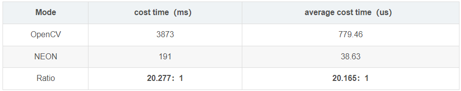
其中,cost time为推理完5000张图的所有耗时,单位为ms,average cost time为处理单张图片的耗时,单位为us,我们可以看到,在单个A72上,NEON实现的绘框函数要比OpenCV快了20倍左右。
此外,OpenCV的强大源于多核并行,为了能更加客观且全面的测试出两者的性能差异,我们在OpenCV版本的基础上,不断增加核进行测试,得出以下测试图例:

图中P/ms表示1ms能处理多少图,越高表示每毫秒处理图越多,单图绘框速度越快,从图可以看出,单核运行的NEON绘框的速度依旧稳稳碾压多核并行的OpenCV。
OpenCV绘框效果如下:

NEON汇编绘框效果如下:

四、完整代码
void check_point(int *x1, int *x2, int nstride)
{
    int mod, w, xc, nw;
    w = *x2 - *x1;
    xc = *x1 + (int)(w / 2);
    mod = w % nstride;
    if (mod > (nstride / 2))
    {
        *x1 = xc - (int)((w + nstride - mod) / 2);
        *x2 = xc + (int)((w + nstride - mod) / 2);
    }
    else
    {
        nw = w - mod;
        *x1 = xc - int(nw / 2);
        *x2 = xc + int(nw / 2);
    }
}

void neon_rectangle_blod(uint8_t *img, uint16_t img_step, uint16_t x, uint16_t y, uint16_t w, uint16_t h, uint8_t blue, uint8_t green, uint8_t red)
{
    // 创建一个全1的8位向量,用于绘制矩形的颜色
    uint8x16_t neon_color_b = vdupq_n_u8(blue);
    uint8x16_t neon_color_g = vdupq_n_u8(green);
    uint8x16_t neon_color_r = vdupq_n_u8(red);

    // 绘制矩形的上下边界
    for (uint16_t i = 0; i < w; i += 16)
    {
        // 计算当前行的起始地址
        uint8_t *top_row1 = img + (y * img_step + x + i) * 3;
        uint8_t *bottom_row1 = img + ((y + h) * img_step + x + i) * 3;

        // 使用NEON指令集并行加载和存储颜色
        uint8x16x3_t pixels_top1 = vld3q_u8(top_row1);
        uint8x16x3_t pixels_bottom1 = vld3q_u8(bottom_row1);

        // 绘制顶部和底部线条
        pixels_top1.val[0] = neon_color_b; // 蓝色通道
        pixels_top1.val[1] = neon_color_g; // 绿色通道
        pixels_top1.val[2] = neon_color_r; // 红色通道

        pixels_bottom1.val[0] = neon_color_b;
        pixels_bottom1.val[1] = neon_color_g;
        pixels_bottom1.val[2] = neon_color_r;

        vst3q_u8(top_row1, pixels_top1);
        vst3q_u8(bottom_row1, pixels_bottom1);

        // 计算当前行的起始地址
        uint8_t *top_row2 = img + ((y + 1) * img_step + x + i) * 3;
        uint8_t *bottom_row2 = img + ((y + h - 1) * img_step + x + i) * 3;

        // 使用NEON指令集并行加载和存储颜色
        uint8x16x3_t pixels_top2 = vld3q_u8(top_row2);
        uint8x16x3_t pixels_bottom2 = vld3q_u8(bottom_row2);

        // 绘制顶部和底部线条
        pixels_top2.val[0] = neon_color_b; // 蓝色通道
        pixels_top2.val[1] = neon_color_g; // 绿色通道
        pixels_top2.val[2] = neon_color_r; // 红色通道

        pixels_bottom2.val[0] = neon_color_b;
        pixels_bottom2.val[1] = neon_color_g;
        pixels_bottom2.val[2] = neon_color_r;

        vst3q_u8(top_row2, pixels_top2);
        vst3q_u8(bottom_row2, pixels_bottom2);
    }

    // 绘制矩形的左右边界
    for (uint16_t j = 0; j < h; j++)
    {
        // 计算当前列的起始地址
        uint8_t *left_col1 = img + ((y + j) * img_step + x) * 3;
        uint8_t *right_col1 = img + ((y + j) * img_step + (x + w)) * 3;
        // 设置左边和右边列的颜色
        left_col1[0] = right_col1[0] = blue;
        left_col1[1] = right_col1[1] = green;
        left_col1[2] = right_col1[2] = red;

        // 计算当前列的起始地址
        uint8_t *left_col2 = img + ((y + j) * img_step + x + 1) * 3;
        uint8_t *right_col2 = img + ((y + j) * img_step + (x + w) - 1) * 3;
        // 设置左边和右边列的颜色
        left_col2[0] = right_col2[0] = blue;
        left_col2[1] = right_col2[1] = green;
        left_col2[2] = right_col2[2] = red;
    }
}
五、总结
本篇博文主要讲述后处理绘框的汇编实现方式,在树莓派上的单核以及多核A72上都实现了加速,但时间关系未于其他开发板做比较,从去年开始,似乎4大+4小变成了业界主流,既4颗A76+4颗A57或者4颗A76+4颗A53,ARM端CPU算力要远远强过四颗A72,至于这种汇编实现方式,在这些开发板上能加速多少,确实不好说,有兴趣的朋友可以用这几十行代码去测试下~
六、参考
[1] https://zhuanlan.zhihu.com/p/672633849
[2] https://zhuanlan.zhihu.com/p/698551682
[3] https://developer.arm.com/documentation/


 407
407


 被折叠的 条评论
为什么被折叠?
被折叠的 条评论
为什么被折叠?
 到【灌水乐园】发言


