


文章目录
一、LCD
LCD ( Liquid Crystal Display 的简称)液晶显示器。LCD 的构造是在两片平行的玻璃基板当中放置液晶盒,下基板玻璃上设置TFT(薄膜晶体管),上基板玻璃上设置彩色滤光片,通过TFT上的信号与电压改变来控制液晶分子的转动方向,从而达到控制每个像素点偏振光出射与否而达到显示目的。LCD已经替代CRT成为主流,价格也已经下降了很多,并已充分普及。
二、看TM043NDH02-40–LCD手册
1.描述
用的LCD的型号是TM043NDH02-40
![[外链图片转存失败,源站可能有防盗链机制,建议将图片保存下来直接上传(img-9BoiKjRK-1645452299062)(C:\Users\Jin\AppData\Roaming\Typora\typora-user-images\image-20220221185301169.png)]](https://img-blog.csdnimg.cn/26707c90d76f4da3939290e9833ed16e.png?x-oss-process=image/watermark,type_d3F5LXplbmhlaQ,shadow_50,text_Q1NETiBARVBDQ2Nj,size_20,color_FFFFFF,t_70,g_se,x_16)
2.信号接口
![[外链图片转存失败,源站可能有防盗链机制,建议将图片保存下来直接上传(img-0TxkvNSz-1645452299063)(C:\Users\Jin\AppData\Roaming\Typora\typora-user-images\image-20220221185716552.png)]](https://img-blog.csdnimg.cn/40a876a523af48988a8293fb660689a1.png?x-oss-process=image/watermark,type_d3F5LXplbmhlaQ,shadow_50,text_Q1NETiBARVBDQ2Nj,size_20,color_FFFFFF,t_70,g_se,x_16)
![[外链图片转存失败,源站可能有防盗链机制,建议将图片保存下来直接上传(img-RbZSynX9-1645452299064)(C:\Users\Jin\AppData\Roaming\Typora\typora-user-images\image-20220221185726725.png)]](https://img-blog.csdnimg.cn/26061960eb1241798e16d938f7347378.png?x-oss-process=image/watermark,type_d3F5LXplbmhlaQ,shadow_50,text_Q1NETiBARVBDQ2Nj,size_20,color_FFFFFF,t_70,g_se,x_16)
| 信号 | 位宽 | 说明 |
|---|---|---|
| R | 8 | 红基色 |
| G | 8 | 绿基色 |
| B | 8 | 蓝基色 |
| DCLK | 串行时钟 | |
| DISP | 显示信号 | |
| HSYNC | 行同步信号 | |
| VSYNC | 场同步信号 | |
| DE | 数据有效 |
3.LCD模块图
![[外链图片转存失败,源站可能有防盗链机制,建议将图片保存下来直接上传(img-tdwv68c7-1645452299064)(C:\Users\Jin\AppData\Roaming\Typora\typora-user-images\image-20220221204519672.png)]](https://img-blog.csdnimg.cn/2d6c12cd4df1422d83814bd5221f4bc7.png?x-oss-process=image/watermark,type_d3F5LXplbmhlaQ,shadow_50,text_Q1NETiBARVBDQ2Nj,size_20,color_FFFFFF,t_70,g_se,x_16)
4.LCD时序
![[外链图片转存失败,源站可能有防盗链机制,建议将图片保存下来直接上传(img-d7G0Hf4m-1645452299064)(C:\Users\Jin\AppData\Roaming\Typora\typora-user-images\image-20220221190121838.png)]](https://img-blog.csdnimg.cn/7202f5b3f84c4a9d9a46ddcc1ee972fd.png?x-oss-process=image/watermark,type_d3F5LXplbmhlaQ,shadow_50,text_Q1NETiBARVBDQ2Nj,size_20,color_FFFFFF,t_70,g_se,x_16)
同步脉冲a:sync
显示后沿b:back porch
显示时序段c:display
显示前沿d:font porch
5.LCD原理图
![[外链图片转存失败,源站可能有防盗链机制,建议将图片保存下来直接上传(img-FSvYuuqS-1645452299064)(C:\Users\Jin\AppData\Roaming\Typora\typora-user-images\image-20220221204329954.png)]](https://img-blog.csdnimg.cn/eb5c40f1384341328d88ec44991d661e.png?x-oss-process=image/watermark,type_d3F5LXplbmhlaQ,shadow_50,text_Q1NETiBARVBDQ2Nj,size_12,color_FFFFFF,t_70,g_se,x_16)
三、代码部分
1.lcd_driver.v
module lcd_driver(
    input				clk		,
    input				rst_n	,
    input   [23:0]      rgb_data,
    output  [7:0]       lcd_r   ,
    output  [7:0]       lcd_g   ,
    output  [7:0]       lcd_b   ,
    output              lcd_vsync,
    output              lcd_hsync,
    output              lcd_dclk,
    output              lcd_disp,
    output              lcd_de  ,
    output  [10:0]      pixel_x ,
    output  [9:0]       pixel_y
);

// 场
parameter   V_SYNC      = 2     ,
            V_BKPORCH   = 33    ,
            V_DISPLAY   = 480   ,
            V_FTPORCH   = 10    ,
            V_ALL       = V_SYNC + V_BKPORCH + V_DISPLAY + V_FTPORCH;
// 行
parameter   H_SYNC      = 96    ,
            H_BKPORCH   = 48    ,
            H_DISPLAY   = 640   ,
            H_FTPORCH   = 16    ,
            H_ALL       = H_SYNC + H_BKPORCH + H_DISPLAY + H_FTPORCH;

// 场帧长计数器
reg     [10:0]      cnt_v;
wire                add_cnt_v;
wire                end_cnt_v;

// 行帧长计数器
reg     [10:0]      cnt_h;
wire                add_cnt_h;
wire                end_cnt_h;

// 行帧长计数器
always @(posedge clk or negedge rst_n)begin
   if(!rst_n)begin
        cnt_h <= 0;
    end
    else if(add_cnt_h)begin
            if(end_cnt_h)begin
                cnt_h <= 0;
            end
            else begin
                cnt_h <= cnt_h + 1;
            end
    end
   else  begin
       cnt_h <= cnt_h;
    end
end

assign add_cnt_h = 1'b1;
assign end_cnt_h = add_cnt_h && cnt_h == H_ALL - 1;

// 场帧长计数器
always @(posedge clk or negedge rst_n)begin
   if(!rst_n)begin
        cnt_v <= 0;
    end
    else if(add_cnt_v)begin
            if(end_cnt_v)begin
                cnt_v <= 0;
            end
            else begin
                cnt_v <= cnt_v + 1;
            end
    end
   else  begin
       cnt_v <= cnt_v;
    end
end

assign add_cnt_v = end_cnt_h;
assign end_cnt_v = add_cnt_v && cnt_v == V_ALL - 1;

// 场同步信号
assign lcd_vsync = (cnt_v <= V_SYNC - 1)?1'b0:1'b1;

// 行同步信号
assign lcd_hsync = (cnt_h <= H_SYNC - 1)?1'b0:1'b1;

// lcd_de显示有效
assign lcd_de = (((cnt_v >= V_SYNC + V_BKPORCH - 1) && (cnt_v <= V_SYNC + V_BKPORCH + V_DISPLAY - 1)) && ((cnt_h >= H_SYNC + H_BKPORCH - 1) && (cnt_h <= H_SYNC + H_BKPORCH + H_DISPLAY - 1)))?1'b1:1'b0;

// lcd rgb565
assign lcd_r = (lcd_de)?rgb_data[7:0]:0;
assign lcd_g = (lcd_de)?rgb_data[15:8]:0;
assign lcd_b = (lcd_de)?rgb_data[23:16]:0;

// 显示纵坐标
assign pixel_y = (lcd_de)?(cnt_v - (V_SYNC + V_BKPORCH)):0;

// 显示横坐标
assign pixel_x = (lcd_de)?(cnt_h - (H_SYNC + H_BKPORCH)):0;

// 串行时钟
assign lcd_dclk = clk;

// 正常显示置高电平
assign lcd_disp = 1'b1;

endmodule
2.lcd_show.v
module lcd_show(
input clk,
input rst_n,
input [10:0] pixel_x,
input [9:0] pixel_y,
output [23:0] rgb_data
);
// LCD的分辨率
parameter H_DISPLAY = 480,
V_DISPLAY = 272;
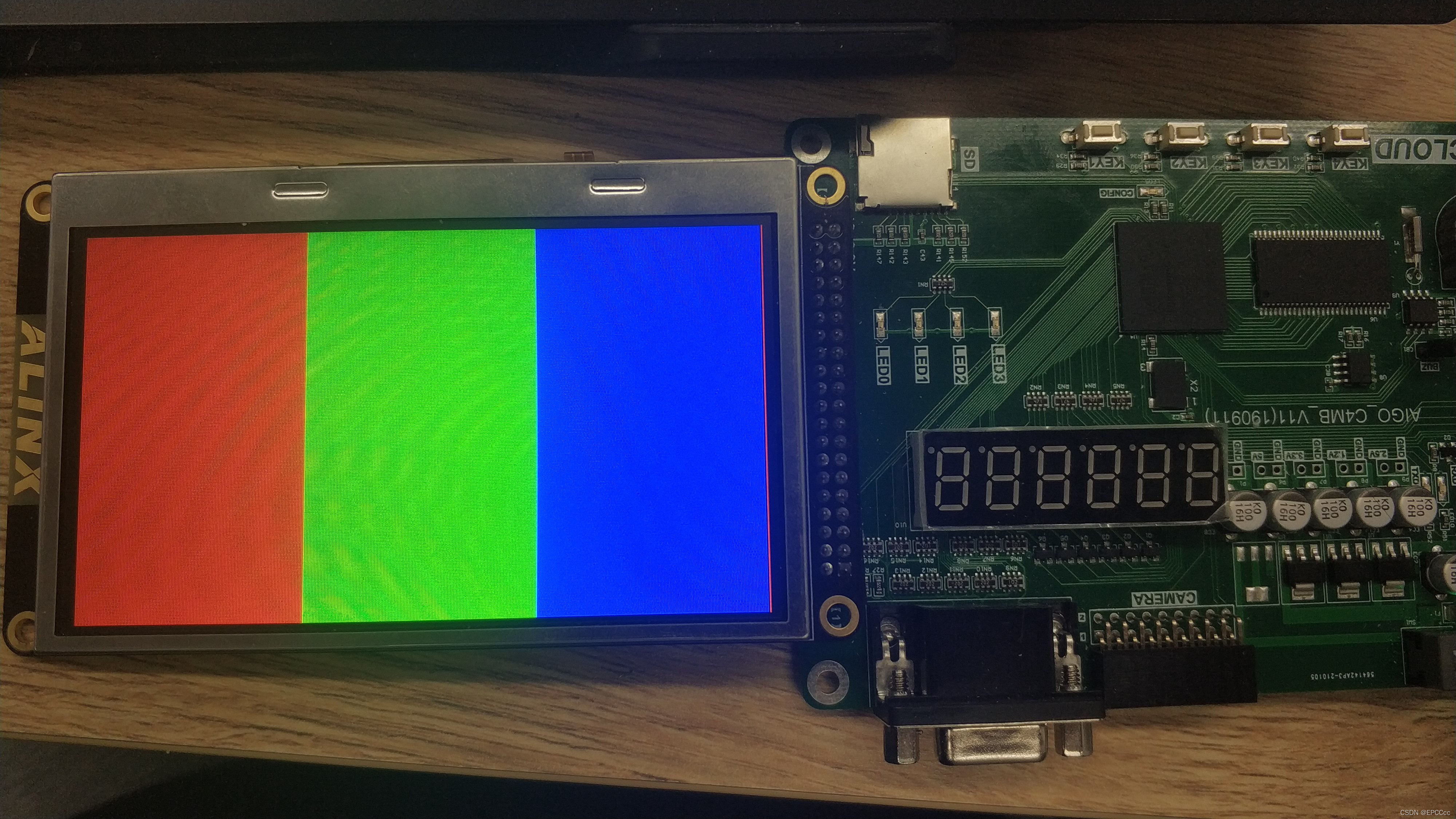
parameter RED = 24'b11111111_00000000_00000000,
GREEN = 24'b00000000_11111111_00000000,
BLUE = 24'b00000000_00000000_11111111,
BLACK = 24'b00000000_00000000_00000000;
// rgb数据寄存
reg [23:0] rgb_data_r;
always @(posedge clk or negedge rst_n)begin
if(!rst_n)begin
rgb_data_r <= BLACK;
end
else if((pixel_x >= 0) && (pixel_x < H_DISPLAY/3))begin
rgb_data_r <= RED;
end
else if((pixel_x >= H_DISPLAY/3) && (pixel_x < H_DISPLAY/3*2))begin
rgb_data_r <= GREEN;
end
else begin
rgb_data_r <= BLUE;
end
end
assign rgb_data = rgb_data_r;
endmodule
3.top.v
module top(
    input				clk		,
    input				rst_n	,
    output  [7:0]       lcd_r   ,
    output  [7:0]       lcd_g   ,
    output  [7:0]       lcd_b   ,
    output              lcd_vsync,
    output              lcd_hsync,
    output              lcd_dclk,
    output              lcd_disp,
    output              lcd_de
);

wire                clk_25m;
wire    [10:0]      pixel_x;
wire    [9:0]       pixel_y;
wire    [23:0]      rgb_data;


pll	pll_inst (
	.areset ( ~rst_n ),
	.inclk0 ( clk ),
	.c0     ( clk_25m ),
	.locked ( locked_sig )
	);


lcd_driver u_lcd_driver(
    /* input				*/.clk		(clk_25m ),
    /* input				*/.rst_n    (rst_n   ),
    /* input   [23:0]       */.rgb_data (rgb_data),
    /* output  [7:0]        */.lcd_r    (lcd_r   ),
    /* output  [7:0]        */.lcd_g    (lcd_g   ),
    /* output  [7:0]        */.lcd_b    (lcd_b   ),
    /* output               */.lcd_vsync(lcd_vsync),
    /* output               */.lcd_hsync(lcd_hsync),
    /* output               */.lcd_dclk (lcd_dclk),
    /* output               */.lcd_disp (lcd_disp),
    /* output               */.lcd_de   (lcd_de  ),
    /* output  [10:0]       */.pixel_x  (pixel_x ),
    /* output  [9:0]        */.pixel_y  (pixel_y )

);


lcd_show u_lcd_show(
    /* input                */.clk       (clk     ),
    /* input                */.rst_n     (rst_n   ),
    /* input   [10:0]       */.pixel_x   (pixel_x ),
    /* input   [9:0]        */.pixel_y   (pixel_y ),
    /* output  [23:0]       */.rgb_data  (rgb_data)
);
endmodule
四、仿真验证
这个就直接上板了
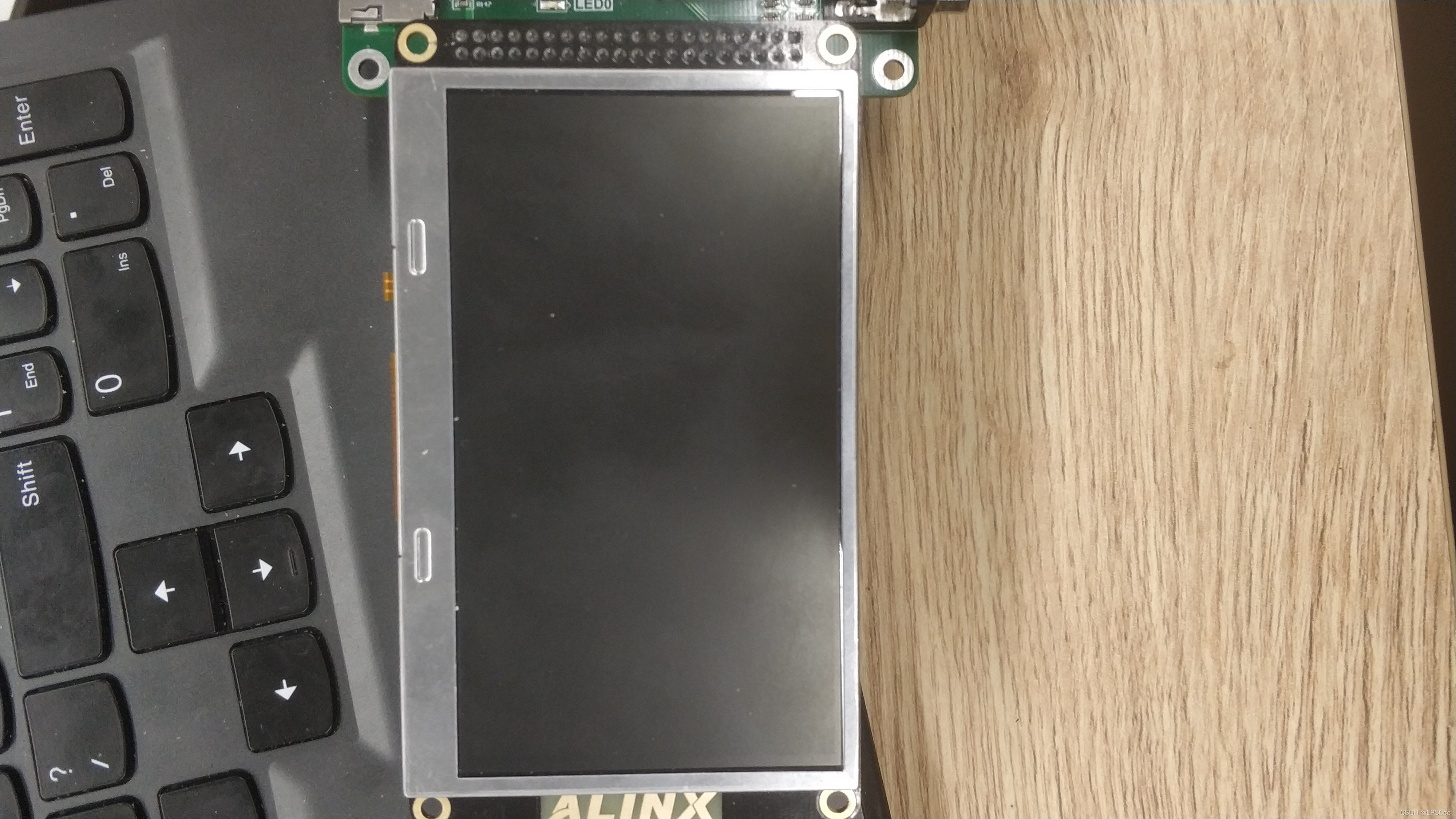
五、上板验证
六、总结
这个只是简单的看看那个手册的时序,然后写的驱动,其实lcd和vga一样的,只是lcd比vga多了几个信号,lcd是rgb888,vga是rgb565,数据转换一下,这个项目是为了摄像头而准备的,所有的学的到时候来个综合的。


 1840
1840


 被折叠的 条评论
为什么被折叠?
被折叠的 条评论
为什么被折叠?
 到【灌水乐园】发言


