


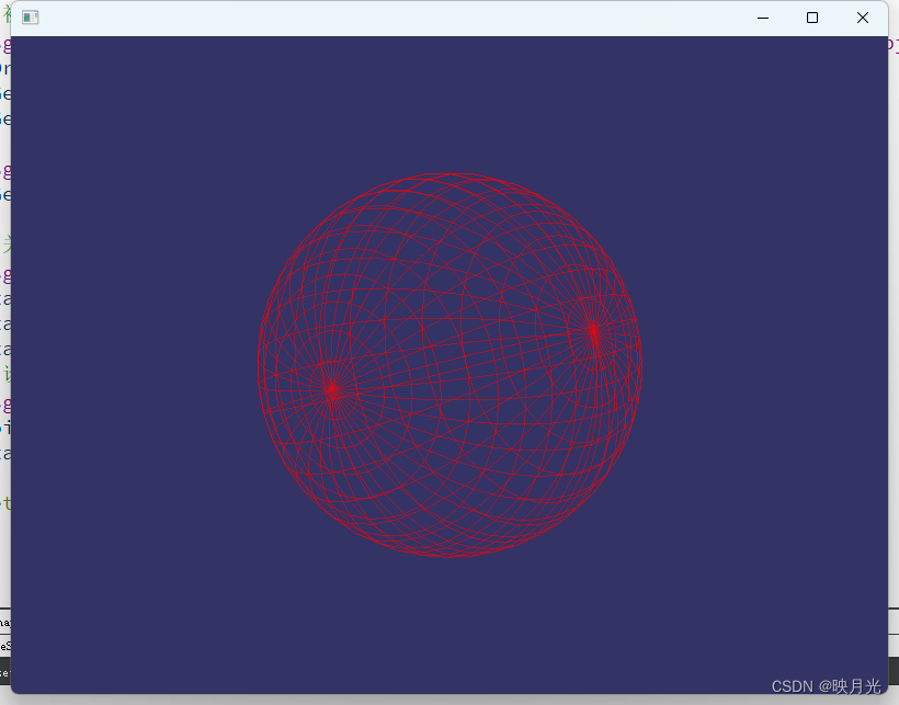
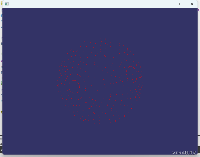
一、效果演示
按K键可以进行不同绘制方式的切换
二、逻辑分析
核心逻辑就是顶点数组的计算,设半径长为r,原点为O,球体表面上的任意点P(x, y, z)有x = r * sin(a) * cos(b);y = r * sin(a) * sin(b);z = r * cos(a);其中a为OP向量与z轴的夹角,b为OP向量在xoy平面上的投影与x轴的夹角,以夹角a和夹角b为自变量(-90° <= a <= 90°; 0° <= b <= 360°),循环求得球体表面的点为顶点,如下:
//生成球体的顶点,步长为10°(可以自由调整,但是最好是要能被整除,不然顶点不好对齐)
for(int angleXZ = -90; angleXZ <= 90; angleXZ+=10)
{
	//此处Z轴两级不需要遍历,就两个点,上下各一个
    if(angleXZ == -90 || angleXZ == 90)
    {
        float x = radius*cos(0* M_PI / 180.0)*sin((90-angleXZ)* M_PI / 180.0);
        float y = radius*sin(0* M_PI / 180.0)*sin((90-angleXZ)* M_PI / 180.0);
        float z = radius*cos((90-angleXZ)* M_PI / 180.0);
        pVertexArray->push_back(osg::Vec3f(x, y, z));
        pColorArray->push_back(osg::Vec4(1.0, 0.0, 0.0, 0.5));
    }
    else
    {
        for(int angleXY = 0; angleXY < 360; angleXY+=10)
        {
            float x = radius*cos(angleXY* M_PI / 180.0)*sin((90-angleXZ)* M_PI / 180.0);
            float y = radius*sin(angleXY* M_PI / 180.0)*sin((90-angleXZ)* M_PI / 180.0);
            float z = radius*cos((90-angleXZ)* M_PI / 180.0);
            pVertexArray->push_back(osg::Vec3f(x, y, z));
            pColorArray->push_back(osg::Vec4(1.0, 0.0, 0.0, 0.5));
        }
    }
}
上述将顶点计算出来后,需要按照一定的方式组织绘制,此处需要理解OSG的底层OPenGL的图元装配方式,然后根据其方式的对应特性进行组织顶点的绘制顺序,实在不行也可以亿点点的尝试,头铁,就硬搞,不服来干!如下:
//初始化顶点绘制顺序,其实这个顺序跟你选择的绘制方式有关osg::PrimitiveSet::LINE_STRIP_ADJACENCY,可以玩出各种花儿来
    osg::ref_ptr<osg::DrawElementsUInt>	pDrawEleUInt = new osg::DrawElementsUInt(osg::PrimitiveSet::LINE_STRIP_ADJACENCY);
    //底部
    for(int hI = 0; hI < 36; hI++)
    {
        pDrawEleUInt->push_back(0);
        pDrawEleUInt->push_back(1+hI);
    }
    for(int hI = 0; hI < 36; hI++)
    {
        pDrawEleUInt->push_back(1+hI);
    }
    //中间
    for(int vI = 0; vI < 16; vI++)
    {
        for(int hI = 0; hI < 36; hI++)
        {
            if(hI == 35)
            {
                pDrawEleUInt->push_back(vI*36+hI+1);
                pDrawEleUInt->push_back(vI*36+0+1);
            }
            else
            {
                pDrawEleUInt->push_back(vI*36+hI+1);
                pDrawEleUInt->push_back((vI+1)*36+hI+1);
                pDrawEleUInt->push_back((vI+1)*36+hI+2);
                pDrawEleUInt->push_back(vI*36+hI+2);
            }
        }
    }
    //顶部
    for(int hI = 0; hI < 36; hI++)
    {
        pDrawEleUInt->push_back(17*36+1);
        pDrawEleUInt->push_back(16*36+hI+1);
    }
    for(int hI = 0; hI < 36; hI++)
    {
        pDrawEleUInt->push_back(16*36+hI+1);
    }
    //初始化EBO缓冲,并将上述顶点绘制顺序关联
    osg::ref_ptr<osg::ElementBufferObject> pEboBuffer = new osg::ElementBufferObject;
    pDrawEleUInt->setElementBufferObject(pEboBuffer.get());
    pGeom->addPrimitiveSet(pDrawEleUInt.get());
    pGeom->setUseVertexBufferObjects(true);
三、整体代码实现
#include <iostream>

#include <osgDB/ReadFile>
#include <osgViewer/Viewer>
#include <osg/Node>
#include <osg/Geode>
#include <osg/Geometry>
#include <osg/Point>

using namespace std;

/**
 * @brief CreateSphereShape 创建球体形状的几何体
 * @param radius 半径
 * @return osg::ref_ptr<osg::Node> 球体形状节点
 */
osg::ref_ptr<osg::Node> CreateSphereShape(float radius);

//自定义访问器,更换绘制方式的
class CCustomVisitor : public osg::NodeVisitor
{
public:
    CCustomVisitor(){};

    void apply(osg::Geode& node) override
    {
        osg::Drawable* pDrawable = node.getDrawable(0);
        osg::PrimitiveSet* pPrimi = pDrawable->asGeometry()->getPrimitiveSet(0);
        osg::DrawElementsUInt* pDrawE = dynamic_cast<osg::DrawElementsUInt*>(pPrimi);
        if(pDrawE->getMode() == osg::PrimitiveSet::POINTS)
        {
            pDrawE->setMode(osg::PrimitiveSet::LINE_STRIP_ADJACENCY);
        }
        else
        {
            pDrawE->setMode(osg::PrimitiveSet::POINTS);
        }
    }
};

//自定义事件,处理几何模型的
class CCustomEvnet : public osgGA::GUIEventHandler
{
public:
    CCustomEvnet(osg::ref_ptr<osg::Node> pShape)
        : m_pShape(pShape){}

    bool handle(const osgGA::GUIEventAdapter& ea,osgGA::GUIActionAdapter& ee) override
    {
        (void)ee;

        if(ea.getEventType() == osgGA::GUIEventAdapter::KEYDOWN
                && ea.getKey() == osgGA::GUIEventAdapter::KEY_K)
        {
            CCustomVisitor visitor;
            m_pShape->accept(visitor);
        }
        return false;
    }

private:
    osg::ref_ptr<osg::Node> m_pShape;
};

int main()
{
    osgViewer::Viewer viewer;
    osg::ref_ptr<osg::Group> pRoot = new osg::Group;

    osg::ref_ptr<osg::Node> pShape = CreateSphereShape(50);


    pRoot->addChild(pShape);
    viewer.setSceneData(pRoot);
    viewer.setUpViewInWindow(100, 100, 800, 600);
    viewer.addEventHandler(new CCustomEvnet(pShape));
    viewer.run();
    return 0;
}

osg::ref_ptr<osg::Node> CreateSphereShape(float radius)
{
    //初始化相关对象
    osg::ref_ptr<osg::Geometry> pGeom = new osg::Geometry;
    osg::ref_ptr<osg::Vec3Array> pVertexArray = new osg::Vec3Array;
    pGeom->setVertexArray(pVertexArray.get());
    osg::ref_ptr<osg::Vec4Array> pColorArray = new osg::Vec4Array;
    pGeom->setColorArray(pColorArray.get());
    pGeom->setColorBinding(osg::Geometry::BIND_PER_VERTEX);

    //生成球体的顶点
    for(int angleXZ = -90; angleXZ <= 90; angleXZ+=10)
    {
        if(angleXZ == -90 || angleXZ == 90)
        {
            float x = radius*cos(0* M_PI / 180.0)*sin((90-angleXZ)* M_PI / 180.0);
            float y = radius*sin(0* M_PI / 180.0)*sin((90-angleXZ)* M_PI / 180.0);
            float z = radius*cos((90-angleXZ)* M_PI / 180.0);
            pVertexArray->push_back(osg::Vec3f(x, y, z));
            pColorArray->push_back(osg::Vec4(1.0, 0.0, 0.0, 0.5));
        }
        else
        {
            for(int angleXY = 0; angleXY < 360; angleXY+=10)
            {
                float x = radius*cos(angleXY* M_PI / 180.0)*sin((90-angleXZ)* M_PI / 180.0);
                float y = radius*sin(angleXY* M_PI / 180.0)*sin((90-angleXZ)* M_PI / 180.0);
                float z = radius*cos((90-angleXZ)* M_PI / 180.0);
                pVertexArray->push_back(osg::Vec3f(x, y, z));
                pColorArray->push_back(osg::Vec4(1.0, 0.0, 0.0, 0.5));
            }
        }
    }

    //初始化顶点绘制顺序,其实这个顺序跟你选择的绘制方式有关osg::PrimitiveSet::LINE_STRIP_ADJACENCY,可以玩出各种花儿来
    osg::ref_ptr<osg::DrawElementsUInt>	pDrawEleUInt = new osg::DrawElementsUInt(osg::PrimitiveSet::LINE_STRIP_ADJACENCY);
    //底部
    for(int hI = 0; hI < 36; hI++)
    {
        pDrawEleUInt->push_back(0);
        pDrawEleUInt->push_back(1+hI);
    }
    for(int hI = 0; hI < 36; hI++)
    {
        pDrawEleUInt->push_back(1+hI);
    }
    //中间
    for(int vI = 0; vI < 16; vI++)
    {
        for(int hI = 0; hI < 36; hI++)
        {
            if(hI == 35)
            {
                pDrawEleUInt->push_back(vI*36+hI+1);
                pDrawEleUInt->push_back(vI*36+0+1);
            }
            else
            {
                pDrawEleUInt->push_back(vI*36+hI+1);
                pDrawEleUInt->push_back((vI+1)*36+hI+1);
                pDrawEleUInt->push_back((vI+1)*36+hI+2);
                pDrawEleUInt->push_back(vI*36+hI+2);
            }
        }
    }
    //顶部
    for(int hI = 0; hI < 36; hI++)
    {
        pDrawEleUInt->push_back(17*36+1);
        pDrawEleUInt->push_back(16*36+hI+1);
    }
    for(int hI = 0; hI < 36; hI++)
    {
        pDrawEleUInt->push_back(16*36+hI+1);
    }
    //初始化EBO缓冲,并将上述顶点绘制顺序关联
    osg::ref_ptr<osg::ElementBufferObject> pEboBuffer = new osg::ElementBufferObject;
    pDrawEleUInt->setElementBufferObject(pEboBuffer.get());
    pGeom->addPrimitiveSet(pDrawEleUInt.get());
    pGeom->setUseVertexBufferObjects(true);

    osg::ref_ptr<osg::Geode> pGeode = new osg::Geode;
    pGeode->addDrawable(pGeom);

    //关闭光照,每个面看起来都一样
    osg::StateSet* stateSet = pGeode->getOrCreateStateSet();
    stateSet->setMode(GL_LIGHTING, osg::StateAttribute::OFF);
    stateSet->setMode(GL_DEPTH_TEST, osg::StateAttribute::ON);
    stateSet->setMode(GL_BLEND, osg::StateAttribute::ON);
    //设置点的大小
    osg::Point* pointSize = new osg::Point;
    pointSize->setSize(2.0);
    stateSet->setAttribute(pointSize);

    return  pGeode.get();
}


 853
853

 被折叠的 条评论
为什么被折叠?
被折叠的 条评论
为什么被折叠?
 到【灌水乐园】发言


