


4.Verification: Reading Simulation
4.1 Finding bugs in code
4.1.1 Mux
问题陈述:
这个8位的2对1多路复用器不起作用了。请修复错误。

输出的位宽没有正确一个为八位,且表达式也没有正确。
module top_module (
    input sel,
    input [7:0] a,
    input [7:0] b,
    output [7:0]out  );

    assign out = sel?a:b;

endmodule
4.1.2 NAND
问题陈述:
这个三输入的与非门不起作用。请修复错误。
你必须使用提供五输入的与门:
module andgate ( output out, input a, input b, input c, input d, input e );

位置没有一一对应,只与没有非。
module top_module (input a, input b, input c, output out);//
	wire temp_out;
    andgate inst1 (.out(temp_out),.a(a),.b(b),.c(c) ,.d(1'b1),.e(1'b1));
    assign out=~temp_out;

endmodule
4.1.3 Mux
问题陈述:
这个4选1多路复用器不起作用了。请修复错误
为你提供了一个无错误的2对1 多路复用器:
module mux2 (
input sel,
input [7:0] a,
input [7:0] b,
output [7:0] out
);

wire的位宽应该为8
module top_module (
    input [1:0] sel,
    input [7:0] a,
    input [7:0] b,
    input [7:0] c,
    input [7:0] d,
    output [7:0] out  ); //

    wire[7:0] u0, u1;
    mux2 mux0 ( sel[0],    a,    b, u0 );
    mux2 mux1 ( sel[0],    c,    d, u1 );
    mux2 mux2 ( sel[1], u0, u1,  out );

endmodule
4.1.4 Add/sub
问题陈述:
以下带有零标志的加法器不起作用了。请修复错误。

if的判断式不对,应该为out==8’b0.
module top_module (
    input do_sub,
    input [7:0] a,
    input [7:0] b,
    output reg [7:0] out,
    output reg result_is_zero
);//

    always @(*) begin
        case (do_sub)
          0: out = a+b;
          1: out = a-b;
        endcase

        if (out==8'b0)
            result_is_zero = 1;
        else
            result_is_zero = 0;
    end

endmodule
4.1.5 Case statement
问题陈述:
该组合电路一个识别0到9的8位键盘扫描吗。它一个指示10种情况的一种是否被识别(有效),如果是,则检测到哪个键。请修复错误。

module top_module (
    input [7:0] code,
    output reg [3:0] out,
    output reg valid );//

    always @(*) begin
        case (code)
            8'h45: out = 4'd0;
            8'h16: out = 4'd1;
            8'h1e: out = 4'd2;
            8'h26: out = 4'd3;
            8'h25: out = 4'd4;
            8'h2e: out = 4'd5;
            8'h36: out = 4'd6;
            8'h3d: out = 4'd7;
            8'h3e: out = 4'd8;
            8'h46: out = 4'd9;
            default: out=4'd0;
        endcase
        if((out==0)&(code!=8'h45))
           valid=1'b0;
        else
            valid=1'b1;
           end

endmodule
4.2 Build a circuit from a simulation waveform
4.2.1 Combination citrcuit1
问题陈述:
这是一个组合电路。阅读仿真波形以确定电路的作用,然后实现它。

信号a和信号b同为高电平时,输出高电平。
Verilog代码:
module top_module (
    input a,
    input b,
    output q );//

    assign q = a&b;

endmodule
4.2.2 Combination citrcuit 2
问题陈述:
这是一个组合电路。阅读仿真波形以确定电路的作用,然后实现它。

Verilog代码:
module top_module (
    input a,
    input b,
    input c,
    input d,
    output q );//

    assign q = (~a&~b&~c&~d)|(~a&~b&c&d)|(~a&b&~c&d)|(~a&b&c&~d)|(a&b&~c&~d)||(a&b&c&d)||(a&~b&~c&d)||(a&~b&c&~d);

endmodule
4.2.3 Combination citrcuit 3
问题陈述:
这是一个组合电路。阅读仿真波形以确定电路的作用,然后实现它。

Verillog代码:
module top_module (
    input a,
    input b,
    input c,
    input d,
    output q );//

    assign q = (a&d)|(b&d)|(b&c)|(a&c);

endmodule
4.2.4 Combination citrcuit 4
问题陈述:
这是一个组合电路。阅读仿真波形以确定电路的作用,然后实现它。

Verilog代码:
module top_module (
    input a,
    input b,
    input c,
    input d,
    output q );//

    assign q = b|c;

endmodule
4.2.5 Combination citrcuit 5
问题陈述:
这是一个组合电路。阅读仿真波形以确定电路的作用,然后实现它。

Verilog代码:
module top_module (
    input [3:0] a,
    input [3:0] b,
    input [3:0] c,
    input [3:0] d,
    input [3:0] e,
    output [3:0] q );
    always@(*)
        begin
            case(c)
                4'b0000:q=b;
                4'b0001:q=e;
                4'b0010:q=a;
                4'b0011:q=d;
                default: q=4'b1111;
            endcase
        end
endmodule
4.2.6 Combination citrcuit 6
问题陈述:
这是一个组合电路。阅读仿真波形以确定电路的作用,然后实现它。

Verilog代码:
module top_module (
    input [2:0] a,
    output [15:0] q );
    always@(*)
        begin
            case(a)
                3'b000:q=16'h1232;
                3'b001:q=16'haee0;
                3'b010:q=16'h27d4;
                3'b011:q=16'h5a0e;
                3'b100:q=16'h2066;
                3'b101:q=16'h64ce;
                3'b110:q=16'hc526;
                3'b111:q=16'h2f19;
            endcase
        end
endmodule
4.2.7 Sequentional circuit 7
问题陈述:
这是一个时序电路。阅读仿真波形以确定电路的作用,然后实现它。
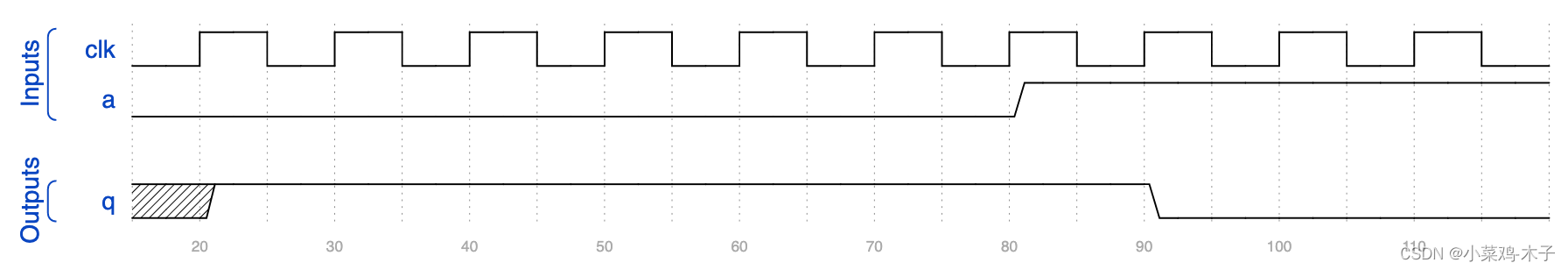
Verilog代码:
module top_module (
    input clk,
    input a,
    output q );
    always@(posedge clk)
        begin
            q<=~a;
        end
endmodule
4.2.8 Sequentional circuit 8
问题陈述:
这是一个时序电路。阅读仿真波形以确定电路的作用,然后实现它。

Verilog代码:
module top_module (
    input clock,
    input a,
    output p,
    output q );
	assign p=clock?a:p;
    always@(negedge clock)
        begin
            q<=p;
        end
endmodule
4.2.9 Sequentional circuit 9
问题陈述:
这是一个时序电路。阅读仿真波形以确定电路的作用,然后实现它。

Verilog代码:
module top_module (
    input clk,
    input a,
    output [3:0] q );
    always@(posedge clk)
        begin
            if(a)
                q<=4'd4;
            else if(q>=4'd6)
                q<=4'd0;
            else
                q<=q+1'b1;
        end
endmodule
4.2.10 Sequentional circuit 10、
问题陈述:
这是一个时序电路。该电路有由组合逻辑和一位存储器(即一个触发器)组成。触发器的输出可以通过输出状态观察到。
阅读仿真波形确定电路的作用,然后实现它。Verilog代码:
module top_module (
    input clk,
    input a,
    input b,
    output q,
    output state  );
	assign q=a^b^state;
    always@(posedge clk)
        begin
            if(a&b)
                state<=1'b1;
            else if(~a&~b)
                state<=1'b0;
            else
                state<=state;
        end
endmodule


 2114
2114


 被折叠的 条评论
为什么被折叠?
被折叠的 条评论
为什么被折叠?
 到【灌水乐园】发言


