


一、创建编译功能包
切换到catkin_ws/src目录下,如下:
cd catkin_ws/src
catkin_create_pkg mbot_sim_gazebo_navigation urdf xacro
返回到catkin_ws目录下,编译该功能包,如下:
cd ..
catkin_make mbot_sim_gazebo_navigation在该功能包下创建include、src、launch、urdf、world、map、script文件夹,在urdf文件下创建urdf文件夹和xacro文件夹。
cd src/mbot_sim_gazebo_navigation
mkdir include
mkdir src
mkdir launch
mkdir urdf
mkdir world
mkdir map
mkdir script
cd urdf
mkdir urdf
mkdir xacro
二、xacro文件
1、创建robot_base.xacro文件
切换到xacro文件下,创建robot_base.xacro文件,文件内容如下:
<?xml version="1.0"?>
<robot name="mbot" xmlns:xacro="http://www.ros.org/wiki/xacro">

    <!-- PROPERTY LIST -->
    <xacro:property name="M_PI" value="3.1415926"/>
    <xacro:property name="base_mass"   value="20" />
    <xacro:property name="base_radius" value="0.20"/>
    <xacro:property name="base_length" value="0.16"/>

    <xacro:property name="wheel_mass"   value="2" />
    <xacro:property name="wheel_radius" value="0.06"/>
    <xacro:property name="wheel_length" value="0.025"/>
    <xacro:property name="wheel_joint_y" value="0.19"/>
    <xacro:property name="wheel_joint_z" value="0.05"/>

    <xacro:property name="caster_mass"    value="0.5" />
    <xacro:property name="caster_radius"  value="0.015"/> <!-- wheel_radius - ( base_length/2 - wheel_joint_z) -->
    <xacro:property name="caster_joint_x" value="0.18"/>

    <!-- Defining the colors used in this robot -->
    <material name="yellow">
        <color rgba="1 0.4 0 1"/>
    </material>
    <material name="black">
        <color rgba="0 0 0 0.95"/>
    </material>
    <material name="gray">
        <color rgba="0.75 0.75 0.75 1"/>
    </material>

    <!-- Macro for inertia matrix -->
    <xacro:macro name="sphere_inertial_matrix" params="m r">
        <inertial>
            <mass value="${m}" />
            <inertia ixx="${2*m*r*r/5}" ixy="0" ixz="0"
                iyy="${2*m*r*r/5}" iyz="0"
                izz="${2*m*r*r/5}" />
        </inertial>
    </xacro:macro>

    <xacro:macro name="cylinder_inertial_matrix" params="m r h">
        <inertial>
            <mass value="${m}" />
            <inertia ixx="${m*(3*r*r+h*h)/12}" ixy = "0" ixz = "0"
                iyy="${m*(3*r*r+h*h)/12}" iyz = "0"
                izz="${m*r*r/2}" />
        </inertial>
    </xacro:macro>

    <!-- Macro for robot wheel -->
    <xacro:macro name="wheel" params="prefix reflect">
        <joint name="${prefix}_wheel_joint" type="continuous">
            <origin xyz="0 ${reflect*wheel_joint_y} ${-wheel_joint_z}" rpy="0 0 0"/>
            <parent link="base_link"/>
            <child link="${prefix}_wheel_link"/>
            <axis xyz="0 1 0"/>
        </joint>

        <link name="${prefix}_wheel_link">
            <visual>
                <origin xyz="0 0 0" rpy="${M_PI/2} 0 0" />
                <geometry>
                    <cylinder radius="${wheel_radius}" length = "${wheel_length}"/>
                </geometry>
                <material name="gray" />
            </visual>
            <collision>
                <origin xyz="0 0 0" rpy="${M_PI/2} 0 0" />
                <geometry>
                    <cylinder radius="${wheel_radius}" length = "${wheel_length}"/>
                </geometry>
            </collision>
            <cylinder_inertial_matrix  m="${wheel_mass}" r="${wheel_radius}" h="${wheel_length}" />
        </link>

        <gazebo reference="${prefix}_wheel_link">
            <material>Gazebo/Gray</material>
        </gazebo>

        <!-- Transmission is important to link the joints and the controller-->
        <transmission name="${prefix}_wheel_joint_trans">
            <type>transmission_interface/SimpleTransmission</type>
            <joint name="${prefix}_wheel_joint" >
                <hardwareInterface>hardware_interface/VelocityJointInterface</hardwareInterface>
            </joint>
            <actuator name="${prefix}_wheel_joint_motor">
                <hardwareInterface>hardware_interface/VelocityJointInterface</hardwareInterface>
                <mechanicalReduction>1</mechanicalReduction>
            </actuator>
        </transmission>
    </xacro:macro>

    <!-- Macro for robot caster -->
    <xacro:macro name="caster" params="prefix reflect">
        <joint name="${prefix}_caster_joint" type="continuous">
            <origin xyz="${reflect*caster_joint_x} 0 ${-(base_length/2 + caster_radius)}" rpy="0 0 0"/>
            <parent link="base_link"/>
            <child link="${prefix}_caster_link"/>
            <axis xyz="0 1 0"/>
        </joint>

        <link name="${prefix}_caster_link">
            <visual>
                <origin xyz="0 0 0" rpy="0 0 0"/>
                <geometry>
                    <sphere radius="${caster_radius}" />
                </geometry>
                <material name="black" />
            </visual>
            <collision>
                <origin xyz="0 0 0" rpy="0 0 0"/>
                <geometry>
                    <sphere radius="${caster_radius}" />
                </geometry>
            </collision>
            <sphere_inertial_matrix  m="${caster_mass}" r="${caster_radius}" />
        </link>

        <gazebo reference="${prefix}_caster_link">
            <material>Gazebo/Black</material>
        </gazebo>
    </xacro:macro>

    <xacro:macro name="mbot_base_gazebo">
        <link name="base_footprint">
            <visual>
                <origin xyz="0 0 0" rpy="0 0 0" />
                <geometry>
                    <box size="0.001 0.001 0.001" />
                </geometry>
            </visual>
        </link>
        <gazebo reference="base_footprint">
            <turnGravityOff>false</turnGravityOff>
        </gazebo>

        <joint name="base_footprint_joint" type="fixed">
            <origin xyz="0 0 ${base_length/2 + caster_radius*2}" rpy="0 0 0" />
            <parent link="base_footprint"/>
            <child link="base_link" />
        </joint>

        <link name="base_link">
            <visual>
                <origin xyz=" 0 0 0" rpy="0 0 0" />
                <geometry>
                    <cylinder length="${base_length}" radius="${base_radius}"/>
                </geometry>
                <material name="yellow" />
            </visual>
            <collision>
                <origin xyz=" 0 0 0" rpy="0 0 0" />
                <geometry>
                    <cylinder length="${base_length}" radius="${base_radius}"/>
                </geometry>
            </collision>
            <cylinder_inertial_matrix  m="${base_mass}" r="${base_radius}" h="${base_length}" />
        </link>

        <gazebo reference="base_link">
            <material>Gazebo/Blue</material>
        </gazebo>

        <wheel prefix="left"  reflect="-1"/>
        <wheel prefix="right" reflect="1"/>

        <caster prefix="front" reflect="-1"/>
        <caster prefix="back"  reflect="1"/>

        <!-- controller -->
        <gazebo>
            <plugin name="differential_drive_controller"
                    filename="libgazebo_ros_diff_drive.so">
                <rosDebugLevel>Debug</rosDebugLevel>
                <publishWheelTF>true</publishWheelTF>
                <robotNamespace>/</robotNamespace>
                <publishTf>1</publishTf>
                <publishWheelJointState>true</publishWheelJointState>
                <alwaysOn>true</alwaysOn>
                <updateRate>100.0</updateRate>
                <legacyMode>true</legacyMode>
                <leftJoint>right_wheel_joint</leftJoint>
                <rightJoint>left_wheel_joint</rightJoint>
                <wheelSeparation>${wheel_joint_y*2}</wheelSeparation>
                <wheelDiameter>${2*wheel_radius}</wheelDiameter>
                <broadcastTF>1</broadcastTF>
                <wheelTorque>30</wheelTorque>
                <wheelAcceleration>1.8</wheelAcceleration>
                <commandTopic>cmd_vel</commandTopic>
                <odometryFrame>odom</odometryFrame>
                <odometryTopic>odom</odometryTopic>
                <robotBaseFrame>base_footprint</robotBaseFrame>
		<odometrySource>world</odometrySource>
		<publishOdomTF>1</publishOdomTF>
            </plugin>
        </gazebo>
    </xacro:macro>
</robot>
2、创建robot_camera.xacro文件
在xacro文件下,创建robot_camera.xacro文件,文件内容如下:
<?xml version="1.0"?>

<robot xmlns:xacro="http://www.ros.org/wiki/xacro" name="camera">


    <xacro:macro name="usb_camera" params="prefix:=camera">

        <!-- Create laser reference frame -->

        <link name="${prefix}_link">

            <inertial>

                <mass value="0.1" />

                <origin xyz="0 0 0" />

                <inertia ixx="0.01" ixy="0.0" ixz="0.0"

                         iyy="0.01" iyz="0.0"

                         izz="0.01" />

            </inertial>


            <visual>

                <origin xyz=" 0 0 0 " rpy="0 0 0" />

                <geometry>

                    <box size="0.01 0.04 0.04" />

                </geometry>

                <material name="black"/>

            </visual>


            <collision>

                <origin xyz="0.0 0.0 0.0" rpy="0 0 0" />

                <geometry>

                    <box size="0.01 0.04 0.04" />

                </geometry>

            </collision>

        </link>

        <gazebo reference="${prefix}_link">

            <material>Gazebo/Black</material>

        </gazebo>


        <gazebo reference="${prefix}_link">

            <sensor type="camera" name="camera_node">

                <update_rate>30.0</update_rate>

                <camera name="head">

                    <horizontal_fov>1.3962634</horizontal_fov>

                    <image>

                        <width>1280</width>

                        <height>720</height>

                        <format>R8G8B8</format>

                    </image>

                    <clip>

                        <near>0.02</near>

                        <far>300</far>

                    </clip>

                    <noise>

                        <type>gaussian</type>

                        <mean>0.0</mean>

                        <stddev>0.007</stddev>

                    </noise>

                </camera>

                <plugin name="gazebo_camera" filename="libgazebo_ros_camera.so">

                    <alwaysOn>true</alwaysOn>

                    <updateRate>0.0</updateRate>

                    <cameraName>/camera</cameraName>

                    <imageTopicName>image_raw</imageTopicName>

                    <cameraInfoTopicName>camera_info</cameraInfoTopicName>

                    <frameName>camera_link</frameName>

                    <hackBaseline>0.07</hackBaseline>

                    <distortionK1>0.0</distortionK1>

                    <distortionK2>0.0</distortionK2>

                    <distortionK3>0.0</distortionK3>

                    <distortionT1>0.0</distortionT1>

                    <distortionT2>0.0</distortionT2>

                </plugin>

            </sensor>

        </gazebo>


    </xacro:macro>

</robot>
3、创建robot_lidar.xacro文件
在xacro文件下,创建robot_lidar.xacro文件,文件内容如下:
<?xml version="1.0"?>
<robot xmlns:xacro="http://www.ros.org/wiki/xacro" name="lidar">
	<xacro:macro name="hokuyo_lidar" params="prefix:=lidar">
			<link name="hokuyo_link">
	    		<collision>
	      			<origin xyz="0 0 0" rpy="0 0 0"/>
	      			<geometry>
						<box size="0.1 0.1 0.1"/>
	     			</geometry>
	    		</collision>
	    		<visual>
	      			<origin xyz="0 0 0" rpy="0 0 0"/>
	      			<geometry>
	        			<mesh filename="package://mbot_sim_gazebo_navigation/meshes/hokuyo.dae"/>
	      			</geometry>
	    		</visual>
	    		<inertial>
	      			<mass value="1e-5" />
	      			<origin xyz="0 0 0" rpy="0 0 0"/>
	      			<inertia ixx="1e-6" ixy="0" ixz="0" iyy="1e-6" iyz="0" izz="1e-6" />
	    		</inertial>
	  		</link>
			<gazebo reference="hokuyo_link">
			    <sensor type="ray" name="head_hokuyo_sensor">
			      <pose>0 0 0 0 0 0</pose>
			      <visualize>false</visualize>
			      <update_rate>40</update_rate>
			      <ray>
			        <scan>
			          <horizontal>
			            <samples>720</samples>
			            <resolution>1</resolution>
			            <min_angle>-1.570796</min_angle>
			            <max_angle>1.570796</max_angle>
			          </horizontal>
			        </scan>
			        <range>
			          <min>0.10</min>
			          <max>30.0</max>
			          <resolution>0.01</resolution>
			        </range>
			        <noise>
			          <type>gaussian</type>
			          <mean>0.0</mean>
			          <stddev>0.01</stddev>
			        </noise>
			      </ray>
			      <plugin name="gazebo_ros_head_hokuyo_controller" filename="libgazebo_ros_laser.so">
			        <topicName>/scan</topicName>
			        <frameName>hokuyo_link</frameName>
			      </plugin>
			    </sensor>
			  </gazebo>
	</xacro:macro>
</robot>4、创建robot.xacro文件
在xacro文件下,创建robot.xacro文件,文件内容如下:
<?xml version="1.0"?>

<robot name="arm" xmlns:xacro="http://www.ros.org/wiki/xacro">


    <xacro:include filename="$(find mbot_sim_gazebo_navigation)/urdf/xacro/robot_base.xacro" />

    <xacro:include filename="$(find mbot_sim_gazebo_navigation)/urdf/xacro/robot_camera.xacro" />

    <xacro:include filename="$(find mbot_sim_gazebo_navigation)/urdf/xacro/robot_lidar.xacro" />


    <xacro:property name="camera_offset_x" value="0.17" />

    <xacro:property name="camera_offset_y" value="0" />

    <xacro:property name="camera_offset_z" value="0.10" />

    <xacro:property name="lidar_offset_x" value="-0.17" />

    <xacro:property name="lidar_offset_y" value="0" />

    <xacro:property name="lidar_offset_z" value="0.10" />


    <xacro:mbot_base_gazebo/>


    <!-- Camera -->

    <joint name="camera_joint" type="fixed">

        <origin xyz="${camera_offset_x} ${camera_offset_y} ${camera_offset_z}" rpy="0 0 0" />

        <parent link="base_link"/>

        <child link="camera_link"/>

    </joint>


    <xacro:usb_camera prefix="camera"/>


    <joint name="lidar_joint" type="fixed">

        <origin xyz="${lidar_offset_x} ${lidar_offset_y} ${lidar_offset_z}" rpy="0 0 0" />

        <parent link="base_link"/>

        <child link="hokuyo_link"/>

    </joint>

    <xacro:hokuyo_lidar prefix="lidar"/>


</robot>
接下来需要将.gazebo/models/hokuyo/目录中的meshes文件夹整体复制到我们的功能包mbot_sim_gazebo下面。将桌面上准备的room.world文件,放在功能包下的world文件夹里面。将上一个功能包扫完的那两个文件复制到此功能包里面的map文件里。将opt/ros/melodic/lib/teleop_twist_keyboard文件夹下的teleop_twist_keyboard.py文件放入目前功能包里面的script文件夹
三、代价地图yaml配置
机器人使用两种导航算法在地图中移动:全局导航和局部导航。
全局导航:用于建立到地图上最终目标或一个远距离目标的路径。
局部导航:用于建立到近距离目标和为了临时躲避障碍物的路径。
这些导航算法通过使用代价地图来处理地图中的各种信息。代价地图的参数用于配置算法计算行为。
全局代价地图用于全局导航,局部代价地图用于局部导航。它们也有最基本的通用参数,这些参数会保存在共享的文件中。
1、创建costmap_common_params.yaml文件
切换到launch文件下,创建costmap_common_params.yaml文件,文件内容如下:
obstacle_range: 2.5
raytrace_range: 3.0
robot_radius: 0.2
inflation_radius: 0.6
cost_scaling_factor: 10.0
observation_sources: scan
scan: {sensor_frame: lidar_link, data_type: LaserScan, topic: /scan, marking: true, clearing: true}
解释costmap_common_params.yaml文件
obstacle_range:表示传感器的最大探测距离,意味着机器人只会更新2.5米内的障碍物信息。
raytrace_range:确定用于清除指定范围外的空间,意味着机器人将尝试清除3米外的障碍物。
footprint:设置机器人的占用面积或机器人的半径是圆形。假设机器人的中心处于(0.0,0.0),并且支持顺时针和逆时针规格。如果是圆形机器人,直接使用robot_radius参数。
inflation_radius:设置膨胀半径,意味着机器人针对相同的障碍物获取的所有路径都保持距离障碍物0.1米或更远。如果你的机器人不能很好地通过窄门或其它狭窄的地方,则稍微减小这个值。相反地,如果机器人不断地撞到东西,则尝试增大这个值。
cost_scaling_factor:修改机器人绕过障碍物的行为。
observation_sources:设定导航功能包所使用的传感器列表,传感器之间用空格分隔。这是我们使用的是自定义的激光雷达。
scan:设置上面传感器的信息。sensor_frame表示传感器坐标名;data_type表示话题使用的消息类型;topic_name表示传感器发布数据的话题名称;marking和clearing参数确定传感器是否向代价地图添加障碍物信息或从代价地图中清除障碍物信息,或者同时都做。
2、创建global_costmap_params.yaml文件
切换到launch文件下,创建global_costmap_params.yaml文件,文件内容如下:
global_costmap:
  global_frame: map
  robot_base_frame: base_link
  update_frequency: 1.0
  static_map: true
解释global_costmap_params.yaml文件
global_frame:定义代价地图运行的坐标系。
robot_base_frame:定义代价地图应该为机器人的基座的坐标系。
update_frequency:设置地图更新的频率。通常设定一个相对较小,在1.0到5.0之间的值。
static_map:是否由map_server提供的地图服务来进行代价地图的初始化。
3、创建local_costmap_params.yaml文件
切换到launch文件下,创建local_costmap_params.yaml文件,文件内容如下:
local_costmap:
  global_frame: map
  robot_base_frame: base_footprint
  update_frequency: 5.0
  publish_frequency: 1.0
  rolling_window: true
  width: 5.0
  height: 5.0
  resolution: 0.05
  tranform_tolerance: 1.0
  planner_frequency: 1.0
  planner_patiente: 5.0
解释local_costmap_params.yaml文件
publish_frequency:设置代价地图发布可视化信息的速率。
rolling_window:设置是否保持机器人运动过程中,代价地图始终以机器人为中心,为true则在中心。
width:设置本地代价地图的宽度。
height:设置本地代价地图的高度。
resolution:设置本地代价地图的分辨率(米/单元格)。这个网格的分辨率与静态地图的分辨率不同,但大多数时候我们倾向设置为相同值。
tranform_tolerance:设置转换的最大延迟(秒)。
planner_frequency:设置规划循环的频率。
planner_patiente:设置在执行空间清理操作前,规划器寻找一条有效路径的等待时间(秒)。
4、创建base_local_planner_params.yaml文件
切换到launch文件下,创建base_local_planner_params.yaml文件,文件内容如下:
TrajectoryPlannerROS:
  controller_frequency: 3.0
  max_vel_x: 0.3
  min_vel_x: 0.05
  max_rotational_vel: 0.5
  min_in_place_rotational_vel: 0.01
  min_in_place_vel_theta: 0.5
  escape_vel: -0.1
  max_vel_theta: 1.0
  min_vel_theta: -1.0
  acc_lim_theta: 3.2
  acc_lim_x: 2.5
  acc_lim_y: 2.5
  yaw_goal_tolerance: 0.1
  xy_goal_tolerance: 0.1
  path_distance_bias: 0.8
  goal_distance_bias: 0.4
  holonomic_robot: false
  meter_scoring: true
解释base_local_planner_params.yaml文件
第一部分,定义机器人的速度限制。
第二部分,定义机器人的加速度限制。
holonomic_robot:全向移动机器人,机器人能够前后左右移动,能从任意位置向指定位置移动,则该值为true;差分移动机器人,为非全向移动机器人,该值为false
四、创建导航包的启动文件
robot_gazebo_navigation.launch启动文件,内容如下:
<launch>
    <arg name="paused" default="true"/>
    <arg name="use_sim_time" default="true"/>
    <arg name="gui" default="true"/>
    <arg name="headless" default="false"/>
    <arg name="debug" default="false"/>
    <remap from="robot/laser/scan" to="/scan"/>

    <include file="$(find gazebo_ros)/launch/empty_world.launch">
   	<arg name="world_name" value="$(find mbot_sim_gazebo_navigation)/world/room.world"/>
    	<arg name="debug" value="$(arg debug)" />
    	<arg name="gui" value="$(arg gui)" />
    </include>

    <!--机器人参数设置-->
    <arg name="model" default="$(find mbot_sim_gazebo_navigation)/urdf/xacro/robot.xacro" />
    <param name="robot_description" command="$(find xacro)/xacro.py $(arg model)" />

      <!-- 在gazebo中加载机器人模型-->
    <node name="urdf_spawner" pkg="gazebo_ros" type="spawn_model" respawn="false" output="screen"
          args="-urdf -model robot -param robot_description -z 0.05"/>
    <node name="rviz" pkg="rviz" type="rviz" args="-d $(find mbot_sim_gazebo_navigation)/urdf/xacro/default.rviz"/>

    <!-- 运行joint_state_publisher节点,发布机器人的关节状态  -->
    <node name="joint_state_publisher" pkg="joint_state_publisher" type="joint_state_publisher" />

    <!-- 运行robot_state_publisher节点,发布tf  -->
    <node name="robot_state_publisher" pkg="robot_state_publisher" type="robot_state_publisher" />
</launch>
robot_gazebo_navigation_move.launch启动文件,内容如下:
<?xml version="1.0"?>
<launch>
<node name="map_server" pkg="map_server" type="map_server" args="$(find mbot_sim_gazebo_navigation)/map/myMapFile.yaml" output="screen"/>
<include file="$(find amcl)/examples/amcl_diff.launch">
<!-- 设置一个 baselink与 laser之间的静态坐标变换 -->
<node pkg="tf" type="static_transform_publisher" name="base_to_laser_broadcaster" args="0 0 0 0 0 0 /base_link /laser 100"/>
</include>
<node pkg="move_base" type="move_base" name="move_base" output="screen">
<param name="controller_frequency" value="10.0"/>
<param name="controller_patiente" value="15.0"/>
<rosparam file="$(find mbot_sim_gazebo_navigation)/launch/costmap_common_params.yaml" command="load" ns="global_costmap"/>
<rosparam file="$(find mbot_sim_gazebo_navigation)/launch/costmap_common_params.yaml" command="load" ns="local_costmap"/>
<rosparam file="$(find mbot_sim_gazebo_navigation)/launch/local_costmap_params.yaml" command="load"/>
<rosparam file="$(find mbot_sim_gazebo_navigation)/launch/global_costmap_params.yaml" command="load"/>
<rosparam file="$(find mbot_sim_gazebo_navigation)/launch/base_local_planner_params.yaml" command="load"/>
</node>
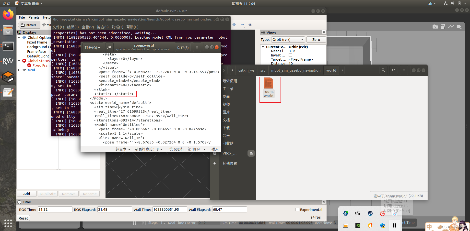
</launch>修改world文件
点击创建的room.world文件,将static旁边的数值修改为1
五、运行启动文件
首先运行robot_gazebo_navigation.launch,效果如下:
roslaunch mbot_sim_gazebo_navigation robot_gazebo_navigation.launch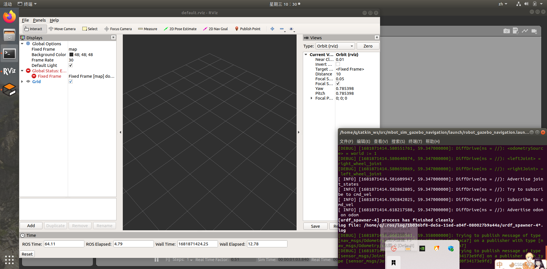
再运行robot_gazebo_navigation_move.launch,效果如下:
roslaunch mbot_sim_gazebo_navigation robot_gazebo_navigation_move.launch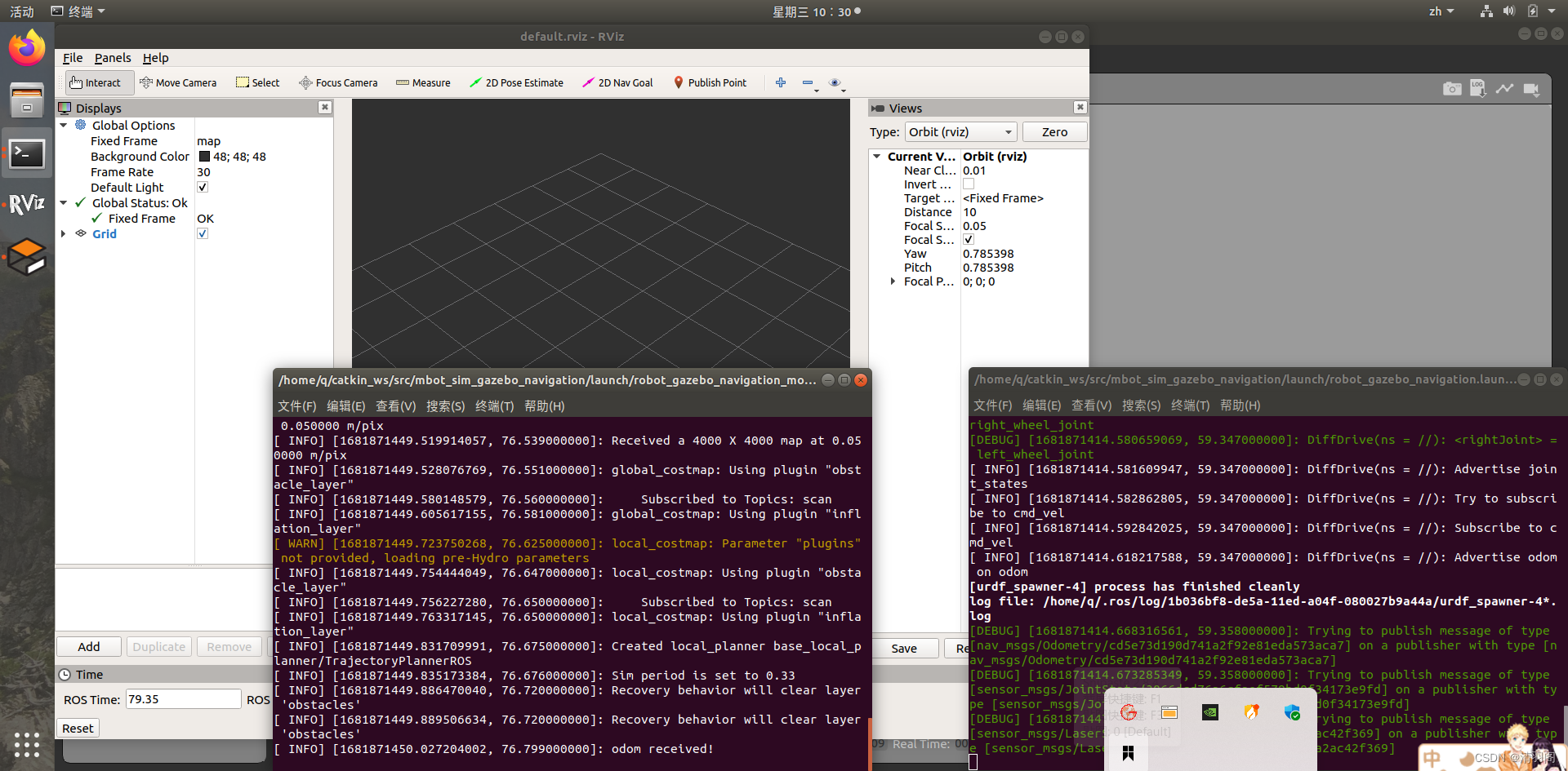
六、为导航功能包集设置rviz
1、添加RobotModel,可以看到我们使用的模型。
2、添加Polygon,本例中机器人占地空间有0.4米宽,0.4米高,该参数可以在costmap_common_params文件中配置。这个尺寸对于导航功能包集来说很重要, 因为只有配置正确才能保证机器人的运动安全。topic可以设置为/move_base/global_costmap/footprint
3、添加Global Costmap,为了实现避障,机器人的立足点应当永远不能与包含障碍物的单元格相交。机器人的中心位置不应在包含障碍物膨胀区的单元格内。topic为/move_base/global_costmap/costmap
4、添加Local Costmap,topic为/move_base/local_costmap/costmap
5、添加Global Plan,可以观察到全局路径规划中的部分路径,机器人在运动过程中还会发现障碍物,导航功能包为了避免碰撞就会在尽量保证全局规划的基础上重新计算路径。topic为/move_base/TrajectoryPlannerROS/global_plan
6、添加Local Plan,机器人执行由局部规划器生成的速度命令以及将会形成的运动轨迹,通过这些可以了解机器人是否在运动,并根据轨迹长度对机器人的运动速度进行估计。topic为/move_base/TrajectoryPlannerROS/local_plan
7、添加Planner Plan,可以观察到由全局规划器计算的完整路径。可以看到这些线条和全局规划中的线条很类似。 topic为/move_base/NavfnROS/plan
8、添加LaserScan,可以看到激光雷达扫描的障碍物。topic为scan
9、添加Pose,用一个红色的箭头表示,重新配置一个新的2D导航目标后才会出现。topic为/move_base/current_goal
10、添加Particle Cloud,点云的分布表示在定位系统中机器人位姿的不确定性。分散的点云代表较高的不确定性,聚集的点云代表较低的不确定性。topic为/particlecloud
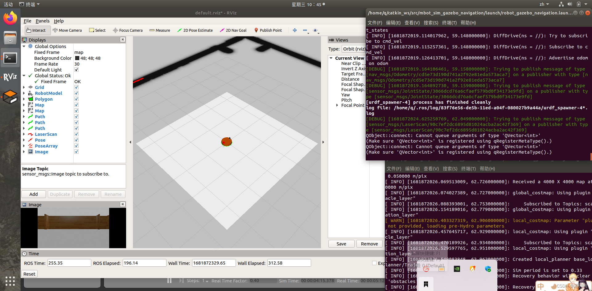
11、添加Image,可以观察到摄像头捕捉的图像。topic为/camera/image_raw
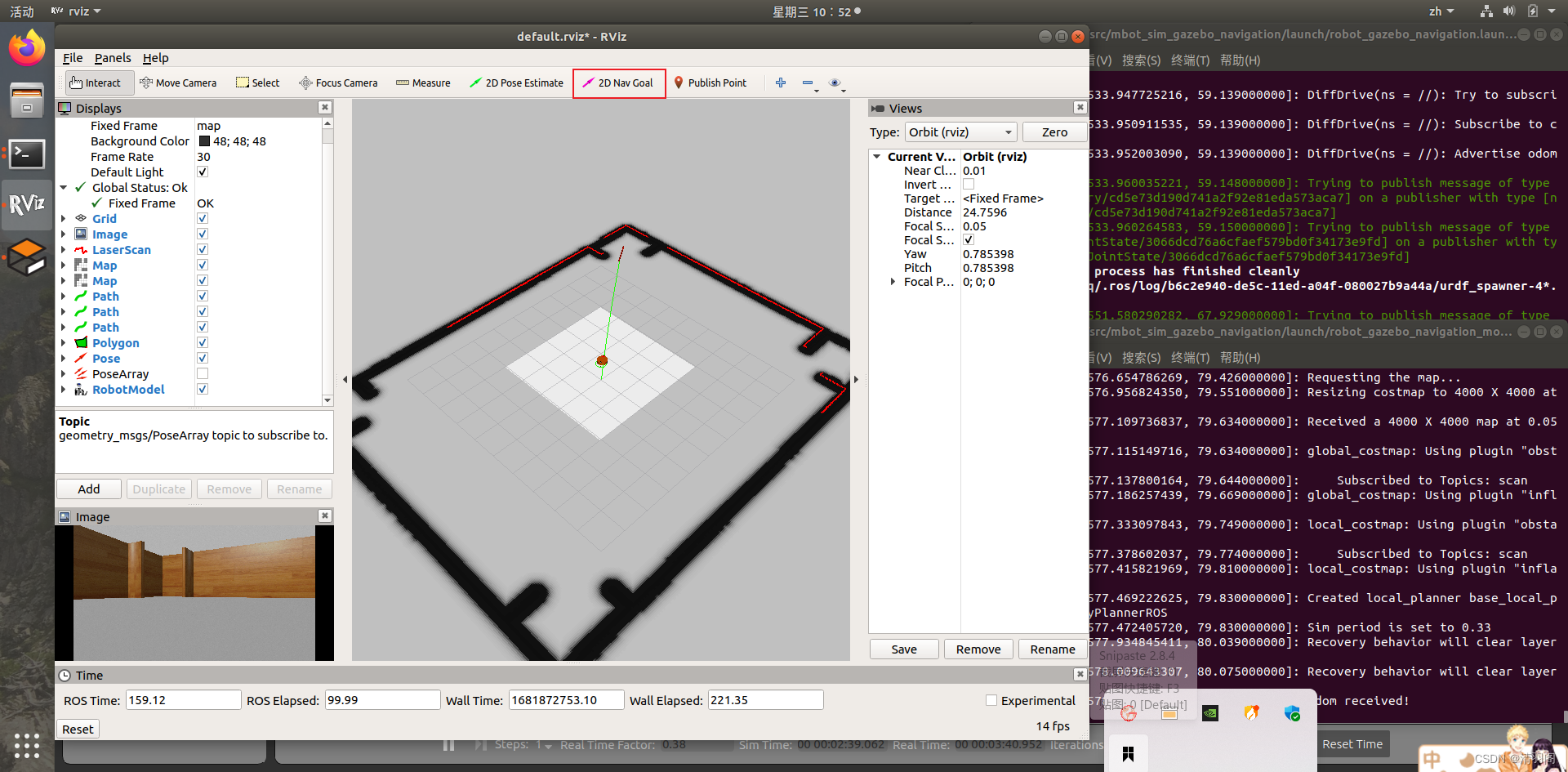
完成配置后的rviz如下图所示:
七、导航仿真
要进行导航仿真,先来看一下RVIZ中两个概念:
-
2D位姿估计
2D位姿估计允许用户初始化导航功能包集的定位系统,并设定机器人在实际环境中的位姿。导航功能包集等待名为initialpose的新主题的初始化位姿信息,这个主题是通过rviz窗口发布的。
点击2D Pose Estimate按钮,并点击地图上的某一点,就可以完成机器人的初始位姿指定。如果不进行初始化,机器人会启动一个自动定位进程并设定初始化位姿。 -
2D导航目标
2D导航目标允许用户为机器人设定一个期望位姿作为机器人的导航目标。 导航功能包集会等待名为/move_base_simple/goal的新主题的初始化目标消息。 因此, 你必须在rviz窗口Tool Properties子窗口的2D Nav Goal选项中修改主题的名称, 在主题文本框中输入新的名称/move_base_simple/goal。
单击2D Nav Goal按钮并选择地图和机器人的运动目标(你能够选择x轴和y轴坐标, 以及机器人最后的方向),可以看到机器人开始自动规划路径,并按照路径前往目标点。
因为之前设置后的RVIZ比较丑陋,我们可以再对此进行优化,此时给机器人指定目标点,机器人会前往目标点。效果如图:


 304
304


 被折叠的 条评论
为什么被折叠?
被折叠的 条评论
为什么被折叠?
 到【灌水乐园】发言


