


In this article I'm going to explain homogeneous coordinates (a.k.a. 4D coordinates) as simply as I can. In previous articles, we've used 4D vectors for matrix multiplication, but I've never really defined what the fourth dimension actually is. Now it's time to take a closer look at projective geometry.
Also, welcome back! It has been a while since my last post. Hopefully I will find some time in the next couple of months to finish up the Modern OpenGL Series of articles. The code for article 08 is done, but writing the article will take some time.
Terminology
Most of the time when working with 3D, we are thinking in terms of Euclidean geometry – that is, coordinates in three-dimensional space ( X , Y , and Z ). However, there are certain situations where it is useful to think in terms of projective geometry instead. Projective geometry has an extra dimension, called W , in addition to the X , Y , and Z dimensions. This four-dimensional space is called "projective space," and coordinates in projective space are called "homogeneous coordinates."
For the purposes of 3D software, the terms "projective" and "homogeneous" are basically interchangeable with "4D."
Not Quaternions
Quaternions look a lot like homogeneous coordinates. Both are 4D vectors, commonly depicted as (X,Y,Z,W) . However, quaternions and homogeneous coordinates are different concepts, with different uses.
The contents of this article don't apply to quaternions. If I can find the time, I might write a quaternion article in the future.
An Analogy In 2D
First, let's look at how projective geometry works in 2D, before we move on to 3D.
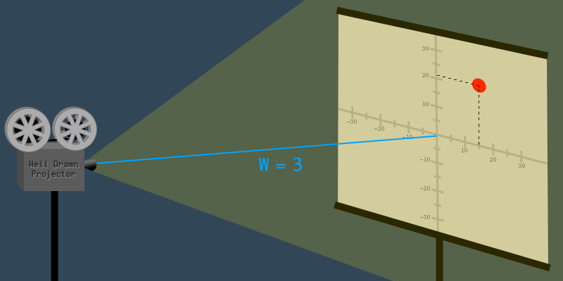
Imagine a projector that is projecting a 2D image onto a screen. It's easy to identify the X and Y dimensions of the projected image:
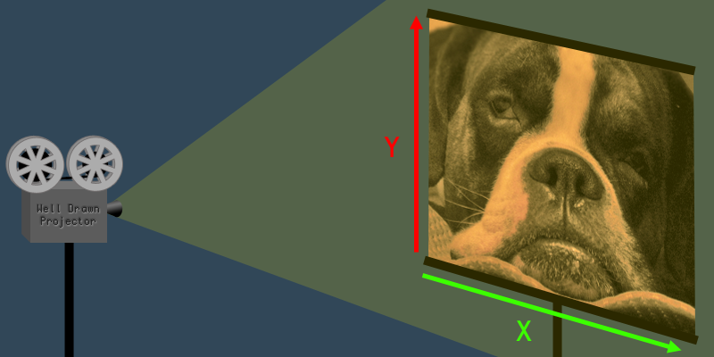
The W dimension is the distance from the projector to the screen.
Now, if you step back from the 2D image and look at the projector and the screen, you can see the W dimension too. The W dimension is the distance from the projector to the screen.
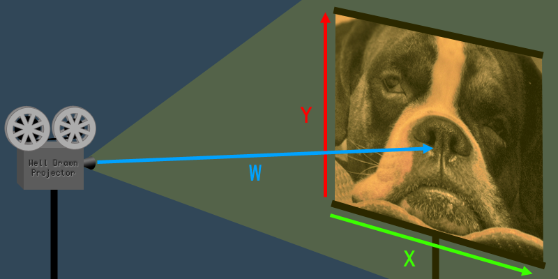
The value of W affects the size (a.k.a. scale) of the image.
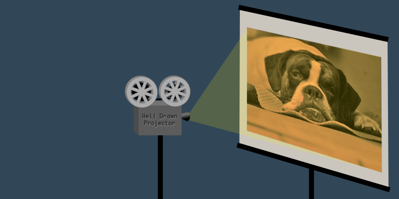
So what does the W dimension do, exactly? Imagine what would happen to the 2D image if you increased or decreased W – that is, if you increased or decreased the distance between the projector and the screen. If you move the projectorcloser to the screen, the whole 2D image becomes smaller. If you move the projector away from the screen, the 2D image becomes larger. As you can see, the value of W affects the size (a.k.a. scale) of the image.
Applying It To 3D
There is no such thing as a 3D projector (yet), so it's harder to imagine projective geometry in 3D, but the W value works exactly the same as it does in 2D. When W increases, the coordinate expands (scales up). When W decreases, the coordinate shrinks (scales down). The W is basically a scaling transformation for the 3D coordinate.
When W = 1
The usual advice for 3D programming beginners is to always set W=1 whenever converting a 3D coordinate to a 4D coordinate. The reason for this is that when you scale a coordinate by 1 it doesn't shrink or grow, it just stays the same size. So, when W=1 it has no effect on the X , Y or Z values.
For this reason, when it comes to 3D computer graphics, coordinates are said to be "correct" only when W=1 . If you rendered coordinates with W>1 then everything would look too small, and with W<1 everything would look too big. If you tried to render with W=0 your program would crash when it attempted to divide by zero. With W<0 everything would flip upside-down and back-to-front.
Mathematically speaking, there is no such thing as an "incorrect" homogeneous coordinate. Using coordinates with W=1 is just a useful convention for 3D computer graphics.
The Math
Now, let's look at some actual numbers, to see how the math works.
Let's say that the projector is 3 meters away from the screen, and there is a dot on the 2D image at the coordinate (15,21) . This gives us the projective coordinate vector (X,Y,W)=(15,21,3) .
Now, imagine that the projector was pushed closer to the screen so that the distance was 1 meter. The closer the project gets to the screen, the smaller the image becomes. The projector has moved three times closer, so the image becomes three times smaller. If we take the original coordinate vector and divide all the values by three, we get the new vector where W=1 :
The dot is now at coordinate (5,7) .
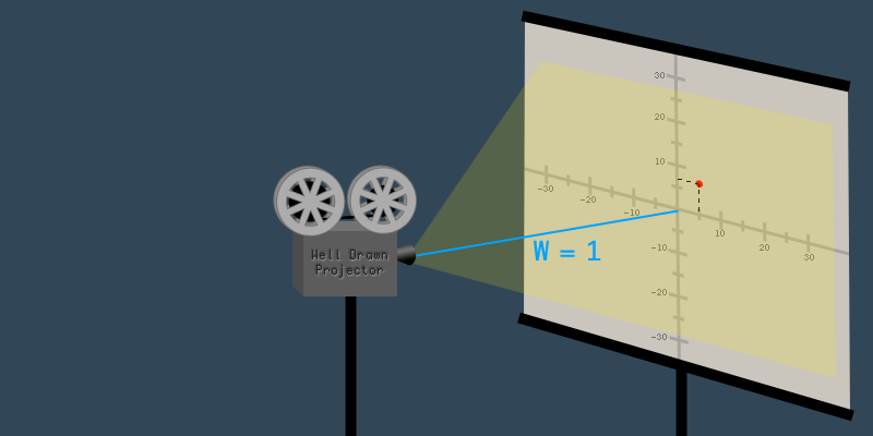
This is how an "incorrect" homogeneous coordinate is converted to a "correct" coordinate: divide all the values by W . The process is exactly the same for 2D and 3D coordinates.
Dividing all the values in a vector is done by scalar multiplication with the reciprocal of the divisor. Here is a 4D example:
Written in C++ using GLM, The example above would look like this:
glm::vec4 coordinate(10, 20, 30, 5);
glm::vec4 correctCoordinate = (1.0/coordinate.w) * coordinate;
//now, correctCoordinate == (2,4,6,1)
Uses Of Homogeneous Coordinates In Computer Graphics
As mentioned earlier, in regard to 3D computer graphics, homogeneous coordinates are useful in certain situations. We will look at some of those situations here.
Translation Matrices For 3D Coordinates
A four-column matrix can only be multiplied with a four-element vector, which is why we often use homogeneous 4D vectors instead of 3D vectors.
Rotation and scaling transformation matrices only require three columns. But, in order to do translation, the matrices need to have at least four columns. This is why transformations are often 4x4 matrices. However, a matrix with four columns can not be multiplied with a 3D vector, due to the rules of matrix multiplication. A four-column matrix can only be multiplied with a four-element vector, which is why we often use homogeneous 4D vectors instead of 3D vectors.
The 4th dimension W is usually unchanged, when using homogeneous coordinates in matrix transformation. W is set to 1 when converting a 3D coordinate into 4D, and it is usually still 1 after the transformation matrices are applied, at which point it can be converted back into a 3D coordinate by ignoring the W . This is true for all translation, rotation, and scaling transformations, which are by far the most common types of transformations. The notable exception is projection matrices, which do affect the W dimension.
Perspective Transformation
In 3D, "perspective" is the phenomenon where an object appears smaller the further away it is from the camera. A far-away mountain can appear to be smaller than a cat, if the cat is close enough to the camera.

Perspective is implemented in 3D computer graphics by using a transformation matrix that changes the W element of each vertex.
Perspective is implemented in 3D computer graphics by using a transformation matrix that changes the W element of each vertex. After the the camera matrix is applied to each vertex, but before the projection matrix is applied, the Z element of each vertex represents the distance away from the camera. Therefore, the larger Z is, the more the vertex should be scaled down. The W dimension affects the scale, so the projection matrix just changes the W value based on the Z value. Here is an example of a perspective projection matrix being applied to a homogeneous coordinate:
Notice how the W value is changed to 4 , which comes from the Z value.
Perspective division is just a specific term for converting the homogeneous coordinate back to W=1
After the perspective projection matrix is applied, each vertex undergoes "perspective division." Perspective division is just a specific term for converting the homogeneous coordinate back to W=1 , as explained earlier in the article. Continuing with the example above, the perspective division step would look like this:
After perspective division, the W value is discarded, and we are left with a 3D coordinate that has been correctly scaled according to a 3D perspective projection.
In GLM, this perspective projection matrix can be created using the glm::perspective orglm::frustum functions. In old-style OpenGL, it is commonly created with the gluPerspective orgluFrustum functions. In OpenGL, perspective division happens automatically after the vertex shader runs on each vertex. This is one reason why gl_Position, the main output of the vertex shader, is a 4D vector, not a 3D vector.
Positioning Directional Lights
One property of homogeneous coordinates is that they allow you to have points at infinity (infinite length vectors), which is not possible with 3D coordinates. Points at infinity occur when W=0 . If you try and convert a W=0 homogeneous coordinate into a normal W=1 coordinate, it results in a bunch of divide-by-zero operations:
This means that homogeneous coordinates with W=0 can not be converted into 3D coordinates.
What use does this have? Well, directional lights can be though of as point lights that are infinitely far away. When a point light is infinitely far away the rays of light become parallel, and all of the light travels in a single direction. This is basically the definition of a directional light.
If W=1 , then it is a point light. If W=0 , then it is a directional light.
So traditionally, in 3D graphics, directional lights are differentiated from point lights by the value of W in the position vector of the light. If W=1 , then it is a point light. If W=0 , then it is a directional light.
This is more of a traditional convention, rather than a useful way to write lighting code. Directional lights and point lights are usually implemented with separate code, because they behave differently. A typical lighting shader might look like this:
if(lightPosition.w == 0.0){
    //directional light code here
} else {
    //point light code here
}
Summary
Homogeneous coordinates have an extra dimension called W , which scales the X , Y , and Z dimensions. Matrices for translation and perspective projection transformations can only be applied to homogeneous coordinates, which is why they are so common in 3D computer graphics. The X , Y , and Z values are said to be "correct" when W=1 . Any homogeneous coordinate can be converted to have W=1 by dividing all four dimensions by the W value, except if W=0 . When W=0 , the coordinate represents a point at infinity (a vector with infinite length), and this is often used to denote the direction of directional lights.


 2182
2182

 被折叠的 条评论
为什么被折叠?
被折叠的 条评论
为什么被折叠?
 到【灌水乐园】发言


