


上联出口区域用ospf打通
核心A的配置:
用主设备mac地址作为两边共用的mac地址
m-lag system-mac 12e2-de9c-0104
主设备编号(两边不能一样)
m-lag system-number 1
两边的优先级必须相同
m-lag system-priority 4096
互指keepalive报文地址
m-lag keepalive ip destination 1.1.1.2 source 1.1.1.1
转发路由三层口配置IP
interface GigabitEthernet1/0/9
port link-mode route
combo enable fiber
ip address 1.1.1.1 255.255.255.252
上联路由转发路由三层口配置IP
interface GigabitEthernet1/0/8
port link-mode route
combo enable fiber
ip address 10.1.1.2 255.255.255.0
排除掉m-lag口
m-lag mad exclude interface g1/0/9
(如果使用聚合口当keepalve口,不但接口要排除,聚合口也得排除)
m-lag mad exclude interface route-aggregation 1
新建汇聚口设置为动态lacp
interface Bridge-Aggregation1
link-aggregation mode dynamic
把1/0/1和1/0/2加入到汇聚1
interface range GigabitEthernet 1/0/1 GigabitEthernet 1/0/2
port link-aggregation group 1
把聚合1的口加入到m-lag中
interface Bridge-Aggregation 1
port m-lag peer-link 1
有的设备要配置这个忽略检查mac,h3c模拟器s6850不支持这个命令,所以没做这个配置,也不影响
undo mac-address static source-check enable
创建下联口的聚合口100并设置为动态lacp模式
int Bridge-Aggregation 100
link-aggregation mode dynamic
把下联口加入到聚合组100
interface GigabitEthernet 1/0/5
port link-aggregation group 100
把下联口加入到m-lag成员组100中,两边主备要一样
interface Bridge-Aggregation 100
port m-lag group 100
增加业务vlan
vlan 10 20
interface Vlan-interface10
ip address 192.168.10.1 255.255.255.0
mac-address 0019-0016-0010
interface Vlan-interface20
ip address 192.168.20.1 255.255.255.0
mac-address 0019-0016-0020
汇聚100改为trunk口放行vlan 10 20
interface Bridge-Aggregation 100
port link-type trunk
port trunk permit vlan 10 20
发现官方教材有的要配置这两个vlan接口为M-LAG保留接口
m-lag mad exclude interface vlan-interface 10
m-lag mad exclude interface vlan-interface 20
这两条不敲,设备刚开机是好的,一会就下联聚合口两边都会down掉,具体含义下面有讲
m-lag consistency-check disable
m-lag consistency-check mode loose
undo consistency-check enable mode
命令用来恢复M-LAG配置一致性检查功能为缺省状态。
mode { strict | loose }
指定M-LAG配置一致性检查模式:
strict:严格模式。
loose:松散模式。
缺省情况下,M-LAG配置一致性检查功能处于去使能状态。
进行配置一致性检查,检查到配置不匹配时,根据配置一致性检查类型的不同,处理方式为:
当检查到Type 1类型不匹配时,不同的配置一致性检查模式处理方式为:
松散模式:打印配置一致性检查失败的日志信息。
严格模式:关闭M-LAG接口,并打印配置一致性检查失败的日志信息。
当检查到Type 2类型不匹配时,在松散模式和严格模式下,都仅打印配置一致性检查失败的日志信息。
consistency-check disable
命令用来去使能M-LAG配置一致性检查功能。
缺省情况下,M-LAG配置一致性检查功能处于去使能状态。
为保证系统正常运行,M-LAG缺省会在M-LAG系统建立过程中进行配置一致性检查。
当M-LAG系统中两台M-LAG设备因为版本升级等原因,导致M-LAG设备配置不一致。
此时,为了避免因配置一致性检查而关闭M-LAG接口,用户可以通过m-lag consistency-check disable命令关闭M-LAG配置一致性检查,保证M-LAG接口正常工作。
请用户保证两端M-LAG设备配置一致性检查功能开启状态一致
核心B的配置:
用主设备mac地址作为两边共用的mac地址
m-lag system-mac 12e2-de9c-0104
主设备编号(两边不能一样)
m-lag system-number 2
两边的优先级必须相同
m-lag system-priority 4096
互指keepalive报文地址
m-lag keepalive ip destination 1.1.1.2 source 1.1.1.1
转发路由三层口配置IP
interface GigabitEthernet1/0/9
port link-mode route
combo enable fiber
ip address 1.1.1.1 255.255.255.252
上联路由转发路由三层口配置IP
interface GigabitEthernet1/0/8
port link-mode route
combo enable fiber
ip address 10.1.1.2 255.255.255.0
排除掉m-lag口
m-lag mad exclude interface g1/0/9
(如果使用聚合口当keepalve口,不但接口要排除,聚合口也得排除)
m-lag mad exclude interface route-aggregation 1
新建汇聚口设置为动态lacp
interface Bridge-Aggregation1
link-aggregation mode dynamic
把1/0/1和1/0/2加入到汇聚1
interface range GigabitEthernet 1/0/1 GigabitEthernet 1/0/2
port link-aggregation group 1
把聚合1的口加入到m-lag中
interface Bridge-Aggregation 1
port m-lag peer-link 1
有的设备要配置这个忽略检查mac,h3c模拟器s6850不支持这个命令,所以没做这个配置,也不影响
undo mac-address static source-check enable
创建下联口的聚合口100并设置为动态lacp模式
int Bridge-Aggregation 100
link-aggregation mode dynamic
把下联口加入到聚合组100
interface GigabitEthernet 1/0/5
port link-aggregation group 100
把下联口加入到m-lag成员100中,主备设备必须要一样
interface Bridge-Aggregation 100
port m-lag group 100
增加业务vlan
vlan 10 20
interface Vlan-interface10
ip address 192.168.10.1 255.255.255.0
mac-address 0019-0016-0010
interface Vlan-interface20
ip address 192.168.20.1 255.255.255.0
mac-address 0019-0016-0020
汇聚100改为trunk口放行vlan 10 20
interface Bridge-Aggregation 100
port link-type trunk
port trunk permit vlan 10 20
发现官方教材有的要配置这两个vlan接口为M-LAG保留接口
m-lag mad exclude interface vlan-interface 10
m-lag mad exclude interface vlan-interface 20
这两条不敲,设备刚开机是好的,一会就下联聚合口两边都会down掉,具体信义下面有讲
m-lag consistency-check disable
m-lag consistency-check mode loose
undo consistency-check enable mode
命令用来恢复M-LAG配置一致性检查功能为缺省状态。
mode { strict | loose }
指定M-LAG配置一致性检查模式:
strict:严格模式。
loose:松散模式。
缺省情况下,M-LAG配置一致性检查功能处于去使能状态。
进行配置一致性检查,检查到配置不匹配时,根据配置一致性检查类型的不同,处理方式为:
当检查到Type 1类型不匹配时,不同的配置一致性检查模式处理方式为:
松散模式:打印配置一致性检查失败的日志信息。
严格模式:关闭M-LAG接口,并打印配置一致性检查失败的日志信息。
当检查到Type 2类型不匹配时,在松散模式和严格模式下,都仅打印配置一致性检查失败的日志信息。
consistency-check disable
命令用来去使能M-LAG配置一致性检查功能。
缺省情况下,M-LAG配置一致性检查功能处于去使能状态。
为保证系统正常运行,M-LAG缺省会在M-LAG系统建立过程中进行配置一致性检查。
当M-LAG系统中两台M-LAG设备因为版本升级等原因,导致M-LAG设备配置不一致。
此时,为了避免因配置一致性检查而关闭M-LAG接口,用户可以通过m-lag consistency-check disable命令关闭M-LAG配置一致性检查,保证M-LAG接口正常工作。
请用户保证两端M-LAG设备配置一致性检查功能开启状态一致
接入交换机配置(和普通的配法一样):
vlan 10 20
interface GigabitEthernet 1/0/1
port link-type access
port access vlan 10
interface GigabitEthernet 1/0/2
port link-type access
port access vlan 20
建立上联连接的汇聚并设置为lacp动态
interface Bridge-Aggregation 100
link-aggregation mode dynamic
把上联两个口子加入到汇聚100
interface range GigabitEthernet 1/0/5 g1/0/6
port link-aggregation group 100
汇聚100改为trunk口放行vlan 10 20
interface Bridge-Aggregation 100
port link-type trunk
port trunk permit vlan 10 20
主要设备具体配置命令:
路由器:
dis current-configuration
version 7.1.064, Release 0427P22
sysname H3C
ospf 1 router-id 66.66.66.66
default-route-advertise always
import-route direct
area 0.0.0.0
network 16.1.1.0 0.0.0.255
network 26.1.1.0 0.0.0.255
vlan 1
interface LoopBack0
ip address 11.1.1.1 255.255.255.255
interface GigabitEthernet0/0
port link-mode route
combo enable copper
ip address 16.1.1.1 255.255.255.0
interface GigabitEthernet0/1
port link-mode route
combo enable copper
ip address 26.1.1.1 255.255.255.0
核心1(左边):
<HX_A>dis current-configuration
version 7.1.070, Alpha 7170
sysname HX_A
ospf 1 router-id 11.11.11.11
import-route direct
area 0.0.0.0
network 16.1.1.0 0.0.0.255
vlan 1
vlan 10
vlan 20
stp global enable
interface Bridge-Aggregation1
port link-type trunk
port trunk permit vlan all
link-aggregation mode dynamic
port m-lag peer-link 1
interface Bridge-Aggregation100
port link-type trunk
port trunk permit vlan 1 10 20
link-aggregation mode dynamic
port m-lag group 100
interface NULL0
interface Vlan-interface10
ip address 192.168.10.1 255.255.255.0
mac-address 0019-0016-0010
interface Vlan-interface20
ip address 192.168.20.1 255.255.255.0
mac-address 0019-0016-0020
interface GigabitEthernet1/0/8
port link-mode route
combo enable fiber
ip address 16.1.1.2 255.255.255.0
interface GigabitEthernet1/0/9
port link-mode route
combo enable fiber
ip address 1.1.1.1 255.255.255.252
interface GigabitEthernet1/0/1
port link-mode bridge
port link-type trunk
port trunk permit vlan all
combo enable fiber
port link-aggregation group 1
interface GigabitEthernet1/0/2
port link-mode bridge
port link-type trunk
port trunk permit vlan all
combo enable fiber
port link-aggregation group 1
interface GigabitEthernet1/0/5
port link-mode bridge
port link-type trunk
port trunk permit vlan 1 10 20
combo enable fiber
port link-aggregation group 100
m-lag mad exclude interface GigabitEthernet1/0/9
m-lag mad exclude interface Vlan-interface10
m-lag mad exclude interface Vlan-interface20
m-lag system-mac 12e2-de9c-0104
m-lag system-number 1
m-lag system-priority 4096
m-lag consistency-check disable
m-lag consistency-check mode loose
m-lag keepalive ip destination 1.1.1.2 source 1.1.1.1
核心2(右边)
<HX_B>dis current-configuration
version 7.1.070, Alpha 7170
sysname HX_B
ospf 1 router-id 22.22.22.22
import-route direct
area 0.0.0.0
network 26.1.1.0 0.0.0.255
vlan 1
vlan 10
vlan 20
stp global enable
interface Bridge-Aggregation1
port link-type trunk
port trunk permit vlan all
link-aggregation mode dynamic
port m-lag peer-link 1
interface Bridge-Aggregation100
port link-type trunk
port trunk permit vlan 1 10 20
link-aggregation mode dynamic
port m-lag group 100
interface NULL0
interface Vlan-interface10
ip address 192.168.10.1 255.255.255.0
mac-address 0019-0016-0010
interface Vlan-interface20
ip address 192.168.20.1 255.255.255.0
mac-address 0019-0016-0020
interface GigabitEthernet1/0/8
port link-mode route
combo enable fiber
ip address 26.1.1.2 255.255.255.0
interface GigabitEthernet1/0/9
port link-mode route
combo enable fiber
ip address 1.1.1.2 255.255.255.252
interface GigabitEthernet1/0/1
port link-mode bridge
port link-type trunk
port trunk permit vlan all
combo enable fiber
port link-aggregation group 1
interface GigabitEthernet1/0/2
port link-mode bridge
port link-type trunk
port trunk permit vlan all
combo enable fiber
port link-aggregation group 1
interface GigabitEthernet1/0/5
port link-mode bridge
port link-type trunk
port trunk permit vlan 1 10 20
combo enable fiber
port link-aggregation group 100
m-lag mad exclude interface GigabitEthernet1/0/9
m-lag mad exclude interface Vlan-interface10
m-lag mad exclude interface Vlan-interface20
m-lag system-mac 12e2-de9c-0104
m-lag system-number 2
m-lag system-priority 4096
m-lag consistency-check disable
m-lag consistency-check mode loose
m-lag keepalive ip destination 1.1.1.1 source 1.1.1.2
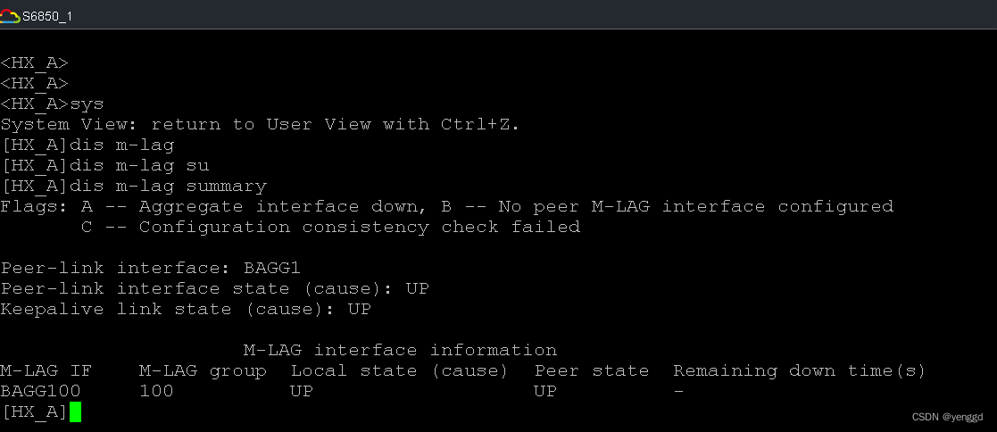
核心A看到的:

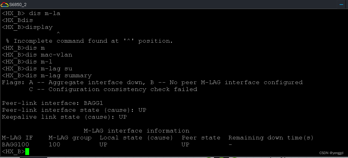
核心B看到的:
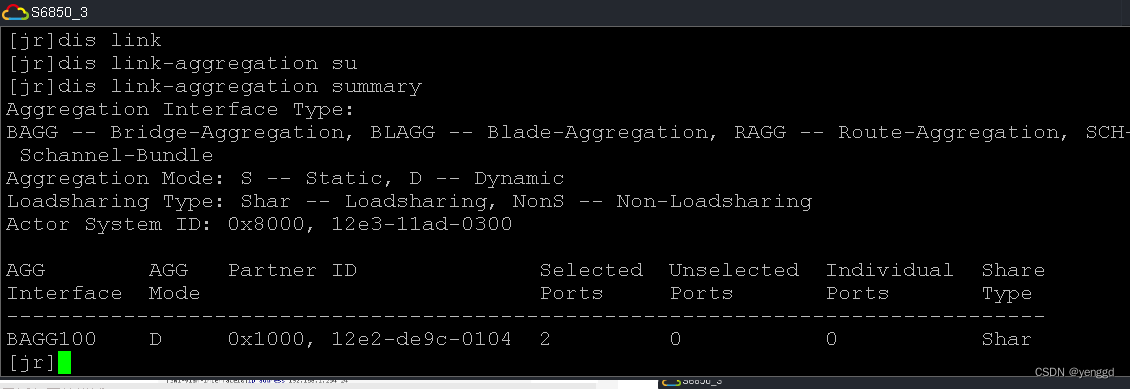
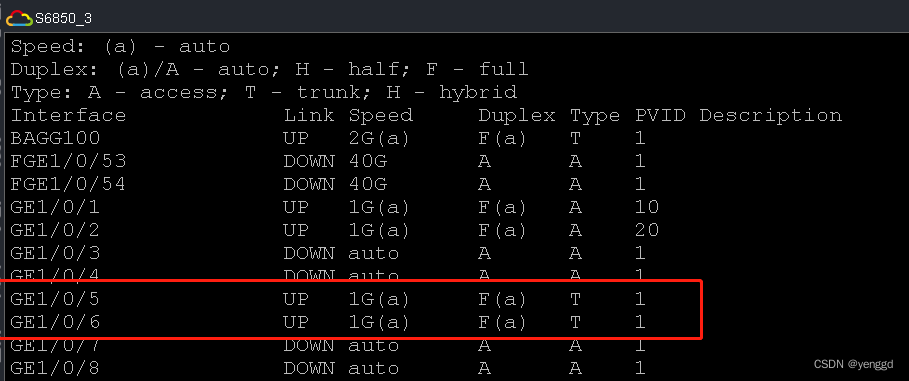
接入交换机查看聚合口
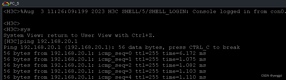
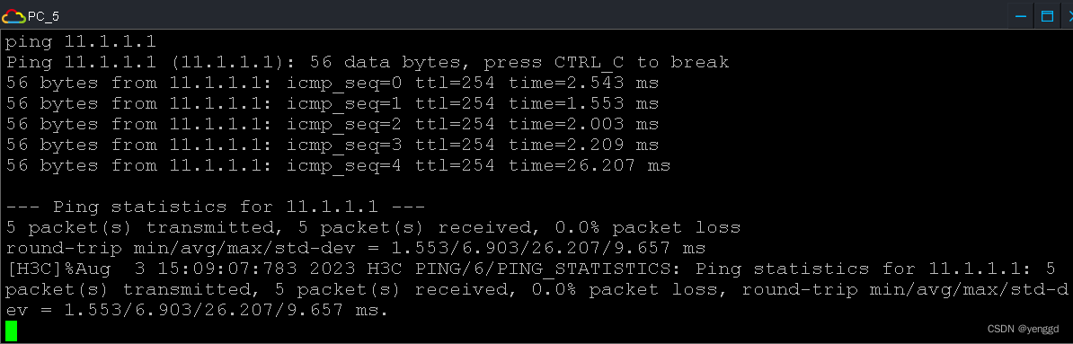
PC5
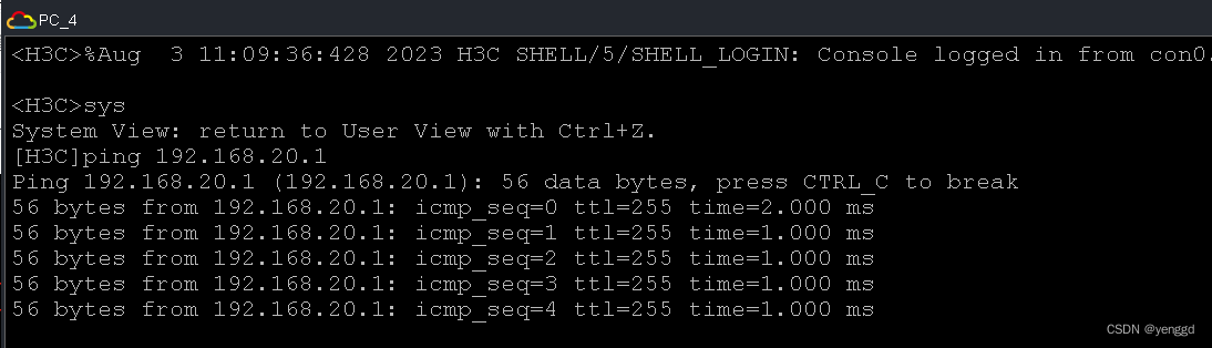
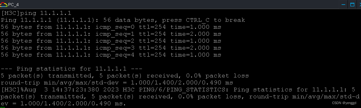
PC4
以下是参考官方教材:
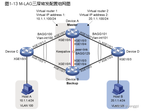
配置步骤
(1) 配置Device A
系统配置。
system-view
[DeviceA] m-lag system-mac 1-1-1
[DeviceA] m-lag system-number 1
[DeviceA] m-lag system-priority 123
配置Keepalive报文的目的IP地址和源IP地址。
[DeviceA] m-lag keepalive ip destination 1.1.1.2 source 1.1.1.1
配置端口Ten-GigabitEthernet1/0/5工作在三层模式,并配置IP地址为Keepalive报文的源IP地址。
[DeviceA] interface ten-gigabitethernet 1/0/5
[DeviceA-Ten-GigabitEthernet1/0/5] port link-mode route
[DeviceA-Ten-GigabitEthernet1/0/5] ip address 1.1.1.1 24
[DeviceA-Ten-GigabitEthernet1/0/5] quit
配置Keepalive链路接口为M-LAG保留接口。
[DeviceA] m-lag mad exclude interface ten-gigabitethernet 1/0/5
创建动态二层聚合接口125。
[DeviceA] interface bridge-aggregation 125
[DeviceA-Bridge-Aggregation125] link-aggregation mode dynamic
[DeviceA-Bridge-Aggregation125] quit
分别将端口Ten-GigabitEthernet1/0/3和Ten-GigabitEthernet1/0/4加入到聚合组125中。
[DeviceA] interface ten-gigabitethernet 1/0/3
[DeviceA-Ten-GigabitEthernet1/0/3] port link-aggregation group 125
[DeviceA-Ten-GigabitEthernet1/0/3] quit
[DeviceA] interface ten-gigabitethernet 1/0/4
[DeviceA-Ten-GigabitEthernet1/0/4] port link-aggregation group 125
[DeviceA-Ten-GigabitEthernet1/0/4] quit
配置二层聚合接口125为peer-link接口。
[DeviceA] interface bridge-aggregation 125
[DeviceA-Bridge-Aggregation125] port m-lag peer-link 1
[DeviceA-Bridge-Aggregation125] undo mac-address static source-check enable
[DeviceA-Bridge-Aggregation125] quit
创建动态二层聚合接口100,并配置该接口为M-LAG接口1。
[DeviceA] interface bridge-aggregation 100
[DeviceA-Bridge-Aggregation100] link-aggregation mode dynamic
[DeviceA-Bridge-Aggregation100] port m-lag group 1
[DeviceA-Bridge-Aggregation100] quit
将端口Ten-GigabitEthernet1/0/1加入到聚合组100中。
[DeviceA] interface ten-gigabitethernet 1/0/1
[DeviceA-Ten-GigabitEthernet1/0/1] port link-aggregation group 100
[DeviceA-Ten-GigabitEthernet1/0/1] quit
创建动态二层聚合接口101,并配置该接口为M-LAG接口2。
[DeviceA] interface bridge-aggregation 101
[DeviceA-Bridge-Aggregation101] link-aggregation mode dynamic
[DeviceA-Bridge-Aggregation101] port m-lag group 2
[DeviceA-Bridge-Aggregation101] quit
将端口Ten-GigabitEthernet1/0/2加入到聚合组101中。
[DeviceA] interface ten-gigabitethernet 1/0/2
[DeviceA-Ten-GigabitEthernet1/0/2] port link-aggregation group 101
[DeviceA-Ten-GigabitEthernet1/0/2] quit
创建VLAN 100和101。
[DeviceA] vlan 100
[DeviceA-vlan100] quit
[DeviceA] vlan 101
[DeviceA-vlan101] quit
配置二层聚合接口100为Trunk端口,并允许VLAN 100的报文通过。
[DeviceA] interface bridge-aggregation 100
[DeviceA-Bridge-Aggregation100] port link-type trunk
[DeviceA-Bridge-Aggregation100] port trunk permit vlan 100
[DeviceA-Bridge-Aggregation100] quit
配置二层聚合接口101为Trunk端口,并允许VLAN 101的报文通过。
[DeviceA] interface bridge-aggregation 101
[DeviceA-Bridge-Aggregation101] port link-type trunk
[DeviceA-Bridge-Aggregation101] port trunk permit vlan 101
[DeviceA-Bridge-Aggregation101] quit
创建接口Vlan-interface100和Vlan-interface101,并配置其IP地址。
[DeviceA] interface vlan-interface 100
[DeviceA-vlan-interface100] ip address 10.1.1.1 24
[DeviceA-vlan-interface100] quit
[DeviceA] interface vlan-interface 101
[DeviceA-vlan-interface101] ip address 20.1.1.1 24
[DeviceA-vlan-interface101] quit
配置Vlan-interface100和Vlan-interface101接口为M-LAG保留接口。
[DeviceA] m-lag mad exclude interface vlan-interface 100
[DeviceA] m-lag mad exclude interface vlan-interface 101
配置OSPF。
[DeviceA] ospf
[DeviceA-ospf-1] import-route direct
[DeviceA-ospf-1] area 0
[DeviceA-ospf-1-area-0.0.0.0] network 10.1.1.0 0.0.0.255
[DeviceA-ospf-1-area-0.0.0.0] network 20.1.1.0 0.0.0.255
[DeviceA-ospf-1-area-0.0.0.0] quit
[DeviceA-ospf-1] quit
为接口Vlan-interface100创建备份组1,并配置备份组1的虚拟IP地址为10.1.1.100。
[DeviceA] interface vlan-interface 100
[DeviceA-Vlan-interface100] vrrp vrid 1 virtual-ip 10.1.1.100
设置Device A在备份组1中的优先级为200,以保证Device A成为Master负责转发流量。
[DeviceA-Vlan-interface100] vrrp vrid 1 priority 200
[DeviceA-Vlan-interface100] quit
为接口Vlan-interface101创建备份组2,并配置备份组2的虚拟IP地址为20.1.1.100。
[DeviceA] interface vlan-interface 101
[DeviceA-Vlan-interface101] vrrp vrid 2 virtual-ip 20.1.1.100
设置Device A在备份组2中的优先级为200,以保证Device A成为Master负责转发流量。
[DeviceA-Vlan-interface101] vrrp vrid 2 priority 200
[DeviceA-Vlan-interface101] quit
(2) 配置Device B
系统配置。
system-view
[DeviceB] m-lag system-mac 1-1-1
[DeviceB] m-lag system-number 2
[DeviceB] m-lag system-priority 123
配置Keepalive报文的目的IP地址和源IP地址。
[DeviceB] m-lag keepalive ip destination 1.1.1.1 source 1.1.1.2
配置端口Ten-GigabitEthernet1/0/5工作在三层模式,并配置IP地址为Keepalive报文的源IP地址。
[DeviceB] interface ten-gigabitethernet 1/0/5
[DeviceB-Ten-GigabitEthernet1/0/5] port link-mode route
[DeviceB-Ten-GigabitEthernet1/0/5] ip address 1.1.1.2 24
[DeviceB-Ten-GigabitEthernet1/0/5] quit
配置Keepalive链路接口为M-LAG保留接口。
[DeviceB] m-lag mad exclude interface ten-gigabitethernet 1/0/5
创建动态二层聚合接口125。
[DeviceB] interface bridge-aggregation 125
[DeviceB-Bridge-Aggregation125] link-aggregation mode dynamic
[DeviceB-Bridge-Aggregation125] quit
分别将端口Ten-GigabitEthernet1/0/3和Ten-GigabitEthernet1/0/4加入到聚合组125中。
[DeviceB] interface ten-gigabitethernet 1/0/3
[DeviceB-Ten-GigabitEthernet1/0/3] port link-aggregation group 125
[DeviceB-Ten-GigabitEthernet1/0/3] quit
[DeviceB] interface ten-gigabitethernet 1/0/4
[DeviceB-Ten-GigabitEthernet1/0/4] port link-aggregation group 125
[DeviceB-Ten-GigabitEthernet1/0/4] quit
配置二层聚合接口125为peer-link接口。
[DeviceB] interface bridge-aggregation 125
[DeviceB-Bridge-Aggregation125] port m-lag peer-link 1
[DeviceB-Bridge-Aggregation125] undo mac-address static source-check enable
[DeviceB-Bridge-Aggregation125] quit
创建动态二层聚合接口100,并配置该接口为M-LAG接口1。
[DeviceB] interface bridge-aggregation 100
[DeviceB-Bridge-Aggregation100] link-aggregation mode dynamic
[DeviceB-Bridge-Aggregation100] port m-lag group 1
[DeviceB-Bridge-Aggregation100] quit
将端口Ten-GigabitEthernet1/0/1加入到聚合组100中。
[DeviceB] interface ten-gigabitethernet 1/0/1
[DeviceB-Ten-GigabitEthernet1/0/1] port link-aggregation group 100
[DeviceB-Ten-GigabitEthernet1/0/1] quit
创建动态二层聚合接口101,并配置该接口为M-LAG接口2。
[DeviceB] interface bridge-aggregation 101
[DeviceB-Bridge-Aggregation101] link-aggregation mode dynamic
[DeviceB-Bridge-Aggregation101] port m-lag group 2
[DeviceB-Bridge-Aggregation101] quit
将端口Ten-GigabitEthernet1/0/2加入到聚合组101中。
[DeviceB] interface ten-gigabitethernet 1/0/2
[DeviceB-Ten-GigabitEthernet1/0/2] port link-aggregation group 101
[DeviceB-Ten-GigabitEthernet1/0/2] quit
创建VLAN 100和101。
[DeviceB] vlan 100
[DeviceB-vlan100] quit
[DeviceB] vlan 101
[DeviceB-vlan101] quit
配置二层聚合接口100为Trunk端口,并允许VLAN 100的报文通过。
[DeviceB] interface bridge-aggregation 100
[DeviceB-Bridge-Aggregation100] port link-type trunk
[DeviceB-Bridge-Aggregation100] port trunk permit vlan 100
[DeviceB-Bridge-Aggregation100] quit
配置二层聚合接口101为Trunk端口,并允许VLAN 101的报文通过。
[DeviceB] interface bridge-aggregation 101
[DeviceB-Bridge-Aggregation101] port link-type trunk
[DeviceB-Bridge-Aggregation101] port trunk permit vlan 101
[DeviceB-Bridge-Aggregation101] quit
配置二层聚合接口125为Trunk端口,并允许VLAN 100和101的报文通过。
[DeviceB] interface bridge-aggregation 125
[DeviceB-Bridge-Aggregation125] port link-type trunk
[DeviceB-Bridge-Aggregation125] port trunk permit vlan 100 101
[DeviceB-Bridge-Aggregation125] quit
创建接口Vlan-interface100和Vlan-interface101,并配置其IP地址。
[DeviceB] interface vlan-interface 100
[DeviceB-vlan-interface100] ip address 10.1.1.2 24
[DeviceB-vlan-interface100] quit
[DeviceB] interface vlan-interface 101
[DeviceB-vlan-interface101] ip address 20.1.1.2 24
[DeviceB-vlan-interface101] quit
配置Vlan-interface100和Vlan-interface101接口为M-LAG保留接口。
[DeviceB] m-lag mad exclude interface vlan-interface 100
[DeviceB] m-lag mad exclude interface vlan-interface 101
配置OSPF。
[DeviceB] ospf
[DeviceB-ospf-1] import-route direct
[DeviceB-ospf-1] area 0
[DeviceB-ospf-1-area-0.0.0.0] network 10.1.1.0 0.0.0.255
[DeviceB-ospf-1-area-0.0.0.0] network 20.1.1.0 0.0.0.255
[DeviceB-ospf-1-area-0.0.0.0] quit
[DeviceB-ospf-1] quit
为接口Vlan-interface100创建备份组1,并配置备份组1的虚拟IP地址为10.1.1.100。
[DeviceB] interface vlan-interface 100
[DeviceB-Vlan-interface100] vrrp vrid 1 virtual-ip 10.1.1.100
[DeviceB-Vlan-interface100] quit
为接口Vlan-interface101创建备份组2,并配置备份组2的虚拟IP地址为20.1.1.100。
[DeviceB] interface vlan-interface 101
[DeviceB-Vlan-interface101] vrrp vrid 2 virtual-ip 20.1.1.100
[DeviceB-Vlan-interface101] quit
(3) 配置Device C
创建二层聚合接口100,并配置该接口为动态聚合模式。
system-view
[DeviceC] interface bridge-aggregation 100
[DeviceC-Bridge-Aggregation100] link-aggregation mode dynamic
[DeviceC-Bridge-Aggregation100] quit
分别将端口Ten-GigabitEthernet1/0/1和Ten-GigabitEthernet1/0/2加入到聚合组100中。
[DeviceC] interface range ten-gigabitethernet 1/0/1 to ten-gigabitethernet 1/0/2
[DeviceC-if-range] port link-aggregation group 100
[DeviceC-if-range] quit
创建VLAN 100。
[DeviceC] vlan 100
[DeviceC-vlan100] quit
配置二层聚合接口100为Trunk端口,并允许VLAN 100的报文通过。
[DeviceC] interface bridge-aggregation 100
[DeviceC-Bridge-Aggregation100] port link-type trunk
[DeviceC-Bridge-Aggregation100] port trunk permit vlan 100
[DeviceC-Bridge-Aggregation100] quit
配置接口Ten-GigabitEthernet1/0/3为Trunk端口,并允许VLAN 100的报文通过。
[DeviceC] interface ten-gigabitethernet 1/0/3
[DeviceC-Ten-GigabitEthernet1/0/3] port link-type trunk
[DeviceC-Ten-GigabitEthernet1/0/3] port trunk permit vlan 100
[DeviceC-Ten-GigabitEthernet1/0/3] quit
创建接口Vlan-interface100,并配置其IP地址。
[DeviceC] interface vlan-interface 100
[DeviceC-vlan-interface100] ip address 10.1.1.3 24
[DeviceC-vlan-interface100] quit
配置OSPF。
[DeviceC] ospf
[DeviceC-ospf-1] import-route direct
[DeviceC-ospf-1] area 0
[DeviceC-ospf-1-area-0.0.0.0] network 10.1.1.0 0.0.0.255
[DeviceC-ospf-1-area-0.0.0.0] quit
[DeviceC-ospf-1] quit
(4) 配置Device D
创建二层聚合接口101,并配置该接口为动态聚合模式。
system-view
[DeviceD] interface bridge-aggregation 101
[DeviceD-Bridge-Aggregation101] link-aggregation mode dynamic
[DeviceD-Bridge-Aggregation101] quit
分别将端口Ten-GigabitEthernet1/0/1和Ten-GigabitEthernet1/0/2加入到聚合组101中。
[DeviceD] interface range ten-gigabitethernet 1/0/1 to ten-gigabitethernet 1/0/2
[DeviceD-if-range] port link-aggregation group 101
[DeviceD-if-range] quit
创建VLAN 101。
[DeviceD] vlan 101
[DeviceD-vlan101] quit
配置二层聚合接口101为Trunk端口,并允许VLAN 101的报文通过。
[DeviceD] interface bridge-aggregation 101
[DeviceD-Bridge-Aggregation101] port link-type trunk
[DeviceD-Bridge-Aggregation101] port trunk permit vlan 101
[DeviceD-Bridge-Aggregation101] quit
配置接口Ten-GigabitEthernet1/0/3为Trunk端口,并允许VLAN 101的报文通过。
[DeviceD] interface ten-gigabitethernet 1/0/3
[DeviceD-Ten-GigabitEthernet1/0/3] port link-type trunk
[DeviceD-Ten-GigabitEthernet1/0/3] port trunk permit vlan 101
[DeviceD-Ten-GigabitEthernet1/0/3] quit
创建接口Vlan-interface101,并配置其IP地址。
[DeviceD] interface vlan-interface 101
[DeviceD-vlan-interface101] ip address 20.1.1.3 24
[DeviceD-vlan-interface101] quit
配置OSPF。
[DeviceD] ospf
[DeviceD-ospf-1] import-route direct
[DeviceD-ospf-1] area 0
[DeviceD-ospf-1-area-0.0.0.0] network 20.1.1.0 0.0.0.255
[DeviceD-ospf-1-area-0.0.0.0] quit
[DeviceD-ospf-1] quit
- 验证配置
查看Device C上的OSPF邻居信息。
[DeviceC] display ospf peer
     OSPF Process 1 with Router ID 10.1.1.3

           Neighbor Brief Information
Area: 0.0.0.0
Router ID Address Pri Dead-Time State Interface
20.1.1.1 10.1.1.1 1 37 Full/DR Vlan100
20.1.1.2 10.1.1.2 1 32 Full/BDR Vlan100
以上信息表明Device C与Device A和Device B分别建立OSPF邻居。
查看Device D上的OSPF邻居信息。
[DeviceD] display ospf peer
     OSPF Process 1 with Router ID 20.1.1.3

           Neighbor Brief Information
Area: 0.0.0.0
Router ID Address Pri Dead-Time State Interface
20.1.1.1 20.1.1.1 1 38 Full/DR Vlan101
20.1.1.2 20.1.1.2 1 37 Full/BDR Vlan101
以上信息表明Device D与Device A和Device B分别建立OSPF邻居。


 2040
2040

 被折叠的 条评论
为什么被折叠?
被折叠的 条评论
为什么被折叠?
 到【灌水乐园】发言


