


Games101-作业3(管线分析、深度插值、libpng warning、双线性插值等)
在前两次作业的基础上,添加光照模型和材质处理。
以下内容参考了论坛和博客。
渲染管线
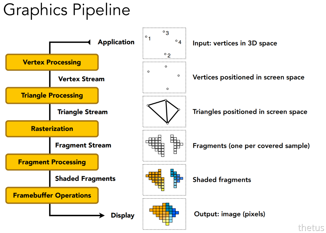
在Shading中,闫老师讲了图形管线的一系列操作,概括下来如下:
- Vertex Processing 点操作 :将三维空间上的点投影到二维
- Triangle Processing 三角形操作 :将三个点连成一个三角形/线,构造出一个平面/线,使得原三维空间物体变成由若干三角形组成的物体
- Raserization 光栅化:进行离散化的采样,用像素表示采样结果
- Fragment Processing 片元处理 :着色
- Framebuffer Operations片元缓冲操作:根据深度信息,确定遮挡和可视情况
下面我就按照管线的顺序,理一下整个流程,记录在注释里。
1.主函数main()
int main(int argc, const char** argv)
{
    //记录组成三维图形的所有小三角形
    std::vector<Triangle*> TriangleList;

    float angle = 140.0;
    bool command_line = false;

    std::string filename = "output.png";
    objl::Loader Loader;
    std::string obj_path = "../models/spot/";

    // Load .obj File
    bool loadout = Loader.LoadFile("../models/spot/spot_triangulated_good.obj");
    for(auto mesh:Loader.LoadedMeshes)
    {
        //对于图形中的每个面(即一个小三角形)的三个点记录在一起
        for(int i=0;i<mesh.Vertices.size();i+=3)
        {
            //用Triangle类,记录一个小三角形的三个顶点的信息:
            //setVertex顶点位置,setNormal顶点的法线,setTexCoord顶点对应的纹理
            Triangle* t = new Triangle();
            for(int j=0;j<3;j++)
            {
                t->setVertex(j,Vector4f(mesh.Vertices[i+j].Position.X,mesh.Vertices[i+j].Position.Y,mesh.Vertices[i+j].Position.Z,1.0));
                t->setNormal(j,Vector3f(mesh.Vertices[i+j].Normal.X,mesh.Vertices[i+j].Normal.Y,mesh.Vertices[i+j].Normal.Z));
                t->setTexCoord(j,Vector2f(mesh.Vertices[i+j].TextureCoordinate.X, mesh.Vertices[i+j].TextureCoordinate.Y));
            }
            TriangleList.push_back(t);
        }
    }

    //初始化光栅化对象,定义屏幕长宽
    rst::rasterizer r(700, 700);


    //记录纹理到对象,注意rasterizer.hpp类有属性 optional<Texture> texture
    auto texture_path = "hmap.jpg";
    r.set_texture(Texture(obj_path + texture_path));

    //记录片元处理方式,类似于“赋值函数”,现默认方式是phong
    std::function<Eigen::Vector3f(fragment_shader_payload)> active_shader = phong_fragment_shader;


    //处理传入的参数,注意在此处根据调用方式不同,修改了rasterizer对象的片元处理方式!
    if (argc >= 2)
    {
        command_line = true;
        filename = std::string(argv[1]);

        if (argc == 3 && std::string(argv[2]) == "texture")
        {
            std::cout << "Rasterizing using the texture shader\n";
            active_shader = texture_fragment_shader;
            texture_path = "spot_texture.png";
            r.set_texture(Texture(obj_path + texture_path));
        }
        else if (argc == 3 && std::string(argv[2]) == "normal")
        {
            std::cout << "Rasterizing using the normal shader\n";
            active_shader = normal_fragment_shader;
        }
        else if (argc == 3 && std::string(argv[2]) == "phong")
        {
            std::cout << "Rasterizing using the phong shader\n";
            active_shader = phong_fragment_shader;
        }
        else if (argc == 3 && std::string(argv[2]) == "bump")
        {
            std::cout << "Rasterizing using the bump shader\n";
            active_shader = bump_fragment_shader;
        }
        else if (argc == 3 && std::string(argv[2]) == "displacement")
        {
            std::cout << "Rasterizing using the bump shader\n";
            active_shader = displacement_fragment_shader;
        }
    }

    //人眼所在位置
    Eigen::Vector3f eye_pos = {0,0,10};

    //设置顶点着色方式,获取顶点位置
    r.set_vertex_shader(vertex_shader);

    //设置片元着色方式,根据调用方式不同已赋值到active_shader
    r.set_fragment_shader(active_shader);

    //修改这个值,可以选择输出图片或动态旋转渲染的模型
    int key = 0;
    int frame_count = 0;

    if (command_line)
    {

        //清空两个缓冲区,在最后处理遮挡显示情况时发挥作用
        r.clear(rst::Buffers::Color | rst::Buffers::Depth);

        //分别设置MVP矩阵,用于对点操作,实现将三维的点映射到平面
        r.set_model(get_model_matrix(angle));
        r.set_view(get_view_matrix(eye_pos));
        r.set_projection(get_projection_matrix(45.0, 1, 0.1, 50));


        // 应用变换矩阵 并进行光栅化、片元处理、帧缓冲
        r.draw(TriangleList);


        cv::Mat image(700, 700, CV_32FC3, r.frame_buffer().data());
        image.convertTo(image, CV_8UC3, 1.0f);
        cv::cvtColor(image, image, cv::COLOR_RGB2BGR);

        cv::imwrite(filename, image);

        return 0;
    }

    while(key != 27)
    {
        r.clear(rst::Buffers::Color | rst::Buffers::Depth);

        r.set_model(get_model_matrix(angle));
        r.set_view(get_view_matrix(eye_pos));
        r.set_projection(get_projection_matrix(45.0, 1, 0.1, 50));

        //r.draw(pos_id, ind_id, col_id, rst::Primitive::Triangle);
        r.draw(TriangleList);
        cv::Mat image(700, 700, CV_32FC3, r.frame_buffer().data());
        image.convertTo(image, CV_8UC3, 1.0f);
        cv::cvtColor(image, image, cv::COLOR_RGB2BGR);

        cv::imshow("image", image);
        cv::imwrite(filename, image);
        key = cv::waitKey(10);

        if (key == 'a' )
        {
            angle -= 0.1;
        }
        else if (key == 'd')
        {
            angle += 0.1;
        }

    }
    return 0;
}
下面是整个main() 函数的大致流程:
①将顶点以三角形的方式每三个记录在一起。
②mvp变换(用于将三维的点变换到屏幕空间)。
③根据调用命令的不同设置光栅化器的着色方式,之后便进入了rasterizer的draw函数。
2.draw函数(顶点、三角形处理阶段)
void rst::rasterizer::draw(std::vector<Triangle*>& TriangleList) {
float f1 = (50 - 0.1) / 2.0;// zfar和znear距离的一半
float f2 = (50 + 0.1) / 2.0;// zfar和znear的中心z坐标
Eigen::Matrix4f mvp = projection * view * model;// 计算MVP变换矩阵
// 遍历每个小三角形
for (const auto& t : TriangleList)
{
Triangle newtri = *t;
// 计算viewspace_pos,其中viewspace_pos的坐标是经过MV变换,没有经过P投影变换
// 所以默认在相机坐标系而不是世界坐标系
// 记录三角形顶点MV变换后坐标
std::array<Eigen::Vector4f, 3> mm{
(view * model * t->v[0]),
(view * model * t->v[1]),
(view * model * t->v[2])
};
std::array<Eigen::Vector3f, 3> viewspace_pos;
// 存入viewspace_pos
std::transform(mm.begin(), mm.end(), viewspace_pos.begin(), [](auto& v) {
return v.template head<3>();
});
// 得到经过mvp后的坐标
Eigen::Vector4f v[] = {
mvp * t->v[0],
mvp * t->v[1],
mvp * t->v[2]
};
// 换算齐次坐标
for (auto& vec : v) {
vec.x() /= vec.w();
vec.y() /= vec.w();
vec.z() /= vec.w();
}
// 计算在MV转换后各顶点的法向量
// 利用原来点法向量推出MV变换后法向量
// 因为光线作用是在view_space下进行的
Eigen::Matrix4f inv_trans = (view * model).inverse().transpose();
Eigen::Vector4f n[] = {
inv_trans * to_vec4(t->normal[0], 0.0f),
inv_trans * to_vec4(t->normal[1], 0.0f),
inv_trans * to_vec4(t->normal[2], 0.0f)
};
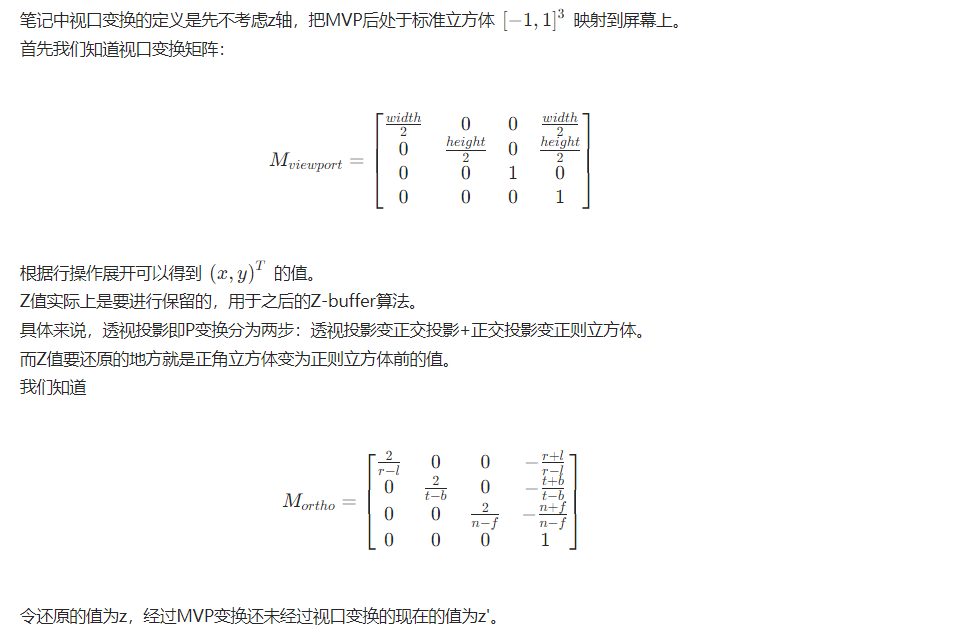
// 视口变换 得到顶点在屏幕上的坐标 即screen space
for (auto& vert : v)
{
vert.x() = 0.5 * width * (vert.x() + 1.0);
vert.y() = 0.5 * height * (vert.y() + 1.0);
// 为了Zbuffer保留Z值
// (透视)投影变换最后一步是从正交投影变换到正则立方体
// 而这一步就是把正则立方体的z值还原到正交投影时的z值,即原始z值
vert.z() = vert.z() * f1 + f2;
}
// 记录经过MVP视口变换后的顶点坐标
// 完成顶点变换,变换到屏幕空间
for (int i = 0; i < 3; ++i)
{
//screen space coordinates
newtri.setVertex(i, v[i]);
}
// 记录顶点的法向量
for (int i = 0; i < 3; ++i)
{
//view space normal
newtri.setNormal(i, n[i].head<3>());
}
// 设置颜色
newtri.setColor(0, 148, 121.0, 92.0);
newtri.setColor(1, 148, 121.0, 92.0);
newtri.setColor(2, 148, 121.0, 92.0);
// 对这个小三角形进行光栅化
// 传入viewspace_pos的坐标,光线的作用是在viewspace下的
rasterize_triangle(newtri, viewspace_pos);
}
}
概括一下:
-
顶点进行MV操作,得到viewspace中的坐标
viewspace_pos,这个坐标用于后续的光线作用。光线作用发生在视图空间。 -
顶点进行MVP+视口操作,把三维空间顶点坐标换算到二维空间即screen space上。
-
- 在其次变换中,w并未发生变换,它记录了原本的z值信息,用于后续的插值。
- 视口变换中,将(x, y)变换到二维平面,而z值变为原始z值,用于后续Z-buffer算法。透视投影变换=变换到正交投影+变换到正则立方体,即把z值逆变换回正交投影时的z值。
-
记录viewspace下的顶点法向量。因为光线作用在viewspace下。
光线作用发生在view space:
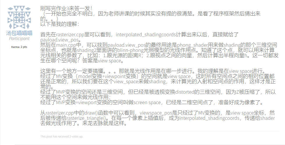
其中的难理解的变换解释如下
1.视口变换:
// 视口变换 得到顶点在屏幕上的坐标 即screen space
for (auto& vert : v)
{
	vert.x() = 0.5 * width * (vert.x() + 1.0);
	vert.y() = 0.5 * height * (vert.y() + 1.0);
	// 为了Zbuffer保留Z值
	// (透视)投影变换最后一步是从正交投影变换到正则立方体
	// 而这一步就是把正则立方体的z值还原到正交投影时的z值,即原始z值
	vert.z() = vert.z() * f1 + f2;
}
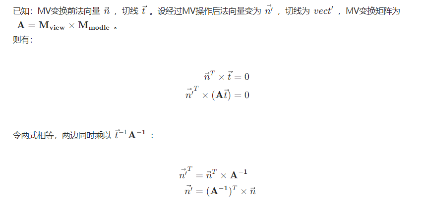
2.viewspace下的顶点法向量:
// 计算在MV转换后各顶点的法向量
// 利用原来点法向量推出MV变换后法向量
// 因为光线作用是在view_space下进行的
Eigen::Matrix4f inv_trans = (view * model).inverse().transpose();
Eigen::Vector4f n[] = {
		inv_trans * to_vec4(t->normal[0], 0.0f),
		inv_trans * to_vec4(t->normal[1], 0.0f),
		inv_trans * to_vec4(t->normal[2], 0.0f)
};
3.rasterizer_triangle函数(光栅化、片元处理、帧缓冲阶段)
void rst::rasterizer::rasterize_triangle(const Triangle& t, const std::array<Eigen::Vector3f, 3>& view_pos)
{
	auto v = t.toVector4();
	// Bouding Box
	int min_x = std::min(v[0].x(), std::min(v[1].x(), v[2].x())), min_y = std::min(v[0].y(), std::min(v[1].y(), v[2].y())), max_x = std::max(v[0].x(), std::max(v[1].x(), v[2].x())), max_y = std::max(v[0].y(), std::max(v[1].y(), v[2].y()));

	// 采样
	for (int x = min_x; x <= max_x; x++)
		for (int y = min_y; y <= max_y; y++)
		{
			if (insideTriangle(x + 0.5, y + 0.5, t.v))
			{
				// Z-Buffer算法
				// 获取当前像素的深度
				// 线性插值,透视矫正
				//    * v[i].w() is the vertex view space depth value z.
				//    * Z is interpolated view space depth for the current pixel
				//    * zp is depth between zNear and zFar, used for z-buffer
				auto tmp = computeBarycentric2D(x + 0.5, y + 0.5, t.v);
				float alpha, beta, gamma;
				std::tie(alpha, beta, gamma) = tmp;
				float Z = 1.0 / (alpha / v[0].w() + beta / v[1].w() + gamma / v[2].w());
				float zp = alpha * v[0].z() / v[0].w() + beta * v[1].z() / v[1].w() + gamma * v[2].z() / v[2].w();
				zp *= Z;
				if (zp < depth_buf[get_index(x, y)])// 当前深度更靠前
				{
					depth_buf[get_index(x, y)] = zp;
					auto interpolated_color = interpolate(alpha, beta, gamma, t.color[0], t.color[1], t.color[2], 1);
					auto interpolated_normal = interpolate(alpha, beta, gamma, t.normal[0], t.normal[1], t.normal[2], 1).normalized();
					auto interpolated_texcoords = interpolate(alpha, beta, gamma, t.tex_coords[0], t.tex_coords[1], t.tex_coords[2], 1);
					// 前面提到 光照作用是在视图坐标下的
					auto interpolated_shadingcoords = interpolate(alpha, beta, gamma, view_pos[0], view_pos[1], view_pos[2], 1);

					// 把信息存到shader参数中
					fragment_shader_payload payload(interpolated_color, interpolated_normal.normalized(), interpolated_texcoords, texture ? &*texture : nullptr);
					payload.view_pos = interpolated_shadingcoords;
					auto pixel_color = fragment_shader(payload);

					set_pixel(Vector2i(x, y), pixel_color);
				}
			}
		}
}
1.光栅化阶段:
- bouding box
- 采样,判断每个像素是否在小三角形内,如果在,进行深度测试——深度插值得到这个像素的z值与缓存进行比较。
- 通过深度测试后对三角形各个属性进行插值计算。
2.片元处理阶段:
- 把三角形插值信息传入shader参数中并调用片元处理函数
3.帧缓冲阶段:
- 把shader处理结果传到frame_buffer中(set_pixel)
此函数里调用的较为重要的几个函数
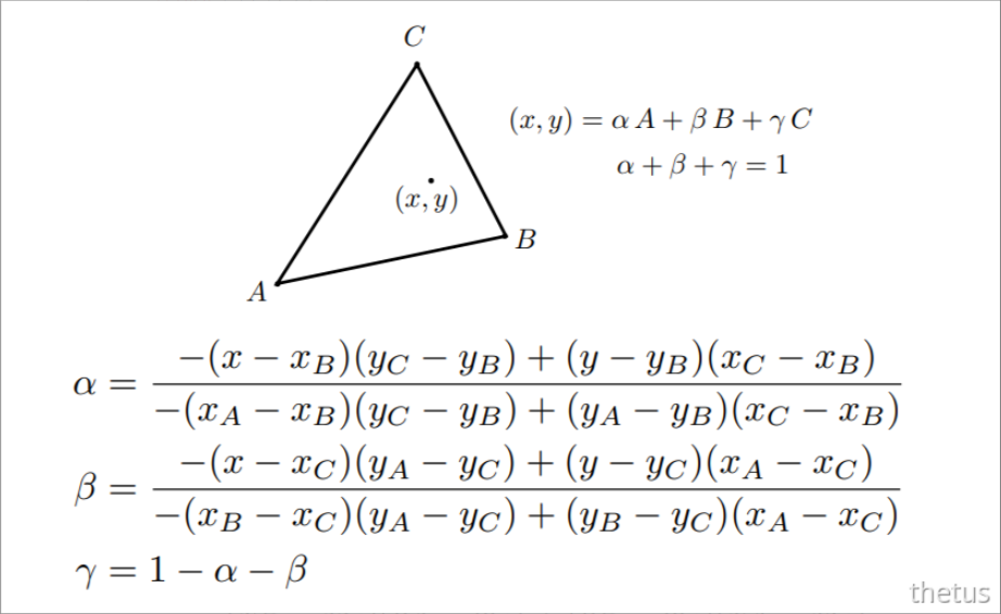
求重心坐标函数computeBarycentric2D:
static std::tuple<float, float, float> computeBarycentric2D(float x, float y, const Vector4f* v) {
	float c1 = (x * (v[1].y() - v[2].y()) + (v[2].x() - v[1].x()) * y + v[1].x() * v[2].y() - v[2].x() * v[1].y()) / (v[0].x() * (v[1].y() - v[2].y()) + (v[2].x() - v[1].x()) * v[0].y() + v[1].x() * v[2].y() - v[2].x() * v[1].y());
	float c2 = (x * (v[2].y() - v[0].y()) + (v[0].x() - v[2].x()) * y + v[2].x() * v[0].y() - v[0].x() * v[2].y()) / (v[1].x() * (v[2].y() - v[0].y()) + (v[0].x() - v[2].x()) * v[1].y() + v[2].x() * v[0].y() - v[0].x() * v[2].y());
	float c3 = (x * (v[0].y() - v[1].y()) + (v[1].x() - v[0].x()) * y + v[0].x() * v[1].y() - v[1].x() * v[0].y()) / (v[2].x() * (v[0].y() - v[1].y()) + (v[1].x() - v[0].x()) * v[2].y() + v[0].x() * v[1].y() - v[1].x() * v[0].y());
	return { c1,c2,c3 };
}
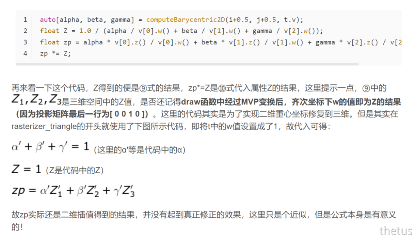
倾斜透视矫正:
                auto tmp = computeBarycentric2D(x + 0.5, y+0.5, t.v);
                float alpha, beta, gamma;
                std::tie(alpha, beta, gamma) = tmp;

                float Z = 1.0 / (alpha / v[0].w() + beta / v[1].w() + gamma / v[2].w());
                float zp = alpha * v[0].z() / v[0].w() + beta * v[1].z() / v[1].w() + gamma * v[2].z() / v[2].w();
                zp *= Z;
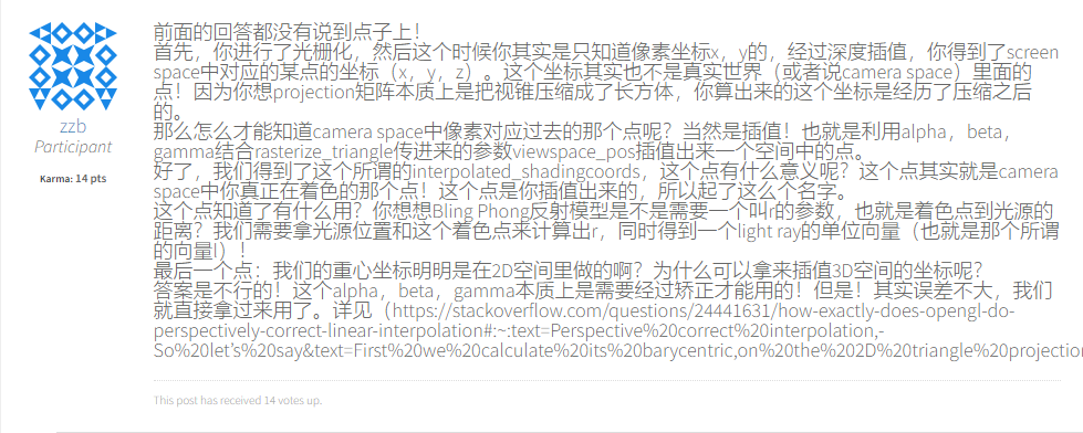
我们的重心坐标往往都是在屏幕空间下所得到的,如果直接使用屏幕空间下的重心坐标进行插值会造成一定的误差,与在view space下是不一样的。
具体解决方案:
https://zhuanlan.zhihu.com/p/144331875
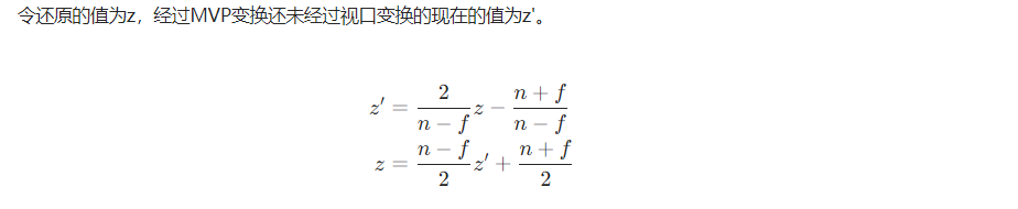
下面给出上述链接未给出的过程。(即z和zp的关系)
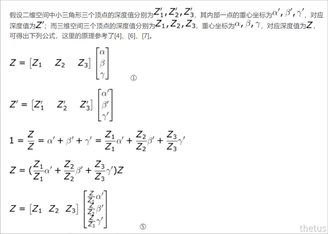
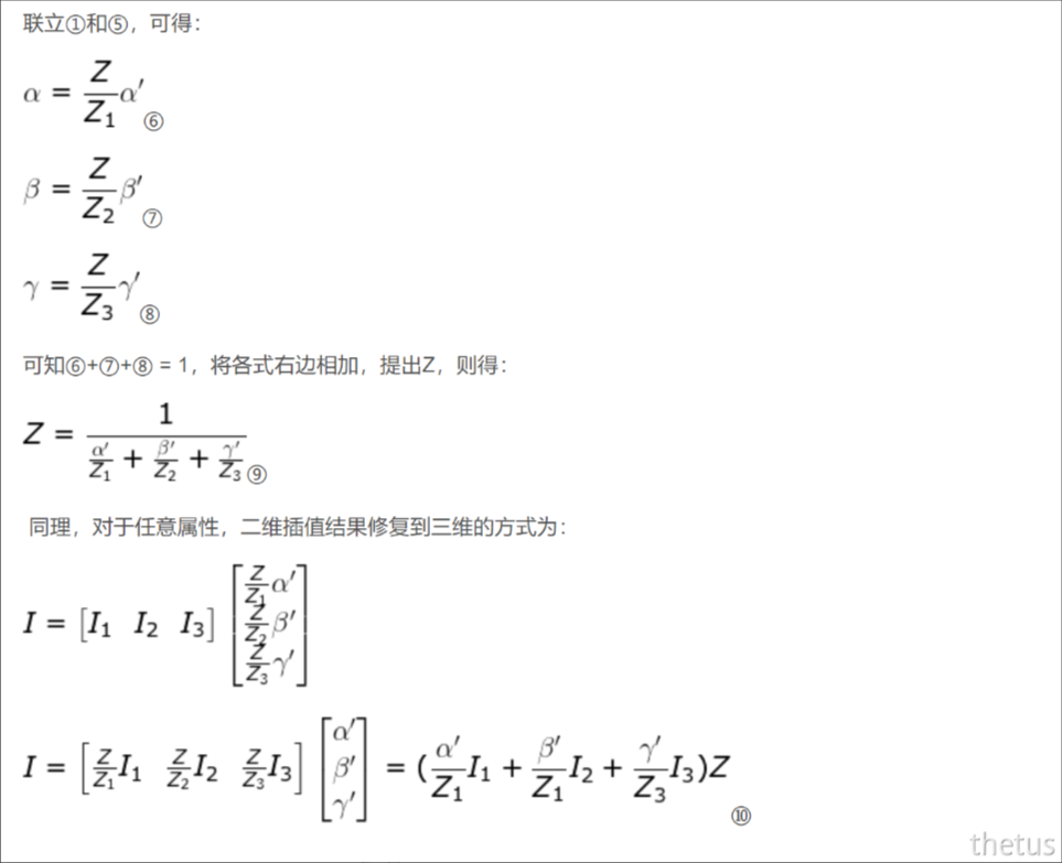
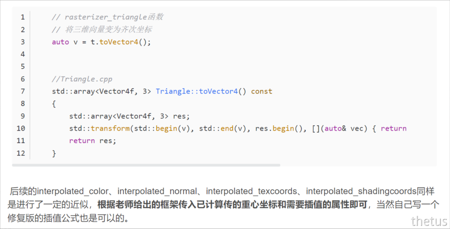
属性插值:
着色模型
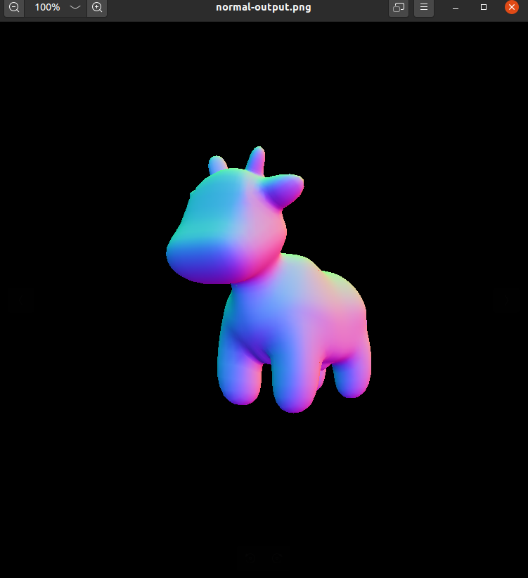
1.normal模型
// 根据法线进行不同着色
Eigen::Vector3f normal_fragment_shader(const fragment_shader_payload& payload)
{
    Eigen::Vector3f return_color = (payload.normal.head<3>().normalized() + Eigen::Vector3f(1.0f, 1.0f, 1.0f)) / 2.f;
    Eigen::Vector3f result;
    result << return_color.x() * 255, return_color.y() * 255, return_color.z() * 255;
    return result;
}
这个函数并不是光照模型,只是根据不同法线返回不同颜色值。
第一行的代码,首先取出当前待着色像素点的法向量的X,Y,Z坐标并归一化,故此时X,Y,Z都在[-1,1]之间,加上(1.0f, 1.0f, 1.0f)后,变为[0,2],再除以2,即得[0,1],再分别乘以255即可得到各个颜色值了。
normal模型渲染结果:
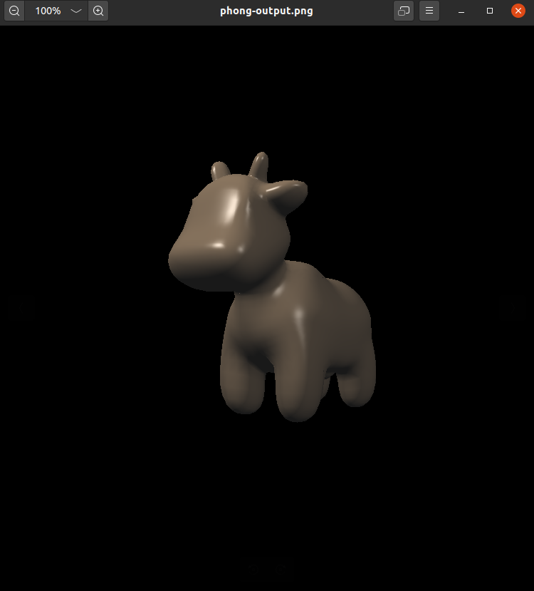
2.phong模型
Eigen::Vector3f phong_fragment_shader(const fragment_shader_payload& payload)
{
    // 泛光、漫反射、高光系数
    Eigen::Vector3f ka = Eigen::Vector3f(0.005, 0.005, 0.005);
    Eigen::Vector3f kd = payload.color;
    Eigen::Vector3f ks = Eigen::Vector3f(0.7937, 0.7937, 0.7937);

    // 灯光位置和强度
    auto l1 = light{{20, 20, 20}, {500, 500, 500}};
    auto l2 = light{{-20, 20, 0}, {500, 500, 500}};

    std::vector<light> lights = {l1, l2};// 光照
    Eigen::Vector3f amb_light_intensity{10, 10, 10};// 环境光强度
    Eigen::Vector3f eye_pos{0, 0, 10};// 相机位置

    float p = 150;

    // ping point的信息
    Eigen::Vector3f color = payload.color;
    Eigen::Vector3f point = payload.view_pos;// view space
    Eigen::Vector3f normal = payload.normal;

    Eigen::Vector3f result_color = {0, 0, 0};// 光照结果

    Eigen::Vector3f La = ka.cwiseProduct(amb_light_intensity);
    // 遍历每一束光
    for (auto& light : lights)
    {
        Eigen::Vector3f l = (light.position - point).normalized(), v = (eye_pos - point).normalized();// 光照方向和观察方向
        Eigen::Vector3f h = (l + v).normalized();// 半程向量
        Eigen::Vector3f I = light.intensity;// 光强
        float r2 = (light.position - point).dot(light.position - point);
        Eigen::Vector3f Ld = kd.cwiseProduct(I / r2) * std::max(0.0f, normal.dot(l));//cwiseProduct()函数允许Matrix直接进行点对点乘法,而不用转换至Array
        Eigen::Vector3f Ls = ks.cwiseProduct(I / r2) * std::pow(std::max(0.0f, normal.dot(h)), p);
        result_color += La + Ld + Ls;
    }
    //Eigen::Vector3f La = ka.cwiseProduct(amb_light_intensity);
    //result_color += La;
    return result_color * 255.f;
}
直接根据公式写就行,这里我认为环境光应该放在循环外,不过这样渲出来的结果相比说说明偏暗,但后面的displacement又要放在外面否则偏亮。
phong模型渲染结果:
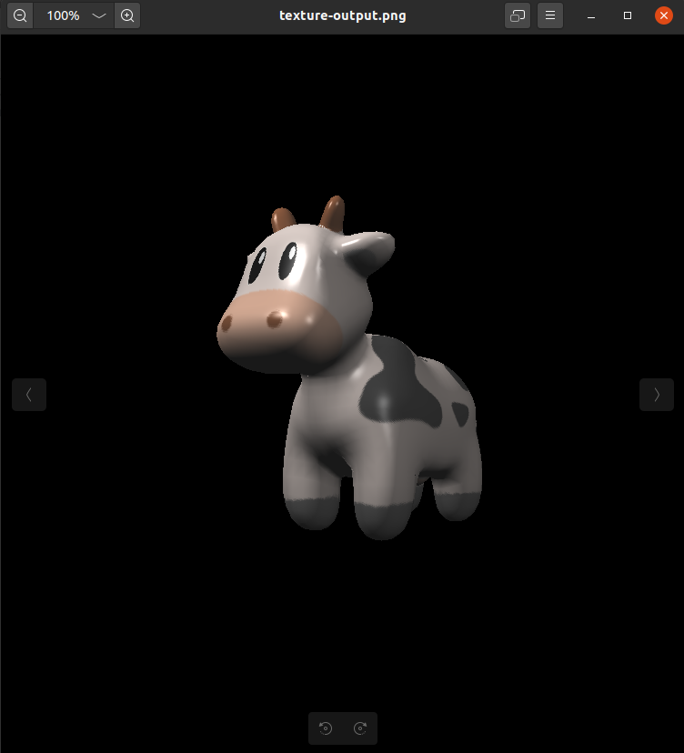
3.texture模型
Eigen::Vector3f texture_fragment_shader(const fragment_shader_payload& payload)
{
    Eigen::Vector3f return_color = {0, 0, 0};
    if (payload.texture)
    {
        return_color = payload.texture->getColor(payload.tex_coords.x(), payload.tex_coords.y());// 获取材质颜色信息
    }
    Eigen::Vector3f texture_color;
    texture_color << return_color.x(), return_color.y(), return_color.z();

    Eigen::Vector3f ka = Eigen::Vector3f(0.005, 0.005, 0.005);
    Eigen::Vector3f kd = texture_color / 255.f;// 材质颜色影响漫反射系数
    Eigen::Vector3f ks = Eigen::Vector3f(0.7937, 0.7937, 0.7937);

    auto l1 = light{{20, 20, 20}, {500, 500, 500}};
    auto l2 = light{{-20, 20, 0}, {500, 500, 500}};

    std::vector<light> lights = {l1, l2};
    Eigen::Vector3f amb_light_intensity{10, 10, 10};
    Eigen::Vector3f eye_pos{0, 0, 10};

    float p = 150;

    Eigen::Vector3f color = texture_color;
    Eigen::Vector3f point = payload.view_pos;
    Eigen::Vector3f normal = payload.normal;

    Eigen::Vector3f result_color = {0, 0, 0};

    Eigen::Vector3f La = ka.cwiseProduct(amb_light_intensity);
    for (auto& light : lights)
    {
        Eigen::Vector3f l = (light.position - point).normalized(), v = (eye_pos - point).normalized();// 光照方向和观察方向
        Eigen::Vector3f h = (l + v).normalized();// 半程向量
        Eigen::Vector3f I = light.intensity;// 光强
        float r2 = (light.position - point).dot(light.position - point);
        Eigen::Vector3f Ld = kd.cwiseProduct(I / r2) * std::max(0.0f, normal.dot(l));//cwiseProduct()函数允许Matrix直接进行点对点乘法,而不用转换至Array
        Eigen::Vector3f Ls = ks.cwiseProduct(I / r2) * std::pow(std::max(0.0f, normal.dot(h)), p);
        result_color += La + Ld + Ls;
    }
    // Eigen::Vector3f La = ka.cwiseProduct(amb_light_intensity);
    // result_color += La;
    return result_color * 255.f;
}
只需要理解纹理影响颜色,颜色影响漫反射系数。所以在一开始读取材质纹理的颜色信息,再传给漫反射系数,之后再套用phong模型即可。
这里框架有一个问题,就是在getColor中,没有限制UV坐标的范围,加上即可。
Eigen::Vector3f getColor(float u, float v)
{
	// 限制(u, v)坐标范围
	u = std::fmin(1, std::fmax(u, 0));
	v = std::fmin(1, std::fmax(v, 0));

	auto u_img = u * width;
	auto v_img = (1 - v) * height;
	auto color = image_data.at<cv::Vec3b>(v_img, u_img);// 四舍五入
	return Eigen::Vector3f(color[0], color[1], color[2]);
}
这样做后,编译会显示一个报错,不过并不影响结果。
texture模型渲染结果:
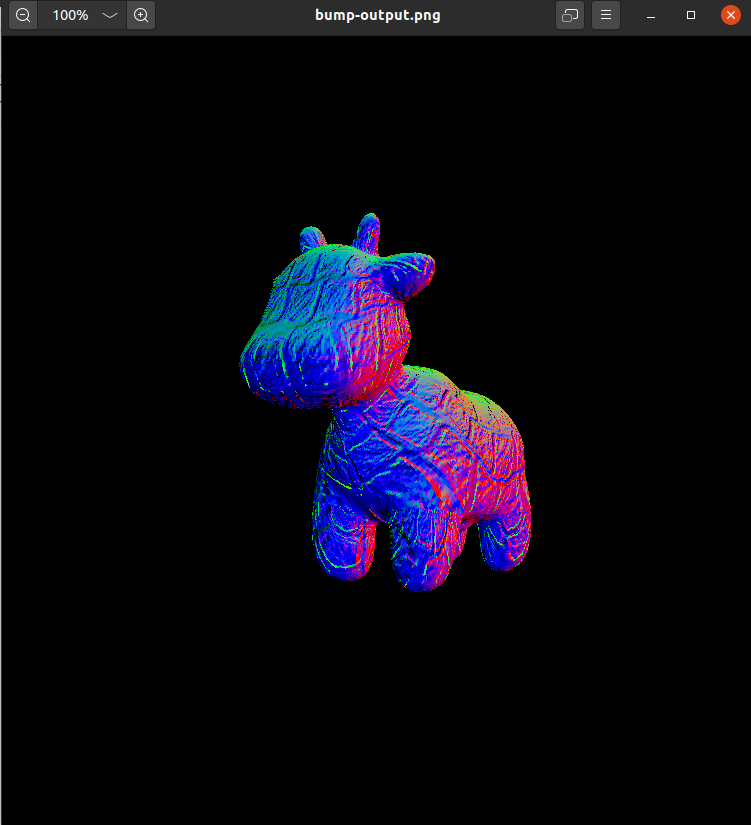
4.bump和displacement模型
这一部分助教在论坛说会在光线追踪部分详细介绍,现在按照注释实现即可。
所以原理我目前也不是完全明白…
Eigen::Vector3f bump_fragment_shader(const fragment_shader_payload& payload)
{

    Eigen::Vector3f ka = Eigen::Vector3f(0.005, 0.005, 0.005);
    Eigen::Vector3f kd = payload.color;
    Eigen::Vector3f ks = Eigen::Vector3f(0.7937, 0.7937, 0.7937);

    auto l1 = light{ {20, 20, 20}, {500, 500, 500} };
    auto l2 = light{ {-20, 20, 0}, {500, 500, 500} };

    std::vector<light> lights = { l1, l2 };
    Eigen::Vector3f amb_light_intensity{ 10, 10, 10 };
    Eigen::Vector3f eye_pos{ 0, 0, 10 };

    float p = 150;

    Eigen::Vector3f color = payload.color;
    Eigen::Vector3f point = payload.view_pos;
    Eigen::Vector3f normal = payload.normal;


    float kh = 0.2, kn = 0.1;

    // TODO: Implement bump mapping here
    // Let n = normal = (x, y, z)
    // Vector t = (x*y/sqrt(x*x+z*z),sqrt(x*x+z*z),z*y/sqrt(x*x+z*z))
    // Vector b = n cross product t
    // Matrix TBN = [t b n]

    float x = normal.x();
    float y = normal.y();
    float z = normal.z();
    Eigen::Vector3f t{ x * y / std::sqrt(x * x + z * z), std::sqrt(x * x + z * z), z * y / std::sqrt(x * x + z * z) };
    Eigen::Vector3f b = normal.cross(t);
    Eigen::Matrix3f TBN;
    TBN << t.x(), b.x(), normal.x(),
        t.y(), b.y(), normal.y(),
        t.z(), b.z(), normal.z();

    // dU = kh * kn * (h(u+1/w,v)-h(u,v))
    // dV = kh * kn * (h(u,v+1/h)-h(u,v))
    // Vector ln = (-dU, -dV, 1)
    // Normal n = normalize(TBN * ln)

    float u = payload.tex_coords.x(), v = payload.tex_coords.y();
    float w = payload.texture->width, h = payload.texture->height;

    float dU = kh * kn * (payload.texture->getColor(u + 1.0f / w, v).norm() - payload.texture->getColor(u, v).norm());
    float dV = kh * kn * (payload.texture->getColor(u, v + 1.0f / h).norm() - payload.texture->getColor(u, v).norm());

    Eigen::Vector3f ln{ -dU,-dV,1.0f };

    normal = TBN * ln;
    // 归一化
    Eigen::Vector3f result_color = normal.normalized();
    return result_color * 255.f;
}
bump模型渲染结果:
Eigen::Vector3f displacement_fragment_shader(const fragment_shader_payload& payload)
{

    Eigen::Vector3f ka = Eigen::Vector3f(0.005, 0.005, 0.005);
    Eigen::Vector3f kd = payload.color;
    Eigen::Vector3f ks = Eigen::Vector3f(0.7937, 0.7937, 0.7937);

    auto l1 = light{ {20, 20, 20}, {500, 500, 500} };
    auto l2 = light{ {-20, 20, 0}, {500, 500, 500} };

    std::vector<light> lights = { l1, l2 };
    Eigen::Vector3f amb_light_intensity{ 10, 10, 10 };
    Eigen::Vector3f eye_pos{ 0, 0, 10 };

    float p = 150;

    Eigen::Vector3f color = payload.color;
    Eigen::Vector3f point = payload.view_pos;
    Eigen::Vector3f normal = payload.normal;

    float kh = 0.2, kn = 0.1;

    float x = normal.x();
    float y = normal.y();
    float z = normal.z();
    Eigen::Vector3f t{ x * y / std::sqrt(x * x + z * z), std::sqrt(x * x + z * z), z * y / std::sqrt(x * x + z * z) };
    Eigen::Vector3f b = normal.cross(t);
    Eigen::Matrix3f TBN;
    TBN << t.x(), b.x(), normal.x(),
        t.y(), b.y(), normal.y(),
        t.z(), b.z(), normal.z();

    float u = payload.tex_coords.x(), v = payload.tex_coords.y();
    float w = payload.texture->width, h = payload.texture->height;

    float dU = kh * kn * (payload.texture->getColor(u + 1 / w, v).norm() - payload.texture->getColor(u, v).norm());
    float dV = kh * kn * (payload.texture->getColor(u, v + 1 / h).norm() - payload.texture->getColor(u, v).norm());

    Eigen::Vector3f ln{ -dU, -dV, 1 };
    //与凹凸贴图的区别就在于这句话
    point += (kn * normal * payload.texture->getColor(u, v).norm());
    normal = (TBN * ln).normalized();
    Eigen::Vector3f result_color = { 0, 0, 0 };

    for (auto& light : lights)
    {
        Eigen::Vector3f l = (light.position - point).normalized(), v = (eye_pos - point).normalized();// 光照方向和观察方向
        Eigen::Vector3f h = (l + v).normalized();// 半程向量
        Eigen::Vector3f I = light.intensity;// 光强
        float r2 = (light.position - point).dot(light.position - point);
        Eigen::Vector3f Ld = kd.cwiseProduct(I / r2) * std::max(0.0f, normal.dot(l));//cwiseProduct()函数允许Matrix直接进行点对点乘法,而不用转换至Array
        Eigen::Vector3f Ls = ks.cwiseProduct(I / r2) * std::pow(std::max(0.0f, normal.dot(h)), p);
        result_color += Ld + Ls;
    }

    return result_color * 255.f;
}
这里也存在我上面说的问题,即环境光的位置。
如果把环境光放在循环里面,渲染出来偏浅。
放在外面和说明基本一致,但还是有些偏暗。
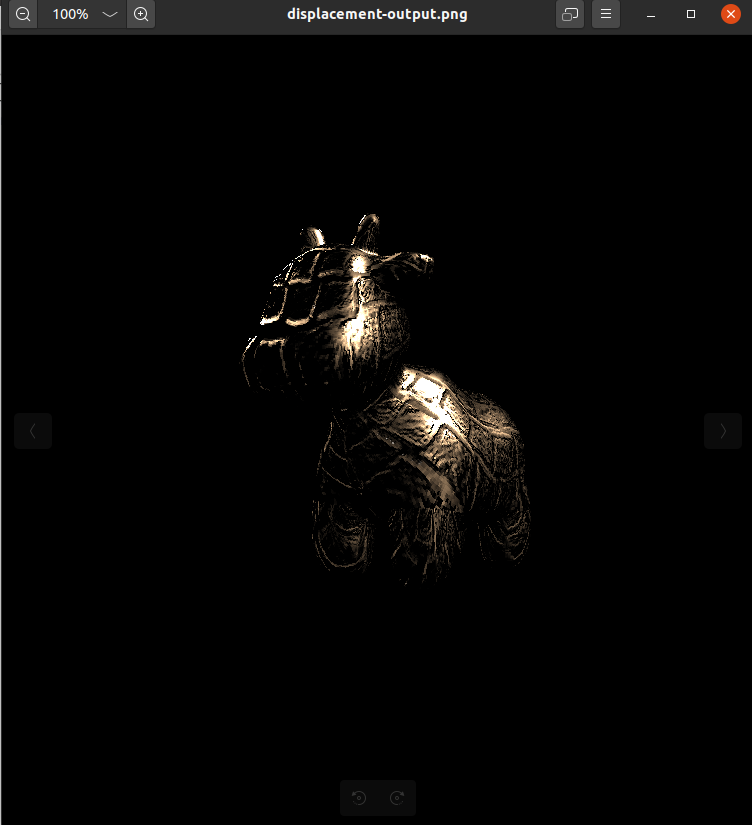
displacement模型渲染结果:
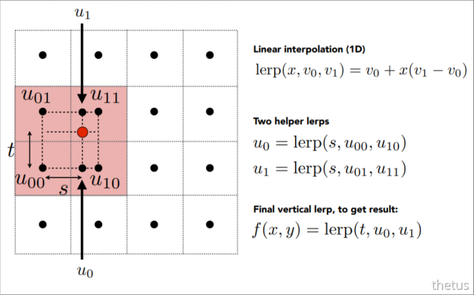
双线性插值
Eigen::Vector3f getColorBilinear(float u, float v)
{
	// 限制(u, v)坐标范围
	u = std::fmin(1, std::fmax(u, 0));
	v = std::fmin(1, std::fmax(v, 0));

	auto u_img = u * width, v_img = (1 - v) * width;
	float u0 = std::fmax(1, floor(u_img - 0.5)), u1 = floor(u_img + 0.5);
	float v0 = std::fmax(1, floor(v_img - 0.5)), v1 = floor(v_img + 0.5);
	float s = (u_img - u0) / (u1 - u0), t = (v_img - v0) / (v1 - v0);
	auto c00 = image_data.at<cv::Vec3b>(v0, u0);
	auto c01 = image_data.at<cv::Vec3b>(v0, u1);
	auto c10 = image_data.at<cv::Vec3b>(v1, u0);
	auto c11 = image_data.at<cv::Vec3b>(v1, u1);
	auto c0 = c00 + s * (c01 - c00);
	auto c1 = c10 + s * (c11 - c10);
	auto color = c0 + t * (c1 - c0);
   // std::cout << color << std::endl;
	return Eigen::Vector3f(color[0], color[1], color[2]);
}
这里放一个双线性插值后的效果对比,不过我不知道怎样缩小纹理图大小,我缩小后使用双线性插值牛牛鼻子旁边会出现鼻涕一样的颜色… 所以就用的原贴图来进行对比。
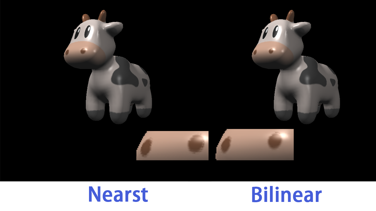
鼻子边缘还是能看出效果的,不过效果不太明显就是了。


 1667
1667

 被折叠的 条评论
为什么被折叠?
被折叠的 条评论
为什么被折叠?
 到【灌水乐园】发言


