


- Apollo项目的源码可以从github上获取:ApolloAuto/apollo。
- 本文中贴出的源码取自2019年2月7日的版本(版本:3.5)
概述
什么是参考线
- 就是高精地图所提供的道路的中心线,在此基础上做平滑得到的一条线。
- 它是理想状态下没有障碍物的一条线。要保障平滑,所以在运动的时候,汽车不会横向摆动

- 参考线可以简单理解为候选路径
导航规划的路线
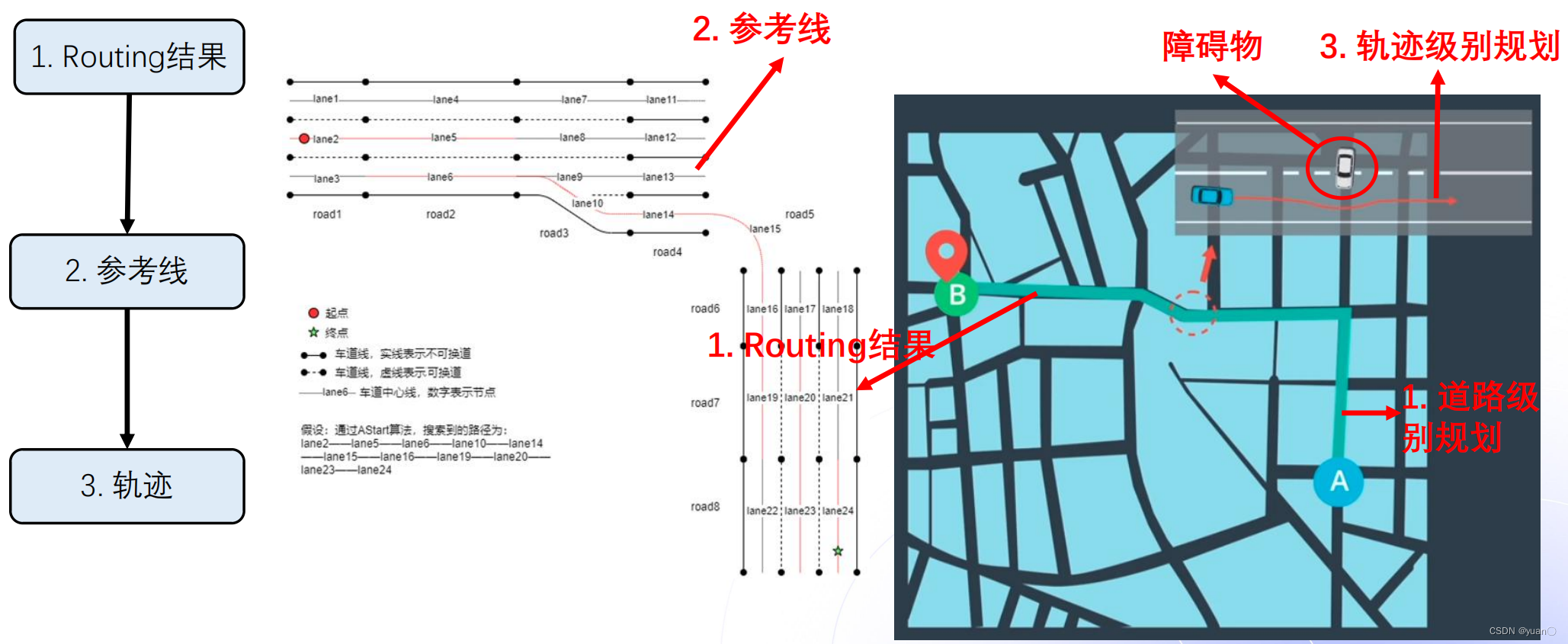
导航规划的路线一般由三个部分组成:Routing、参考线以及轨迹。
- Routing: 全局路径规划的结果,一般规划出来的长度为几十公里甚至上百公里,若没有障碍物,车辆将会沿着这条路径一直行驶。若有障碍物,则会由Planning模块发布回Routing模块进行重新规划。
- 参考线: 决策规划模块根据车辆的实时位置进行计算。参考线的计算依赖于Routing的结果,但同时需要车辆周围的动态信息(障碍物、交通规则)。参考线相当于Routing结果里局部数据(车辆当前位置的一段Routing),距离通常只有几百米。参考线可能会有多条。
- 轨迹: 是规划决策模块的最终输出结果。轨迹的输入是参考线。轨迹不仅包含车辆的路径信息,也包括车辆的动态信息(速度、加速度等)。
为什么需要参考线
参考线是根据routing规划的路线,生成一系列参考轨迹,提供给规划算法作为参考,从而生成最终的规划轨迹。
为什么要提供参考呢?因为道路是结构化道路,在没有参考的情况下,需要通过搜索算法来查找路线,这种场景在机器人路径规划中比较普遍,机器人在一个开放空间只要没有障碍物它就可以行走,而车不一样,车是在道路上行驶的,在提供参考的情况下,节省了查找的时间和复杂度,降低了算法的难度,这也就是参考线的意义。
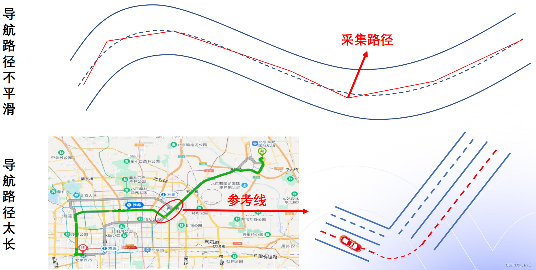
为什么不直接使用routing?
- 导航路径不平滑
- 导航路径太长
这会带来什么后果
-
不平滑可能导致车辆形式不平稳
-
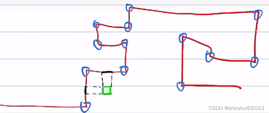
过长的导航路线:
- 不利于坐标转换:路径越长,离散的点越多,又需要遍历点找到距离最短的点:匹配点,才能计算(s,l)坐标系下的s,这个计算量就很大
- 过长的路径,障碍物的投影可能不唯一:如图绿色
- 导航路径一般不是平滑的路线,不利于后面的控制
解决方法:在全局路径上截取一小段路径做平滑,平滑后的线就是参考线(参考线就是s轴要做投影的)
参考线是解决方案,解决导航路径过长,不平滑的问题
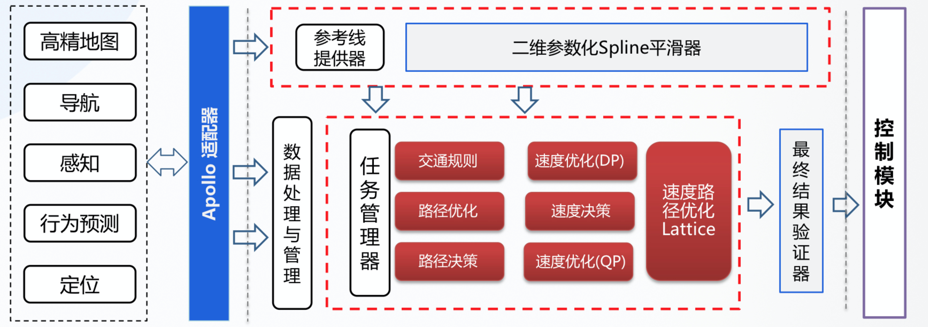
参考线在整个Planning模块中所处的位置

决策规划模块负责生成车辆的行驶轨迹。要做到这一点,决策规划模块需要从宏观到局部经过三个层次来进行决策。
-
第一个层次是Routing的搜索结果。Routing模块的输入是若干个按顺序需要达到的途经点(也可能只有一个起点和一个终点)。Routing模块根据地图的拓扑结构搜索出可达的完整路径来,这个路线的长度可能是几公里甚至几百公里。因此这个是最为宏观的数据。另外,Routing的搜索结果是相对固定的。在没有障碍物的情况下,车辆会一直沿着原先获取到的Routing路线行驶。只有当车辆行驶出了原先规划的路线之外(例如:为了避障),才会重新发送请求给Routing模块,以重新计算路线。
-
第二个层次就是参考线。决策规划魔抗会实时根据车辆的具体位置来计算参考线。参考线的计算会以Routing的路线为基础。但同时,参考线会考虑车辆周围的动态信息。比如:障碍物,交通规则灯。参考线是包含车辆所在位置周边一定的范围,通常是几百米的长度。相较于Routing结果,它是较为局部的数据。
-
第三个层次是轨迹。轨迹是决策规划魔抗的最终输出结果。它的依据是参考线。在同一时刻,参考线可能会有多条。比如:在变道的时候,自车所在车道和目标车道都会有一条参考线。而轨迹,是在所有可能的结果中,综合决策和优化的结果,最终的唯一结果。因此它是更为具体和局部的数据。轨迹不仅仅包含了车辆的路线,还包含了车辆行驶这条路线时的详细状态。例如:车辆的方向,速度,加速度等等。
ReferenceLine 是整个规划算法的基础,在apollo中起到了关键的承上启下的作用。,规划的目的就是使车辆按照ReferenceLine行驶。
-
参考线是根据车辆位置相对局部的一个数据,它包含了车辆前后一定范围内的路径信息。在车辆行驶过程中,Planning会在每一个计算周期中生成ReferenceLine。
-
然后在这个ReferenceLine上进行后面的处理。例如:交通规则逻辑,障碍物投影,路径优化,速度决策等等。可以说,参考线贯穿了整个Planning模块的实现。
关系
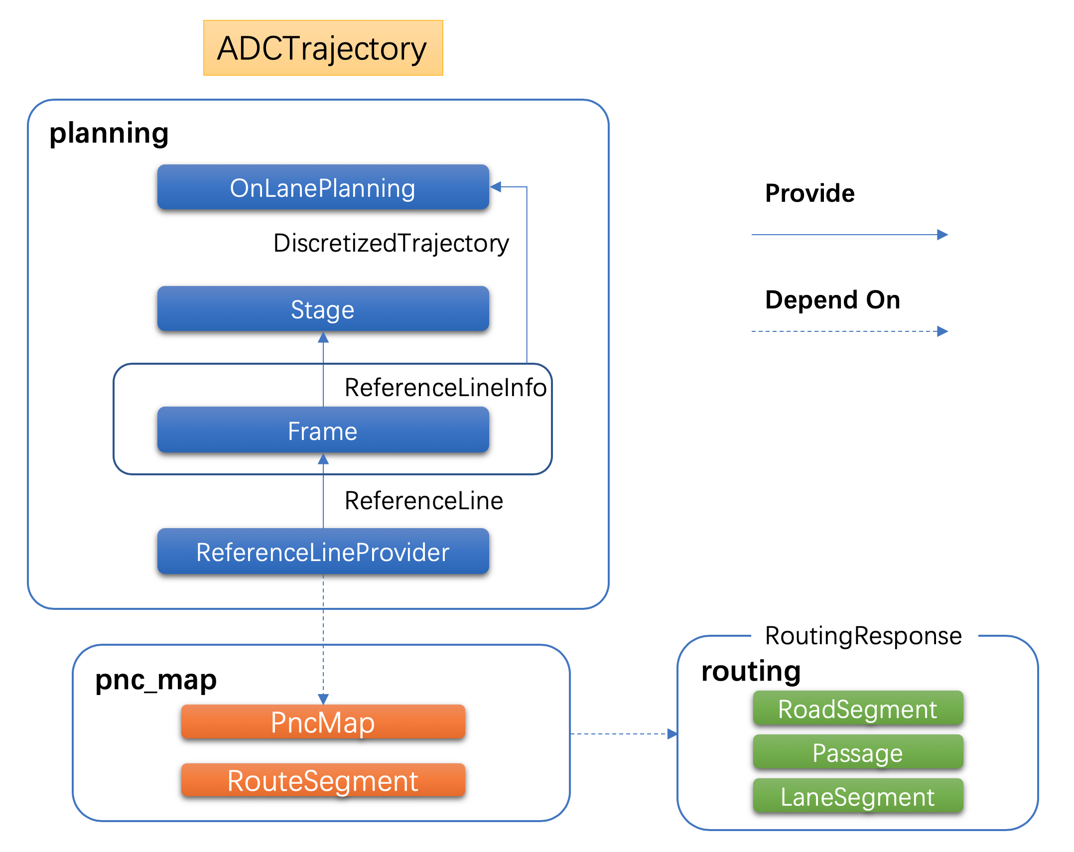
从这幅图中可以看出,这里涉及到三个模块:
- routing模块:生成全局路径规划
- pnc map模块:负责读取和处理routing搜索结果
- planning模块:根据routing结果和车辆实时状态(包括周边环境)生成参考线和轨迹
在Planning模块中有以下三个数据结构将是本文关注的重点:
- ReferenceLine:
- 原始参考线,源码位于planning/reference_line/目录下。
- 根据Routing的搜索结果生成。
- ReferenceLineInfo:
- 源码位于planning/common/目录下。
- 参考线信息,在参考线的基础添加了决策信息,ST图等。Planning实现中,逻辑计算的基础数据结构,很多操作都会在这个数据结构上进行(例如:交通规则逻辑,障碍物投影,路径优化,速度决策等)。
- ReferenceLine和ReferenceLineInfo的关系?可以建立理解为ReferenceLine提供的是轨迹信息,而ReferenceLineInfo在ReferenceLine的基础上新添加了决策信息。
- Trajectory:下文中我们将看到,有好几个结构用来描述轨迹。它们在不同的场合下使用。这其中,ADCTrajectory是Planning模块的输出。它是Planning模块一次计算循环中,处理了所有逻辑的最终结果,包含了车辆行驶需要的所有信息。因此,这个数据将直接影响到自动驾驶车辆的行车行为。
数据结构
平滑器(ReferenceLineSmoother)
为什么需要做平滑
- 直接通过RouteSegments生成的ReferenceLine可能是不平滑的。
- 如果直接让车辆沿着不平滑的路线行驶可能造成车辆方向的抖动或者大幅变化,这对乘坐体验来说非常不好。因此,原始的路线数据需要经过算法的平滑。
一共有几种平滑器
具体的逻辑由下面这个方法完成:
/ modules/planning/reference_line/reference_line_provider.cc

bool ReferenceLineProvider::SmoothReferenceLine(
    const ReferenceLine &raw_reference_line, ReferenceLine *reference_line) {
  if (!FLAGS_enable_smooth_reference_line) {
    *reference_line = raw_reference_line;
    return true;
  }
  // generate anchor points:
  std::vector<AnchorPoint> anchor_points;
  GetAnchorPoints(raw_reference_line, &anchor_points);
  smoother_->SetAnchorPoints(anchor_points);
  if (!smoother_->Smooth(raw_reference_line, reference_line)) {
    AERROR << "Failed to smooth reference line with anchor points";
    return false;
  }
  if (!IsReferenceLineSmoothValid(raw_reference_line, *reference_line)) {
    AERROR << "The smoothed reference line error is too large";
    return false;
  }
  return true;
}
很显然,smoother_->Smooth才是平滑算法的实现。
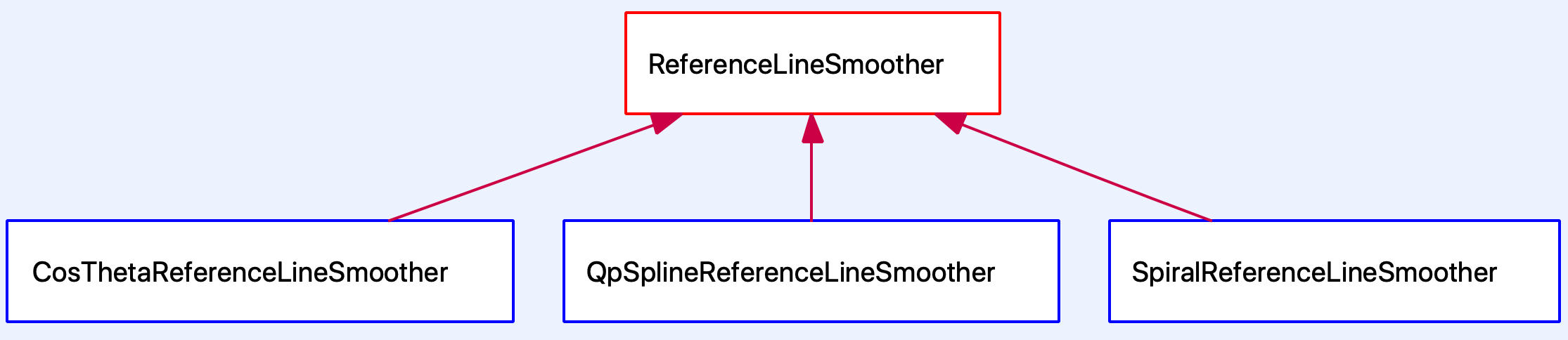
目前Apollo的Planning模块中内置了三个ReferenceLine平滑器,它们的结构如下(这是策略设计模式的应用):
- DiscretePointsReferenceLineSmoother
- QpSplineReferenceLineSmoother
- SpiralReferenceLineSmoother
它们都继承至ReferenceLineSmoother,需要提供设置锚点SetAnchorPoints和Smooth2个接口。
struct AnchorPoint {
  common::PathPoint path_point;
  double lateral_bound = 0.0;
  double longitudinal_bound = 0.0;
  // enforce smoother to strictly follow this reference point
  bool enforced = false;
};

class ReferenceLineSmoother {
 public:
  explicit ReferenceLineSmoother(const ReferenceLineSmootherConfig& config)
      : config_(config) {}

  // 虚函数,设置锚点
  virtual void SetAnchorPoints(
      const std::vector<AnchorPoint>& achor_points) = 0;

  // 虚函数,平滑参考线
  virtual bool Smooth(const ReferenceLine&, ReferenceLine* const) = 0;

  virtual ~ReferenceLineSmoother() = default;
 protected:
  ReferenceLineSmootherConfig config_;
};
常见的参考线平滑方式有:离散点的平滑(Apollo采用)、螺旋线的平滑以及样条曲线的平滑。
在实现中,Smoother用到了下面两个开源库:
- Ipopt Project
- Eigen
具体使用哪一个平滑器
具体使用哪一个平滑器由ReferenceLineProvider在初始化的时候读取配置文件来决定:
CHECK(common::util::GetProtoFromFile(FLAGS_smoother_config_filename,
                                     &smoother_config_))
  << "Failed to load smoother config file "
  << FLAGS_smoother_config_filename;
if (smoother_config_.has_qp_spline()) {
  smoother_.reset(new QpSplineReferenceLineSmoother(smoother_config_));
} else if (smoother_config_.has_spiral()) {
  smoother_.reset(new SpiralReferenceLineSmoother(smoother_config_));
} else if (smoother_config_.has_cos_theta()) {
  smoother_.reset(new CosThetaReferenceLineSmoother(smoother_config_));
} else {
  CHECK(false) << "unknown smoother config "
               << smoother_config_.DebugString();
}
目前,smoother_config_filename配置的值是/apollo/modules/planning/conf/qp_spline_smoother_config.pb.txt。因此,使用的是QpSplineReferenceLineSmoother。
DEFINE_string(smoother_config_filename,
              "/apollo/modules/planning/conf/qp_spline_smoother_config.pb.txt",
              "The configuration file for qp_spline smoother");
ReferenceLineSmoother算法
参考线平滑器使用了二次规划(Quadratic programming )和样条插值(Spline interpolation)算法。
todo
ReferenceLine生成
在每一次计算循环中,Planning模块都会通过ReferenceLineProvider生成ReferenceLine。
- ReferenceLine由Routing的搜索结果决定。
- Routing是预先搜索出的全局可达路径,而ReferenceLine是车辆当前位置的前后一段范围。
- 直行的情况下,ReferenceLine是一个。而在需要变道的时候,会有多个ReferenceLine。
我们从Apollo中Planning模块的入口说起,调用流程大致为: 
其中,箭头代表函数间的调用关系。
- Planning模块入口为PlanningComponent::Init(…)
- 它调用了OnLanePlanning::Init(…)
- 而后调用ReferenceLineProvider中的函数开启新的线程来生成ReferenceLine,其刷新的频率为20Hz。
参考线的处理主要涉及两个线程:一个是参考线生成线程,另一个是规划线程。参考线生成线程生成参考线给规划线程去规划出一条轨迹。
对于参考线生成线程,是这样的过程:
- 先调用ReferenceLineProvider::GenerateThread
- 在ReferenceLineProvider::GenerateThread中会以50hz的频率调用CreateReferenceLine创建参考线,再然后用UpdateReferenceLine更新参考线
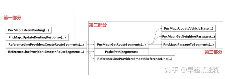
对于ReferenceLineProvider::CreateReferenceLine。更加详细一点,可以分为三部分:
- 第一部分:路由响应的处理。 PncMap::UpdateRoutingResponse
- 第二部分:根据车辆当前位置生成短期通道。这一部分主要涉及到的函数为ReferenceLineProvider::CreateRouteSegments(…)调用的PncMap::GetRouteSegments(…)。比如下图的两个灰色的RouteSegments。其生成的RouteSegments就可以用来做参考线了
- 第三部分:初始化path。
- 这一部分涉及到ReferenceLineProvider::SmoothRouteSegment函数,该函数输入为RouteSegments(上图中灰色区域),输出为ReferenceLine。
- 即对RouteSegments平滑后就是ReferenceLine。常见的参考线平滑方式有:离散点的平滑(Apollo采用)、螺旋线的平滑以及样条曲线的平滑。

而参考线生成之后就可以被规划线程调用了

轨迹结构
TrajectoryPoint仅仅是一个点。而一条轨迹一定是由许多个点构成的。因此,描述轨迹的类DiscretizedTrajectory继承自std::vector< common::TrajectoryPoint>。如下所示:
class DiscretizedTrajectory : public std::vector<common::TrajectoryPoint>
DiscretizedTrajectory还有一个子类PublishableTrajectory,它们的类结构如下图所示:

PublishableTrajectory相较于DiscretizedTrajectory来说,最主要的提供了下面这个方法:`
explicit PublishableTrajectory(const ADCTrajectory& trajectory_pb);
这个方法是将Planning模块中的轨迹数据结构导出到可发布的状态。这里的ADCTrajectory是Planning最终往外发出的数据结构,它也是在modules/planning/proto/planning.proto文件中定义的。
生成轨迹
从参考线到生成轨迹是由ReferenceLineInfo::CombinePathAndSpeedProfile方法完成的。
在EM Planner中,路径和速度是分开优化的,这里是在将这两个优化的结果(记录在ReferenceLineInfo的path_data_和speed_data_中)合并成最终的结果。
bool ReferenceLineInfo::CombinePathAndSpeedProfile(
    const double relative_time, const double start_s,
    DiscretizedTrajectory* ptr_discretized_trajectory) {
  ...

  for (double cur_rel_time = 0.0; cur_rel_time < speed_data_.TotalTime();
       cur_rel_time += (cur_rel_time < kDenseTimeSec ? kDenseTimeResoltuion
                                                     : kSparseTimeResolution)) { ①
    common::SpeedPoint speed_point;
    if (!speed_data_.EvaluateByTime(cur_rel_time, &speed_point)) {
      AERROR << "Fail to get speed point with relative time " << cur_rel_time;
      return false;
    }

    if (speed_point.s() > path_data_.discretized_path().Length()) {
      break;
    }
    common::PathPoint path_point;
    if (!path_data_.GetPathPointWithPathS(speed_point.s(), &path_point)) { ②
      AERROR << "Fail to get path data with s " << speed_point.s()
             << "path total length " << path_data_.discretized_path().Length();
      return false;
    }
    path_point.set_s(path_point.s() + start_s);

    common::TrajectoryPoint trajectory_point; ③
    trajectory_point.mutable_path_point()->CopyFrom(path_point);
    trajectory_point.set_v(speed_point.v());
    trajectory_point.set_a(speed_point.a());
    trajectory_point.set_relative_time(speed_point.t() + relative_time);
    ptr_discretized_trajectory->AppendTrajectoryPoint(trajectory_point); ④
  }
  return true;
}
这段代码中的四个点说明如下:
- 根据speed_data_中记录的总时间和间隔以确定需要在轨迹中添加多少个点。
- 根据path_data_中的数据获取相应的点以确定轨迹点的位置。
- 创建一个轨迹点TrajectoryPoint并设置位置和速度,加速度和相对时间等信息。
- 在轨迹中添加一个轨迹点。
有了轨迹之后,便可以发出供车辆行驶了。相关代码如下:
Status OnLanePlanning::Plan(
    const double current_time_stamp,
    const std::vector<TrajectoryPoint>& stitching_trajectory,
    ADCTrajectory* const trajectory_pb) {
  ...
  auto status = planner_->Plan(stitching_trajectory.back(), frame_.get());  ①

  ptr_debug->mutable_planning_data()->set_front_clear_distance(
      EgoInfo::Instance()->front_clear_distance());

  const auto* best_ref_info = frame_->FindDriveReferenceLineInfo();  ②
  ...
  trajectory_pb->mutable_latency_stats()->MergeFrom(
      best_ref_info->latency_stats());
  // set right of way status
  trajectory_pb->set_right_of_way_status(best_ref_info->GetRightOfWayStatus());
  for (const auto& id : best_ref_info->TargetLaneId()) {
    trajectory_pb->add_lane_id()->CopyFrom(id); ③
  }

  trajectory_pb->set_trajectory_type(best_ref_info->trajectory_type());

  if (FLAGS_enable_rss_info) {
    trajectory_pb->mutable_rss_info()->CopyFrom(best_ref_info->rss_info());
  }

  best_ref_info->ExportDecision(trajectory_pb->mutable_decision());

  ...
  last_publishable_trajectory_.reset(new PublishableTrajectory(
      current_time_stamp, best_ref_info->trajectory())); ④
  ...

  if (FLAGS_enable_stitch_last_trajectory) {
    last_publishable_trajectory_->PrependTrajectoryPoints(
        std::vector<TrajectoryPoint>(stitching_trajectory.begin(),
                                     stitching_trajectory.end() - 1));
  }

  last_publishable_trajectory_->PopulateTrajectoryProtobuf(trajectory_pb); ⑤

  best_ref_info->ExportEngageAdvice(trajectory_pb->mutable_engage_advice());

  return status;
}
这段代码中的几个点说明如下:
- planner_->Plan是执行每个Planner的主体算法逻辑。
- 在有多个ReferenceLineInfo的情况下,选取最合适的一条。
- 记录ReferenceLineInfo包含的lane id。
- 将轨迹的数据格式转换成PublishableTrajectory类型并记录到last_publishable_trajectory_中。
- 导出成最终格式:ADCTrajectory。Apollo 3.5已经改用新的框架Cyber RT,最终轨迹的发出是在Cyber Component的实现PlanningComponent发出。相关代码如下:
 ADCTrajectory adc_trajectory_pb;
  planning_base_->RunOnce(local_view_, &adc_trajectory_pb);
  auto start_time = adc_trajectory_pb.header().timestamp_sec();
  common::util::FillHeader(node_->Name(), &adc_trajectory_pb);

  // modify trajectory relative time due to the timestamp change in header
  const double dt = start_time - adc_trajectory_pb.header().timestamp_sec();
  for (auto& p : *adc_trajectory_pb.mutable_trajectory_point()) {
    p.set_relative_time(p.relative_time() + dt);
  }
  planning_writer_->Write(std::make_shared<ADCTrajectory>(adc_trajectory_pb));
至此,决策规划模块的任务就完成了。接下来就是由控制模块按照这里发出的轨迹来控制车辆的行驶。
参考
- apollo介绍之参考线(二十七)
- 万字讲解Apollo,全网Apollo资料整理和学习
- Apollo Planning模块源代码分析
- apollo介绍之参考线(二十七):没有看完,有点吃力
- Apollo星火计划学习笔记——参考线平滑算法解析及实现(以U型弯道场景仿真调试为例)
在车辆行驶过程中,必不可少的就是判断自车以及障碍物所处的位置。这就很自然的需要将物体投影到参考线上来进行计算。对于这些内容,可以浏览下面这些接口的实现。这些逻辑基本上是点和位置的计算,这里就不展开了。
ReferencePoint GetReferencePoint(const double s) const;
common::FrenetFramePoint GetFrenetPoint(
  const common::PathPoint& path_point) const;
std::vector<ReferencePoint> GetReferencePoints(double start_s,
                                             double end_s) const;
size_t GetNearestReferenceIndex(const double s) const;
ReferencePoint GetNearestReferencePoint(const common::math::Vec2d& xy) const;
std::vector<hdmap::LaneSegment> GetLaneSegments(const double start_s,
                                              const double end_s) const;
ReferencePoint GetNearestReferencePoint(const double s) const;
ReferencePoint GetReferencePoint(const double x, const double y) const;
bool GetApproximateSLBoundary(const common::math::Box2d& box,
                            const double start_s, const double end_s,
                            SLBoundary* const sl_boundary) const;
bool GetSLBoundary(const common::math::Box2d& box,
                 SLBoundary* const sl_boundary) const;
bool GetSLBoundary(const hdmap::Polygon& polygon,
                 SLBoundary* const sl_boundary) const;


 5195
5195


 被折叠的 条评论
为什么被折叠?
被折叠的 条评论
为什么被折叠?
 到【灌水乐园】发言


