


最近一直在准备开题,打算做延迟渲染(Deferred Shading)相关的实现。Deferred Shading是目前实现多动态光源实时渲染的最主流的技术了。其实Deferred Shading后面还有Deferred Lighting和Inferred Lighting这两种更先进一点的改进技术,可师兄师姐们的经验告诉我,开题不能开太难了。如果开题太难了,最后实现的时候实现不出来,那就是给自己找麻烦了。
其实Deferred Shading技术在国外已经提出近20年了,在游戏中实际应用也有近10年了,近几年出的几个好的游戏引擎中几乎都用到了它。在国外,DS应该说是相当成熟了,可国内运用这种技术的引擎好像还没有听说过。我想并不是国内没有人会这种技术,网上很多博客都提到DS了,也有人自己实现了DS效果。只是这种技术对硬件的要求比较高,国内的游戏要照顾大多数的玩家。国外的玩家有可能因为想玩某个很酷的新游戏而升级硬件,国内几乎没有哪一款游戏有这种魅力。我想这也是为什么国内的游戏技术水平与国外的相差的不止一个级别的原因之一。
国内有些研究过DS的朋友在网上公布了他们的研究结果,不过好像并没有想像中那么好。他们的实现中要么就没有考虑阴影(比如燕良的博客中的他实现的源代码和效果图,我还没有认真研究他的源码,不过从他的效果图中看不到有阴影的迹象。http://blog.csdn.net/yanonsoftware/archive/2007/05/14/1608621.aspx),要么考虑了阴影但光源数量达不到DS算法研究者声称的几十上百个动态光源的效果(吕希鸣的博客中有他实现的效果,他用的是Shadowmap实现的阴影,但他自己都坦言:“在GeForce-7300GT上,最多画4个光源,再多就变幻灯片了,而且模型数量不能太多。”http://blog.csdn.net/lv_ximing/archive/2010/07/27/5766569.aspx)。
因为这个问题,我纠结了很长时间,DS算法说起来是比较简单,空间换时间。可为什么大部分相关文章在谈到DS的优点的时候,都说可以实现多动态光源,去很少提到阴影的具体实现方法,好像阴影是理所当然的事。
《GPU精粹2》中有一篇文章《S.T.A.L.K.E.R.中的延期着色(Deferred Shading in S.T.A.L.K.E.R.)》,其中介绍的阴影也是用shadowmap来实现的。
《GPU精粹3》中有一篇专门的介绍延迟渲染的,《Tabula Rasa中的延迟着色技术》,其实网上就有这篇文章的翻译:(“天堂里的死神”童鞋很给力,《GPU精粹3》的中文版是10年6月才出版的,他09年就翻译了这篇文章。)http://blog.csdn.net/noslopforever/archive/2009/03/04/3951273.aspx ,在Tabula Rasa中,阴影也是用shadowmap实现的。他还有一篇相关的博客《“杀戮地带2”中的延迟渲染》http://blog.csdn.net/noslopforever/archive/2009/09/21/4577327.aspx,《Killzone 2》中也是用的shadowmap来实现的。
这么多的经典游戏中都是用的shadowmap,看来shadowmap是比较好的选择了。不过也有文章提到用DS实现阴影体渲染的,最后将会附上原文,但没有使用多个光源,如果真的有多个动态光源,估计计数量也够呛。
好了,开题的事就基本定下来了,题目就定为“多光源动态光照的实时渲染”之类的吧,反正是基于延迟渲染的,即使实现了延迟渲染之后,想进一步做Deferred Lighting和Inferred Lighting,也在题目范围之内。也算了了一大心事了,开题报告就好说了。此事告一段落,等导师让我们准备开题答辩时,再写开题报告吧。从此可以全心地准备找实习了,腾讯5月8来来汉笔试,期待中。希望能去游戏开发岗位实习。
这是《OpenGL Shading Language(2nd Edition)》第13章的一节,讲的是用延迟渲染实现阴影体。(最近比较忙,时间有限,我只把这篇文章中基本关键部分翻译出来了的,水平有限,仅供参考。)
13.3. Deferred Shading for Volume Shadows
With contributions by Hugh Malan and Mike Weiblen
One of the disadvantages of shadow mapping as discussed in the previous section is that the performance depends on the number of lights in the scene that are capable of casting shadows. With shadow mapping, a rendering pass must be performed for each of these light sources. These shadow maps are utilized in a final rendering pass. All these rendering passes can reduce performance, particularly if a great many polygons are to be rendered.
It is possible to do higher-performance shadow generation with a rendering technique that is part of a general class of techniques known as DEFERRED SHADING. With deferred shading, the idea is to first quickly determine the surfaces that will be visible in the final scene and apply complex and time-consuming shader effects only to the pixels that make up those visible surfaces. In this sense, the shading operations are deferred until it can be established just which pixels contribute to the final image. A very simple and fast shader can render the scene into an offscreen buffer with depth buffering enabled. During this initial pass, the shader stores whatever information is needed to perform the necessary rendering operations in subsequent passes. Subsequent rendering operations are applied only to pixels that are determined to be visible in the high-performance initial pass. This technique ensures that no hardware cycles are wasted performing shading calculations on pixels that will ultimately be hidden.
To render soft shadows with this technique, we need to make two passes. In the first pass, we do two things:
1. We use a shader to render the geometry of the scene without shadows or lighting into the frame buffer. 用一个着色器把场景中除了阴影和光照之外的几何形状信息到渲染到帧缓存中。
2. We use the same shader to store a normalized camera depth value for each pixel in a separate buffer. (This separate buffer is accessed as a texture in the second pass for the shadow computations.) 用同一个着色器把每个像素点的规一化照相机深度值存到一个单独的缓存中。(在阴影计算的第二个Pass中,这个单独缓存将会当作一张纹理。)
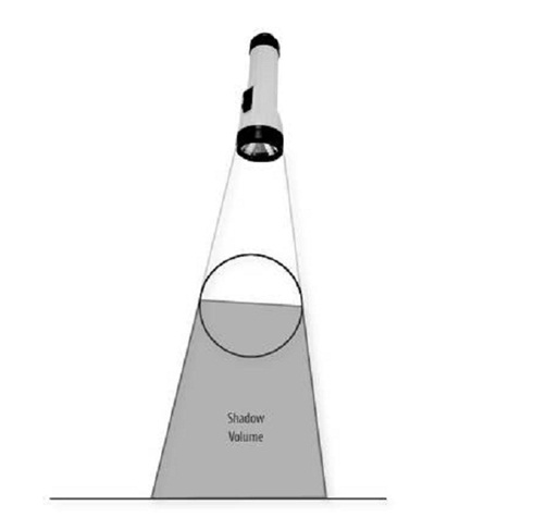
In the second pass, the shadows are composited with the existing contents of the frame buffer. To do this compositing operation, we render the shadow volume (i.e., the region in which the light source is occluded) for each shadow casting object. In the case of a sphere, computing the shadow volume is relatively easy. The sphere's shadow is in the shape of a truncated cone, where the apex of the cone is at the light source. One end of the truncated cone is at the center of the sphere (see Figure 13.2). (It is somewhat more complex to compute the shadow volume for an object defined by polygons, but the same principle applies.)
Figure 13.2. The shadow volume for a sphere
We composite shadows with the existing geometry by rendering the polygons that define the shadow volume. This allows our second pass shader to be applied only to regions of the image that might be in shadow. 通过渲染定义阴影体的多边形,我们把阴影与现有的几何信息合成。这可以让我们执行第二个pass的着色器仅仅只对图像上那些可能处在阴影中的区域进行渲染。
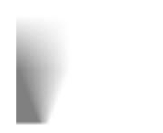
To draw a shadow, we use the texture map shown in Figure 13.3. This texture map expresses how much a visible surface point is in shadow relative to a shadow-casting object (i.e., how much its value is attenuated) based on a function of two values: 1) the squared distance from the visible surface point to the central axis of the shadow volume, and 2) the distance from the visible surface point to the center of the shadow-casting object. The first value is used as the s coordinate for accessing the shadow texture, and the second value is used as the t coordinate. The net result is that shadows are relatively sharp when the shadow-casting object is very close to the fragment being tested and the edges become softer as the distance increases.
Figure 13.3. A texture map used to generate soft shadows
In the second pass of the algorithm, we do the following:
在算法的第二个pass中,我们做如下的操作:
1. Draw the polygons that define the shadow volume. Only the fragments that could possibly be in shadow are accessed during this rendering operation. 画定义阴影体的多边形。在这次渲染操作中,只有那些可能处在阴影中的像素受影响。
2. For each fragment rendered,对每一个渲染的像素,
a. Look up the camera depth value for the fragment as computed in the first pass. 查询些像素在第一个pass中计算出的照相机深度值。
b. Calculate the coordinates of the visible surface point in the local space of the shadow volume. In this space, the z axis is the axis of the shadow volume and the origin is at the center of the shadow-casting object. The x component of this coordinate corresponds to the distance from the center of the shadow-casting object and is used directly as the second coordinate for the shadow texture lookup. 在阴影体的局部空间内,计算可见面的点的坐标。在此空间中,Z轴是阴影体的轴线,原点在被投影物体的中心。些坐标的X分量对应着该点到被投影物体的中心的的距离,它可以直接用作查找阴影纹理时的第二个坐标。
c. Compute the squared distance between the visible surface point and the z axis of the shadow volume. This value becomes the first coordinate for the texture lookup. 计算可见面上点到阴影体的Z轴的距离的平方。这个值将会作为查找阴影纹理时的第一个坐标。
d. Access the shadow texture by using the computed index values to retrieve the light attenuation factor and store this in the output fragment's alpha value. The red, green, and blue components of the output fragment color are each set to 0. 用前面计算出的索引值从阴影纹理中读取光照衰减因子,并把它存在输出像素的alpha值中。把输出像素的R,G,B分量分别设为0。
e. Compute for the fragment the light attenuation factor that will properly darken the existing frame buffer value. For the computation, enable fixed functionality blending, set the blend mode source function to GL_SRC_ALPHA, and set the blend destination function to GL_ONE. 计算像素的光照衰减因子,它可能使现有的帧缓存中的值变暗。计算时,打开固定功能混合,设置混合模式源函数为GL_SRC_ALPHA,设置混合目标函数为GL_ONE。
Because the shadow (second pass) shader is effectively a 2D compositing operation, the texel it reads from the depth texture must exactly match the pixel in the framebuffer it affects. So the texture coordinate and other quantities must be bilinearly interpolated without perspective correction. We interpolate by ensuring that w is constant across the polygondividing x, y, and z by w and then setting w to 1.0 does the job. Another issue is that when the viewer is inside the shadow volume, all faces are culled. We handle this special case by drawing a screen-sized quadrilateral since the shadow volume would cover the entire scene.
13.3.1. Shaders for First Pass
The shaders for the first pass of the volume shadow algorithm are shown in Listings 13.8 and 13.9. In the vertex shader, to accomplish the standard rendering of the geometry (which in this specific case is all texture mapped), we just call ftransform and pass along the texture coordinate. The other lines of code compute the normalized value for the depth from the vertex to the camera plane. The computed value, CameraDepth, is stored in a varying variable so that it can be interpolated and made available to the fragment shader.
To render into two buffers by using a fragment shader, the application must call glDrawBuffers and pass it a pointer to an array containing symbolic constants that define the two buffers to be written. In this case, we might pass the symbolic constant GL_BACK_LEFT as the first value in the array and GL_AUX0 as the second value. This means that gl_FragData[0] will be used to update the value in the soon-to-be-visible framebuffer (assuming we are double-buffering) and the value for gl_FragData[1] will be used to update the value in auxiliary buffer number 0. Thus,the fragment shader for the first pass of our algorithm contains just two lines of code (Listing 13.9).
Listing 13.8. Vertex shader for first pass of soft volume shadow algorithm
| uniform vec3 CameraPos; uniform vec3 CameraDir; uniform float DepthNear; uniform float DepthFar;
varying float CameraDepth; // normalized camera depth varying vec2 TexCoord;
void main() { // offset = vector to vertex from camera's position vec3 offset = (gl_Vertex.xyz / gl_Vertex.w) - CameraPos;
// z = distance from vertex to camera plane float z = -dot(offset, CameraDir);
// Depth from vertex to camera, mapped to [0,1] CameraDepth = (z - DepthNear) / (DepthFar - DepthNear);
// typical interpolated coordinate for texture lookup TexCoord = gl_MultiTexCoord0.xy;
gl_Position = ftransform(); }
|
Listing 13.9. Fragment shader for first pass of soft volume shadow algorithm
| uniform sampler2D TextureMap;
varying float CameraDepth; varying vec2 TexCoord;
void main() { // draw the typical textured output to visual framebuffer gl_FragData[0] = texture2D(TextureMap, TexCoord);
// write "normaliized vertex depth" to the depthmap's alpha. gl_FragData[1] = vec4(vec3(0.0), CameraDepth); } |
13.3.2. Shaders for Second Pass
The second pass of our shadow algorithm is responsible for compositing shadow information on top of what has already been rendered. After the first pass has been completed, the application must arrange for the depth information rendered into auxiliary buffer 0 to be made accessible for use as a texture. There are several ways we can accomplish this. One way is to set the current read buffer to auxiliary buffer 0 by calling glReadBuffer with the symbolic constant GL_AUX0, and then call glCopyTexImage2d to copy the values from auxiliary buffer 0 to a texture that can be accessed in the second pass of the algorithm. (A higher performance method that avoids an actual data copy is possible if the EXT_framebuffer_objects extension is used. This extension is expected to be promoted to the OpenGL core in OpenGL 2.1.)
In the second pass, the only polygons rendered are the ones that define the shadow volumes for the various objects in the scene. We enable blending by calling glEnable with the symbolic constant GL_BLEND, and we set the blend function by calling glBlendFunc with a source factor of GL_ONE and a destination factor of GL_SRC_ALPHA. The fragment shader outputs the shadow color and an alpha value obtained from a texture lookup operation. This alpha value blends the shadow color value into the frame buffer.
The vertex shader for the second pass (see Listing 13.10) is responsible for computing the coordinates for accessing the depth values that were computed in the first pass. We accomplish the computation by transforming the incoming vertex position, dividing the x, y, and z components by the w component, and then scaling and biasing the x and y components to transform them from the range [1,1] into the range [0,1]. Values for ShadowNear and ShadowDir are also computed. These are used in the fragment shader to compute the position of the fragment relative to the shadow-casting object.
Listing 13.10. Vertex shader for second pass of soft volume shadow algorithm
|
uniform mat3 WorldToShadow; uniform vec3 SphereOrigin;
uniform vec3 CameraPos; uniform vec3 CameraDir; uniform float DepthNear; uniform float DepthFar;
varying vec2 DepthTexCoord; varying vec3 ShadowNear; varying vec3 ShadowDir;
void main() { vec4 tmp1 = ftransform(); gl_Position = tmp1;
// Predivide out w to avoid perspective-correct interpolation. // The quantities being interpolated are screen-space texture // coordinates and vectors to the near and far shadow plane, // all of which have to be bilinearly interpolated. // This could potentially be done by setting glHint, // but it wouldn't be guaranteed to work on all hardware.
gl_Position.xyz /= gl_Position.w; gl_Position.w = 1.0;
// Grab the transformed vertex's XY components as a texcoord // for sampling from the depth texture from pass 1. // Normalize them from [0,0] to [1,1]
DepthTexCoord = gl_Position.xy * 0.5 + 0.5;
// offset = vector to vertex from camera's position vec3 offset = (gl_Vertex.xyz / gl_Vertex.w) - CameraPos;
// z = distance from vertex to camera plane float z = -dot(offset, CameraDir);
vec3 shadowOffsetNear = offset * DepthNear / z; vec3 shadowOffsetFar = offset * DepthFar / z;
vec3 worldPositionNear = CameraPos + shadowOffsetNear; vec3 worldPositionFar = CameraPos + shadowOffsetFar;
vec3 shadowFar = WorldToShadow * (worldPositionFar - SphereOrigin); ShadowNear = WorldToShadow * (worldPositionNear - SphereOrigin); ShadowDir = shadowFar - ShadowNear; } |
The fragment shader for the second pass is shown in Listing 13.11. In this shader, we access the cameraDepth value computed by the first pass by performing a texture lookup. We then map the fragment's position into the local space of the shadow volume. The mapping from world to shadow space is set up so that the center of the occluding sphere maps to the origin, and the circle of points on the sphere at the terminator between light and shadow maps to a circle in the YZ plane.
The variables d and l are respectively the distance along the shadow axis and the squared distance from it. These values are used as texture coordinates for the lookup into the texture map defining the shape of the shadow.
With the mapping described above, points on the terminator map to a circle in the YZ plane. The texture map has been painted with the transition from light to shadow occurring at s=0.5; to match this, the mapping from world to shadow is set up so that the terminator circle maps to a radius of sqrt(0.5).
Finally, the value retrieved from the shadow texture is used as the alpha value for blending the shadow color with the geometry that has already been rendered into the frame buffer.
Listing 13.11. Fragment shader for second pass of soft volume shadow algorithm
|
uniform sampler2D DepthTexture; uniform sampler2D ShadowTexture;
varying vec2 DepthTexCoord; varying vec3 ShadowNear; varying vec3 ShadowDir;
const vec3 shadowColor = vec3(0.0);
void main() { // read from DepthTexture // (depth is stored in texture's alpha component) float cameraDepth = texture2D(DepthTexture, DepthTexCoord).a;
vec3 shadowPos = (cameraDepth * ShadowDir) + ShadowNear; float l = dot(shadowPos.yz, shadowPos.yz); float d = shadowPos.x;
// k = shadow density: 0=opaque, 1=transparent // (use texture's red component as the density) float k = texture2D(ShadowTexture, vec2(l, d)).r;
gl_FragColor = vec4(shadowColor, k); } |
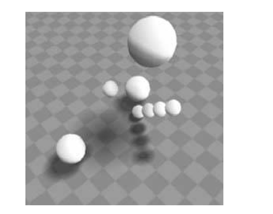
Figure 13.4 shows the result of this multipass shading algorithm in a scene with several spheres. Note how the shadows for the four small spheres get progressively softer edges as the spheres increase in distance from the checkered floor. The large sphere that is farthest from the floor casts an especially soft shadow.
Figure 13.4. Screen shot of the volume shadows shader in action.
Notice that spheres that are farther from the surface have shadows with softer edges.
The interesting part of this deferred shading approach is that the volumetric effects are implemented by rendering geometry that bounds the volume of the effect. This almost certainly means processing fewer vertices and fewer fragments. The shaders required are relatively simple and quite fast. Instead of rendering the geometry once for each light source, the geometry is rendered just once, and all the shadow volumes due to all light sources can be rendered in a single compositing pass. Localized effects such as shadow maps, decals, and projective textures can be accomplished easily. Instead of having to write tricky code to figure out the subset of the geometry to which the effect applies, you write a shader that is applied to each pixel and use that shader to render geometry that bounds the effect. This technique can be extended to render a variety of different effectsvolumetric fog, lighting, and improved caustics to name a few.


 713
713


 被折叠的 条评论
为什么被折叠?
被折叠的 条评论
为什么被折叠?
 到【灌水乐园】发言


