


Xilinx IOBUF 的用法
一、概念
1. 基本概念
应用场景: 在vivado中,连接的管脚的信号一般都会自动添加OBUF或IBUF。但是对于inout类型的接口,不会主动添加IOBUF,因为in/out切换需要控制信号,需要用户自己分配好。
Xilinx官网原文: The IOBUF primitive is needed when bidirectional signals require both an input buffer and a 3-state output buffer with an active-High 3-state T pin. The IOBUF is a generic IOBUF. A logic-High on the T pin disables the output buffer. When the output buffer is 3-stated (T = High), the input buffer and any on-die receiver termination (uncalibrated or DCI) are ON. When the output buffer is not 3-stated (T = Low), any on-die receiver termination (uncalibrated or DCI) is disabled.
I/O attributes that do not impact the logic function of the component such as IOSTANDARD, DRIVE and SLEW should be supplied to the top-level port via an appropriate property. For details on applying such properties to the associated port, see the Vivado Design Suite Properties Reference Guide (UG912).
个人翻译: 当双向信号需要输入缓冲区和带active-High 3态T引脚的3态输出缓冲区时,需要IOBUF原语。IOBUF是一个通用的IOBUF。T为高电平时关闭output buffer(I端口)。当output buffer为3-state (T = High)时,input buffer和任何固定接收器终端(未校准或DCI)均为有效。当输出缓冲区不是3-state (T = Low)时,任何固定接收器终端(未校准或DCI)都是禁用的。
不影响组件逻辑功能的I/O属性(如IOSTANDARD、DRIVE和kill)应该通过适当的属性提供给顶级端口。有关将这些属性应用到相关端口的详细信息,请参见Vivado设计套件属性参考指南(UG912)。
Vivado原语:
// IOBUF: Single-ended Bi-directional Buffer
//        All devices
// Xilinx HDL Language Template, version 2017.2

IOBUF #(
      .DRIVE(12), // Specify the output drive strength
      .IBUF_LOW_PWR("TRUE"),  // Low Power - "TRUE", High Performance = "FALSE"
      .IOSTANDARD("DEFAULT"), // Specify the I/O standard
      .SLEW("SLOW") // Specify the output slew rate
   ) IOBUF_inst (
      .O(O),   // 1-bit output: Buffer output
      .I(I),   // 1-bit input: Buffer input
      .IO(IO), // 1-bit inout: Buffer inout (connect directly to top-level port)
      .T(T)    // 1-bit input: 3-state enable input
   );
个人理解: 这玩意儿的解释有点绕,我们结合结构图、原文、原语来总结一下,大致是这么个意思:
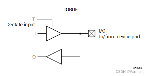
首先,我为什么说它绕,因为IOBUF的O指的是IO_pin >> FPGA,也就是说这里的Output输出的主语是IO_pin,而不是FPGA;这里的 I 指的是IO_Pin << FPGA,同样主语是IO_pin,这里指的是输入到IO_pin。所以第一次使用的时候容易弄混。
再与结构图结合就很容易理解了,三态门T控制的是I端口能否有效输入:
- T拉高时,I端口停止工作,O端口向FPGA内部输出信号;
- T拉低时,I端口向IO_pin输入来自FPGA内部的信号,此时 O = I(因为O端口从这个方向上来说也是 I 的分支);
2. 硬件结构
2.1 IOBUF
官网原图:

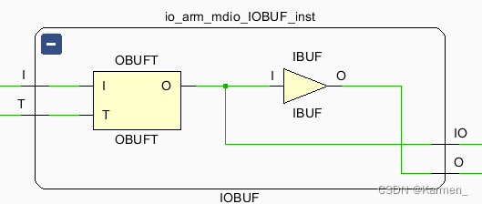
Vivado综合后的RTL视图:
真值表:
|
|
|
| |
|---|---|---|---|
|
|
|
|
|
|
|
|
|
|
|
|
|
|
|
|
|
|
|
|
接口描述:
| Port | Direction | Width | Function | 带有个人情感色彩的翻译 |
|---|---|---|---|---|
| I | Input | 1 | Input of OBUF. Connect to the logic driving the output port. | OBUF的输入端,连接到Output端口的逻辑驱动 |
| IO | Inout | 1 | Bidirectional port to be connected directly to top-level inout port. | 双向端口被直接连接到顶层的inout端口 |
| O | Output | 1 | Output path of the buffer. | IOBUF的输出路径 |
| T | Input | 1 | 3-state enable input signifying whether the buffer acts as an input or output. | 3态门启用输入,表示IOBUF是作为输入还是作为输出。 |
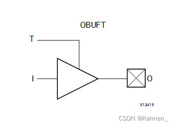
2.2 OBUFT
真值表:
|
|
| |
|---|---|---|
|
|
|
|
|
|
|
|
|
|
|
|
|
|
|
|
接口描述:
| Port | Direction | Width | Function | 带有个人偏见的翻译 |
|---|---|---|---|---|
| I | Input | 1 | Input of OBUF. Connect to the logic driving the output port. | OBUF的输入端,连接到Output端口的逻辑驱动 |
| O | Output | 1 | Output of OBUF to be connected directly to top-level output port. | OBUF的输出端被直接连接到顶层的output端口 |
| T | Input | 1 | 3-state enable input. | 三态门使能输入 |
二、实例
首先我们想象这样一个应用场景:
因为某些原因,ARM不能直接连接到PHY芯片上,所以需要通过FPGA间接与PHY芯片相连接,这个时候我们就有以下引脚:
input  i_arm_mdc,
inout  io_arm_mdio,
output o_phy_mdc,
inout  io_phy_mdio
而根据MDIO协议:


IO端口切换输入输出模式的根据是OP位,所以我们可以先设置一系列寄存器来存储io_arm_mdio的input内容,以及读写变化使能。
reg      	        s_mdio_rd_en;
reg      [35:00]    s_mdio_word ;
reg      [01:00]    s_mdio_op   ;
reg      [05:00]    s_cnt_mdio  ;
reg                 s_add_mdio  ;
wire				s_arm_out	;
wire                s_phy_out	;

assign o_phy_mdc = i_arm_mdc	;

always @(posedge i_arm_mdc or negedge i_rst_n)begin
    if(!i_rst_n) begin
	    s_mdio_word <= 36'b0;
	end
	else begin
		s_mdio_word <= {s_mdio_word[34:00],s_arm_out};
	end
end

/* ---- mdio contrl ---- */
always @(posedge i_arm_mdc or negedge i_rst_n) begin
    if (!i_rst_n) begin
        s_add_mdio <= 1'b0;
        s_mdio_op  <= 1'b0;
    end
    else begin
		if((s_mdio_word==36'hffffffff6||s_mdio_word==36'hffffffff5) && s_mdio_trans_cnt == 8'd35)
            s_add_mdio <= 1'b1;
		else if(s_cnt_mdio >= 16'd27)
            s_add_mdio <= 1'b0;
        else
            s_add_mdio <= s_add_mdio;
        if (s_add_mdio)
            s_cnt_mdio <= s_cnt_mdio + 1'b1;
        else
            s_cnt_mdio <= 1'b0;
		if(s_mdio_word==36'hffffffff6 && s_mdio_trans_cnt == 8'd35)
            s_mdio_op <= Read_bits;
        else if (s_mdio_word==36'hffffffff5 && s_mdio_trans_cnt == 8'd35)
            s_mdio_op <= Write_bits;
		else
			s_mdio_op <= s_mdio_op;
	end
end

always @(posedge i_arm_mdc or negedge i_rst_n)begin
    if(!i_rst_n)begin
		s_mdio_rd_en <= 1'b0;
	end
	else begin
		if(s_cnt_mdio>=6'd9 && s_mdio_op == Read_bits)/* 5-bit PHY_ADDR + 5-bit Reg_ADDR = 10-bit */
			s_mdio_rd_en <= 1'b1;
		else
			s_mdio_rd_en <= 1'b0;
	end
end
在需要的参数都准备好后,就可以开始使用原语了:
IOBUF #(
            .DRIVE(12),              // Specify the output drive strength
            .IBUF_LOW_PWR("TRUE"),   // Low Power - "TRUE", High Performance = "FALSE"
            .IOSTANDARD("DEFAULT"),  // Specify the I/O standard
            .SLEW("SLOW")            // Specify the output slew rate
    ) IOBUF_inst_arm (
            .O (s_arm_out      ),    //
            .IO(io_arm_mdio    ),    //
            .I (s_phy_out     ),    //
            .T (!s_mdio_rd_en )     // 3-state enable input, high=input, low=output
    );
IOBUF #(
            .DRIVE(12),              // Specify the output drive strength
            .IBUF_LOW_PWR("TRUE"),   // Low Power - "TRUE", High Performance = "FALSE"
            .IOSTANDARD("DEFAULT"),  // Specify the I/O standard
            .SLEW("SLOW")            // Specify the output slew rate
    ) IOBUF_inst_phy (
            .O (s_phy_out      ),    //
            .IO(io_phy_mdio    ),    //
            .I (s_arm_out      ),    //
            .T (s_mdio_rd_en  )     // 3-state enable input, high=input, low=output
    );
最后综合出来的结果就是这个样子:


 3622
3622


 被折叠的 条评论
为什么被折叠?
被折叠的 条评论
为什么被折叠?
 到【灌水乐园】发言


