About the ARM PrimeCell GPIO

The PrimeCell GPIO is an Advanced Microcontroller Bus Architecture (AMBA)
compliant System-on-Chip (SoC) peripheral that is developed, tested, and licensed by
ARM.
The PrimeCell GPIO is an AMBA slave module that connects to the AdvancedPeripheral Bus (APB). The PrimeCell GPIO provides eight programmable inputs oroutputs that you can control in two modes:

• software mode through an APB bus interface
• hardware mode through a hardware control interface.

You can create ports of different widths (for example 16, 24, 32, and 40 bits) by multipleinstantiation. An interrupt interface is provided to configure any number of pins asinterrupt sources. You can generate interrupts depending on a level, or a transitional value of a pin. At system reset, PrimeCell GPIO lines default to inputs. The PrimeCell
GPIO interfaces with input and output pad cells using a data input, data output, and output enable per pad.
Figure 1-1 on page 1-3 shows the PrimeCell GPIO interfaces.
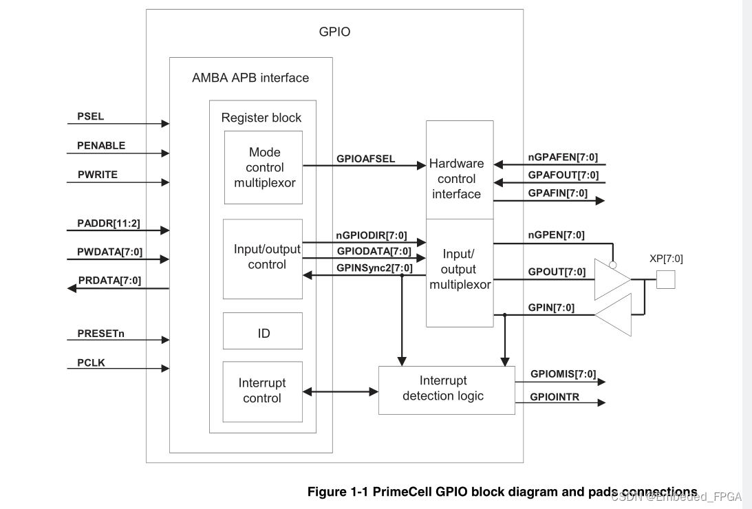
在这里插入图片描述
1.1.1
Features of the PrimeCell GPIO
The PrimeCell GPIO offers:
• Compliance to the AMBA Specification (Rev 2.0) onwards for easy integration into SoC implementation.
• Eight individually programmable input/output pins, default to input at reset.
• Scalability by multiple instantiation to 16, 24, 32, 40, or more bits.
• Programmable interrupt generation capability, from a transition or a level condition, on any number of pins.
• Hardware control capability of PrimeCell GPIO lines for different system
configurations.
• Bit masking in both read and write operations through address lines.
• Identification registers that uniquely identify the PrimeCell GPIO.

2.1
PrimeCell GPIO overview
The PrimeCell GPIO is an Advanced Microcontroller Bus Architecture (AMBA) bus slave that connects to the AMBA Advanced Peripheral Bus (APB). It provides eight programmable inputs or outputs that you can control in two modes:
• software mode through an APB bus interface
• hardware mode through a hardware control interface.
The CPU accesses data, control, and status information of the PrimeCell GPIO through the APB bus interface.
The PrimeCell GPIO peripheral includes the following registers:
• Data direction register
• Data register
• Interrupt control registers
• Mode control select register
• Identification registers on page 2-3.
2.1.1
Data direction register
The data direction register is eight bits wide and configures each pin as an input or output.
2.1.2
Data register The data register is eight bits wide and is used to:
• read the value input on those PrimeCell GPIO lines that are configured as inputs
• program the value on those PrimeCell GPIO lines that are configured as outputs.
The same data register appears at 256 locations in the memory map. This allows you to use the address bus [9:2] as an additional bit masking feature.
2.1.3
Interrupt control registers
The PrimeCell GPIO has interrupt generation capability. You can configure any number of the external PrimeCell GPIO lines independently to trigger an interrupt through its corresponding bit in the seven interrupt registers.
2.1.4
Mode control select register
The PrimeCell GPIO lines can be controlled by software through the APB bus or by hardware through the hardware control interface. The mode of each PrimeCell GPIO line is selected by the mode control select register.

When you enable hardware control in a particular line, control and data transfer over
this line is provided from an auxiliary source.
2.1.5
Identification registers
The PrimeCell GPIO identification registers contain peripheral and BIOS information that uniquely identifies the peripheral. An automatically configuring BIOS can scan through memory searching for the BIOS ID number. Once found, the BIOS can read the peripheral ID numbers and automatically configure itself.

2.2
PrimeCell GPIO functional description
Figure 2-1 shows a block diagram of the PrimeCell GPIO.
在这里插入图片描述
2.2.1
AMBA APB interface
The AMBA APB is a local secondary bus that provides a low-power extension to the higher bandwidth AMBA Advanced High-performance Bus (AHB), within the AMBA system hierarchy. The AMBA APB groups narrow-bus peripherals to avoid loading the system bus, and provides an interface using memory-mapped registers that are accessed under programmed control.
The AMBA APB interface generates read and write decodes for accesses to control, interrupt, and data registers within the PrimeCell GPIO. A read-only decode is provided to access the ID codes.
The AMBA APB interface implements the storage elements for the data, data direction, mode control, interrupt interface, and identification registers.
2.2.2
Interrupt detection logic
The PrimeCell GPIO has the ability to generate mask-programmable interrupts based on the level, or transitional value of any of its PrimeCell GPIO lines.
The General Purpose Input Output Interrupt (GPIOINTR) indicates to an interrupt controller that an interrupt occurred in one or more of the PrimeCell GPIO lines.You can configure interrupts so that they are generated either on a change in the level, or on an edge of the PrimeCell GPIO line. The edge and level on which the interrupt must be
generated is programmable.Seven registers in the AMBA APB interface, each controlling a different feature or condition in the interrupt triggering chain, allow thefollowing functionality:
• interrupt generation either on a change in the level, one edge, or both edges of the PrimeCell GPIO line
• reading raw and masked interrupt status
• reading from and writing to the interrupt enable
• interrupt clear (write-only).
Each input/output line has a corresponding masked interrupt output line. Setting the appropriate mask bit HIGH enables the interrupt. GPIOINTR is the combined interrupt output of the PrimeCell GPIO masked interrupt status lines. It indicates to the interrupt controller that this block is requesting service from one or more of its interrupt sources.
Provision of individual outputs as well as a combined interrupt output, allows you to use either a global interrupt service routine or modular device drivers to handle interrupts.

2.2.3
Mode control
You can control the PrimeCell GPIO lines by software through the APB bus, or by hardware through the hardware control interface. Select the mode of each PrimeCell GPIO line using the mode control select register (GPIOAFSEL).
When software control mode is enabled (default) the data direction is controlled by the data direction register. Data writes and reads are then performed through the APB interface.
When hardware control mode is enabled, data direction is controlled through the auxiliary port direction control pins. Similarly, data is written and read through this port,
but pin status can also be read through the APB interface.

2.3
PrimeCell GPIO operation
The operation of the PrimeCell GPIO is described in the following sections:
• Interface reset
• Interface configuration
• Operation of the input/output lines on page 2-8
• Interrupt operation on page 2-10
• Mode control on page 2-12.
2.3.1
Interface reset
All block registers are cleared during power-on-reset (LOW). This disables the output drivers for the Primecell GPIO lines, so that the pins are configured as inputs.
2.3.2
Interface configuration
On application of PRESETn as LOW:
• interrupts in the desired line are disabled by clearing the corresponding bit in GPIOIE
• all registers are cleared to zero
• input and output pins are configured as inputs
• interrupts to the external world are all masked as disabled
• raw interrupts are cleared to zero
• edge triggered interrupts are selected as source.
Recommendations
If you want to generate edge-triggered interrupts you must perform the following initialization sequence to avoid spurious interrupts being interpreted by the system:
• program GPIOIBE appropriately as individual or both-edge detection
• program GPIOIEV, if you have selected individual edge transactions previously
• program GPIOIS to select edge-triggered path
• apply three clock pulses to clean interrupt pipeline
• ensure GPIN[7:0] bus remains stable throughout this operation
• clear all interrupts by writing 0xFF to GPIOIC
• program GPIOIE to enable interrupts.

  • 22
    点赞
  • 18
    收藏
    觉得还不错? 一键收藏
  • 0
    评论

“相关推荐”对你有帮助么?

  • 非常没帮助
  • 没帮助
  • 一般
  • 有帮助
  • 非常有帮助
提交
评论
添加红包

请填写红包祝福语或标题

红包个数最小为10个

红包金额最低5元

当前余额3.43前往充值 >
需支付:10.00
成就一亿技术人!
领取后你会自动成为博主和红包主的粉丝 规则
hope_wisdom
发出的红包
实付
使用余额支付
点击重新获取
扫码支付
钱包余额 0

抵扣说明:

1.余额是钱包充值的虚拟货币,按照1:1的比例进行支付金额的抵扣。
2.余额无法直接购买下载,可以购买VIP、付费专栏及课程。

余额充值