


串口发送的时序比较简单,用上线性序列机可以轻松实现,要注意的是波特率对应时钟周期的计算和适配多个波特率的设计。模块信号流向如下:
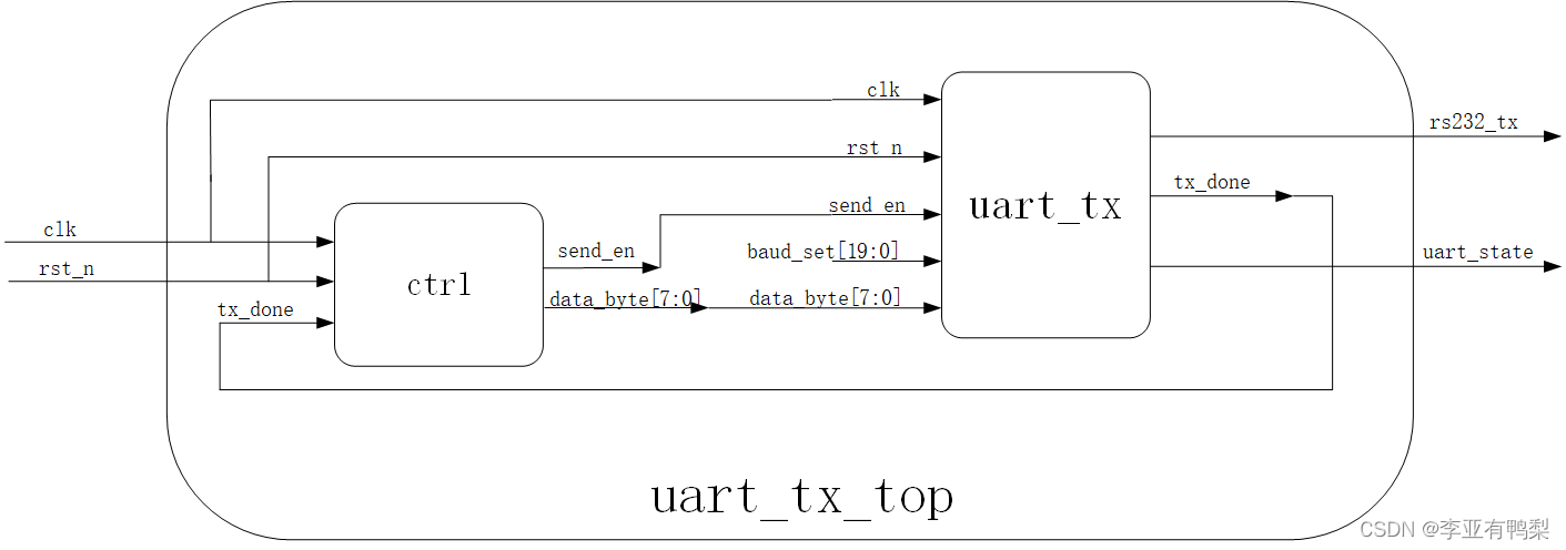
在send_en高电平期间,模块发送一个字节的数据,发完后拉高tx_done一个时钟周期。可以指定波特率以及在模块发送数据期间通过uart_state信号向外部传递模块正忙的信息。
波特率相关计算:9600为例,代表在该工作模式下,一秒钟发送9600 bit数据。这样根据20ns的时钟周期易得出发送一个bit需要5208个时钟周期的时间。
得到了每个bit的发送所用时间,再设计一个线性序列机,就可以实现功能了。
一、uart_tx的逻辑设计和仿真
逻辑设计
module uart_tx
(
input wire clk ,
input wire rst_n ,
input wire send_en ,
input wire [19:0] baud_set ,
input wire [7:0] data_byte ,
output reg rs232_tx ,
output wire tx_done ,
output wire uart_state
);
reg [15:0] baud_cnt_max;
reg [15:0] baud_cnt;
reg [3:0] baud_cnt_overflow;
//实现波特率的适配
always@(posedge clk or negedge rst_n)
if(!rst_n)
baud_cnt_max <= 16'd434;
else begin
case(baud_set)
20'd9600 : baud_cnt_max <= 16'd5208;
20'd19200 : baud_cnt_max <= 16'd2604;
20'd115200 : baud_cnt_max <= 16'd434;
default : baud_cnt_max <= 16'd5208;
endcase
end
//序列机计数器1
always@(posedge clk or negedge rst_n)
if(!rst_n)
baud_cnt <= 16'd0;
else if(send_en)
begin
if(baud_cnt == baud_cnt_max - 1'b1)
baud_cnt <= 16'd0;
else
baud_cnt <= baud_cnt + 1'b1;
end
else
baud_cnt <= 16'd0;
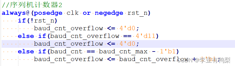
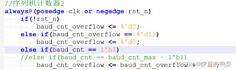
//序列机计数器2
always@(posedge clk or negedge rst_n)
if(!rst_n)
baud_cnt_overflow <= 4'd0;
else if(baud_cnt_overflow == 4'd11)
baud_cnt_overflow <= 4'd0;
else if(baud_cnt == baud_cnt_max - 1'b1)
baud_cnt_overflow <= baud_cnt_overflow + 1'b1;
//数据发送部分
always@(posedge clk or negedge rst_n)
if(!rst_n)
rs232_tx <= 1'b1;
else begin
case(baud_cnt_overflow)
4'd0 : rs232_tx <= 1'b1;//继续拉高,当作空闲态,避免baud_cnt_overflow清零时也在发数据
4'd1 : rs232_tx <= 1'b0;//起始位
4'd2 : rs232_tx <= data_byte[0];
4'd3 : rs232_tx <= data_byte[1];
4'd4 : rs232_tx <= data_byte[2];
4'd5 : rs232_tx <= data_byte[3];
4'd6 : rs232_tx <= data_byte[4];
4'd7 : rs232_tx <= data_byte[5];
4'd8 : rs232_tx <= data_byte[6];
4'd9 : rs232_tx <= data_byte[7];
4'd10 : rs232_tx <= 1'b1;//停止位
default : rs232_tx <= 1'b1;
endcase
end
assign tx_done = (baud_cnt_overflow == 4'd11)?1'b1:1'b0;
assign uart_state = !send_en;
endmodule
计数器1根据每个bit的发送时间来设计,计数最大值为一个bit的发送时间,受控于send_en。
计数器2对计数器1的溢出次数进行计数,作为数据发送的时刻基准。
数据发送部分,复位后数据线拉高,这是uart空闲时的常态。这里处理baud_cnt_overflow的0时刻要注意,最好将其归入空闲时刻(拉高),如果baud_cnt_overflowde 0时刻发送起始位,那么在baud_cnt_overflow计数器清零的时候(也许会因为没有发送任务而保持较长时间)还在发送0,可能会引起一些列问题,故干脆将0时刻将数据线拉高。
tb
`timescale 1ns/1ns
`define clk_period 20
module uart_tx_tb;

//============================<端口>==============================
reg clk;
reg rst_n;
reg send_en;

wire rs232_tx;
wire tx_done;
wire uart_state;
//================================================================
//==                         模块例化
//================================================================
uart_tx uart_tx_inst
(
    .clk         (clk),
    .rst_n       (rst_n),
    .send_en     (send_en),
    .baud_set    (20'd115200),
    .data_byte   (8'h12),

    .rs232_tx    (rs232_tx),
    .tx_done     (tx_done),
    .uart_state  (uart_state)
);


//================================================================
//==                         时钟信号
//================================================================
initial clk = 1'b1;
always #(`clk_period/2) clk = ~clk;

//================================================================
//==                       设计输入信号
//================================================================
initial begin
    rst_n = 0;
    send_en = 0;
    #201;
    rst_n = 1;
    #201;
    send_en = 1;
    #1000000;
    $stop;
end

endmodule
modelsim仿真

可以看到每个数据发送时间内,数据有序地放到了数据线上,也正常地发出了一个时钟周期地tx_done。
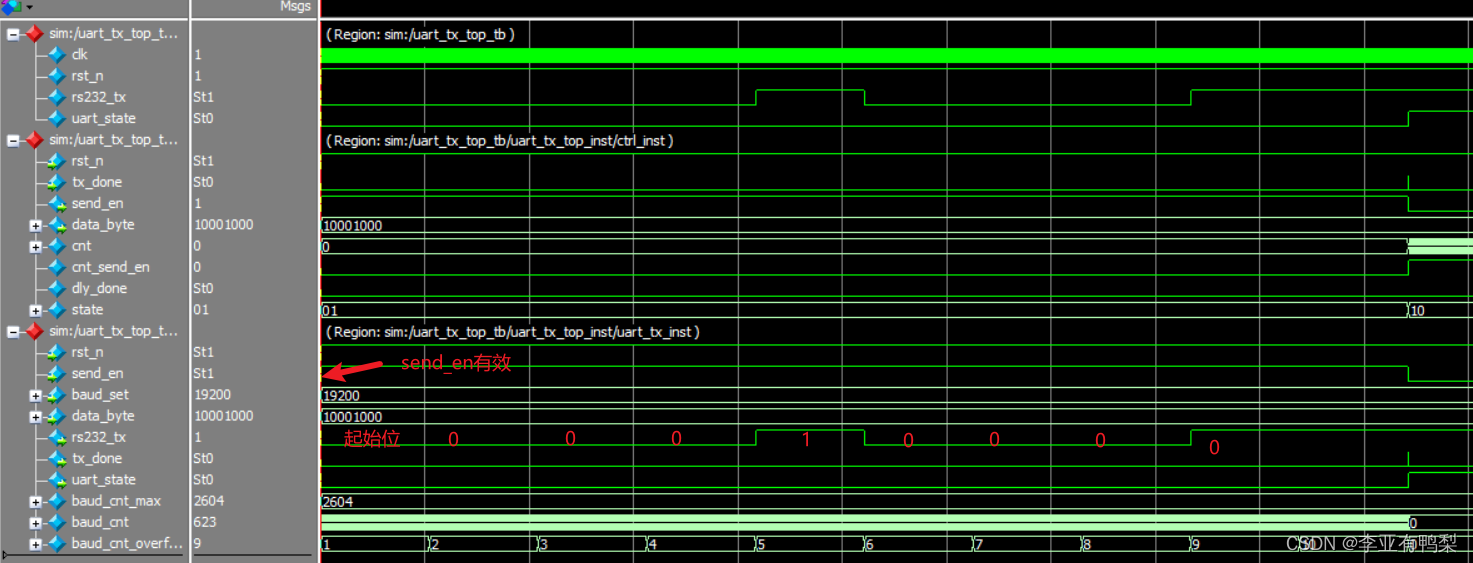
二、uart_tx_top模块地设计与仿真
由于ctrl模块就是控制数据发送模块隔一段时间发送一串数据,之前已经做过仿真,所以我就没有单独对ctrl模块仿真了。
逻辑设计
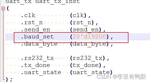
例化两个模块到顶层,指定波特率为19200。
module uart_tx_top
(
    input       wire                clk         ,
    input       wire                rst_n       ,

    output      wire                rs232_tx    ,
    output      wire                uart_state
);

wire send_en;
wire [7:0] data_byte;
wire tx_done;


uart_tx uart_tx_inst
(
    .clk         (clk),
    .rst_n       (rst_n),
    .send_en     (send_en),
    .baud_set    (20'd19200),
    .data_byte   (data_byte),

    .rs232_tx    (rs232_tx),
    .tx_done     (tx_done),
    .uart_state  (uart_state)
);


ctrl ctrl_inst
(
    .clk         (clk),
    .rst_n       (rst_n),
    .tx_done     (tx_done),

    .send_en     (send_en),
    .data_byte   (data_byte)
);

endmodule
tb
`timescale 1ns/1ns
`define clk_period 20
module uart_tx_top_tb;

//============================<端口>==============================
reg clk;
reg rst_n;

wire rs232_tx;
wire uart_state;
//================================================================
//==                         模块例化
//================================================================
uart_tx_top uart_tx_top_inst
(
    .clk         (clk),
    .rst_n       (rst_n),

    .rs232_tx    (rs232_tx),
    .uart_state  (uart_state)
);


//================================================================
//==                         时钟信号
//================================================================
initial clk = 1'b1;
always #(`clk_period/2) clk = ~clk;

//================================================================
//==                       设计输入信号
//================================================================
initial begin
    rst_n = 0;
    #201;
    rst_n = 1;
    #1000000;
    $stop;
end

endmodule
modelsim仿真
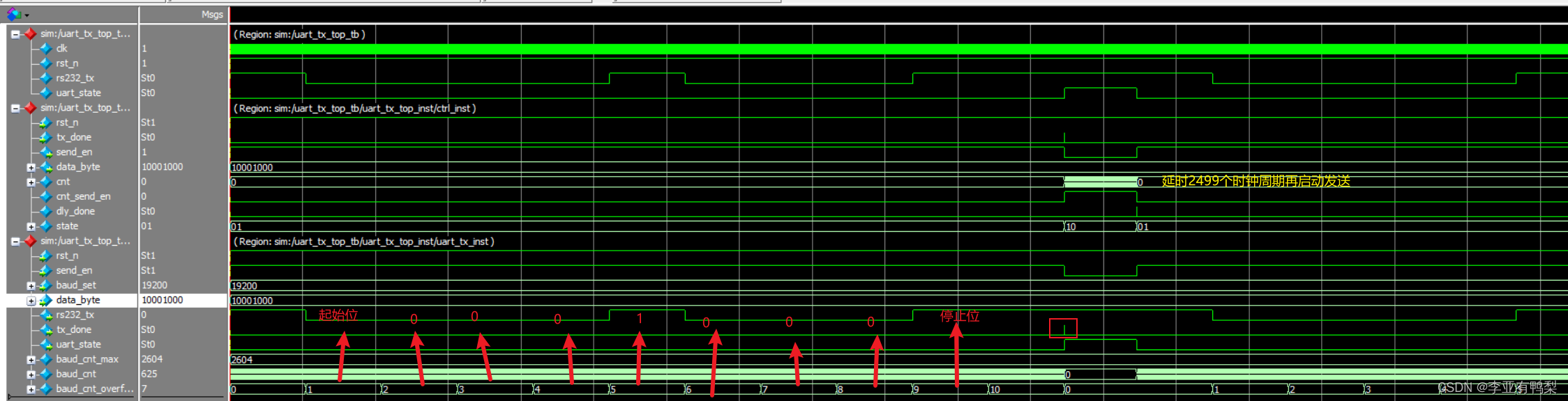
可以看到,在ctrl模块的控制下,间隔2500个时钟周期(图中标错了)发送一个字节的数据。其中tx_done、uart_state信号时序都是正常的。
三、优化
1.问题
由于在uart_tx模块中计数器2的baud_cnt_overflow对baud_cnt的计数最大值进行计数,这会使得模块在接收到send_en信号后至少延迟1个bit发送的时间才会发送起始位(1时刻发送起始位)。
2.解决
这么长的延迟是不允许的。由于只是单纯不想在0时刻发送数据和获得一个bit的计数时间,故改为baud_cnt_overflow对cnt == 1的时刻进行计数,大大优化了时序关系。
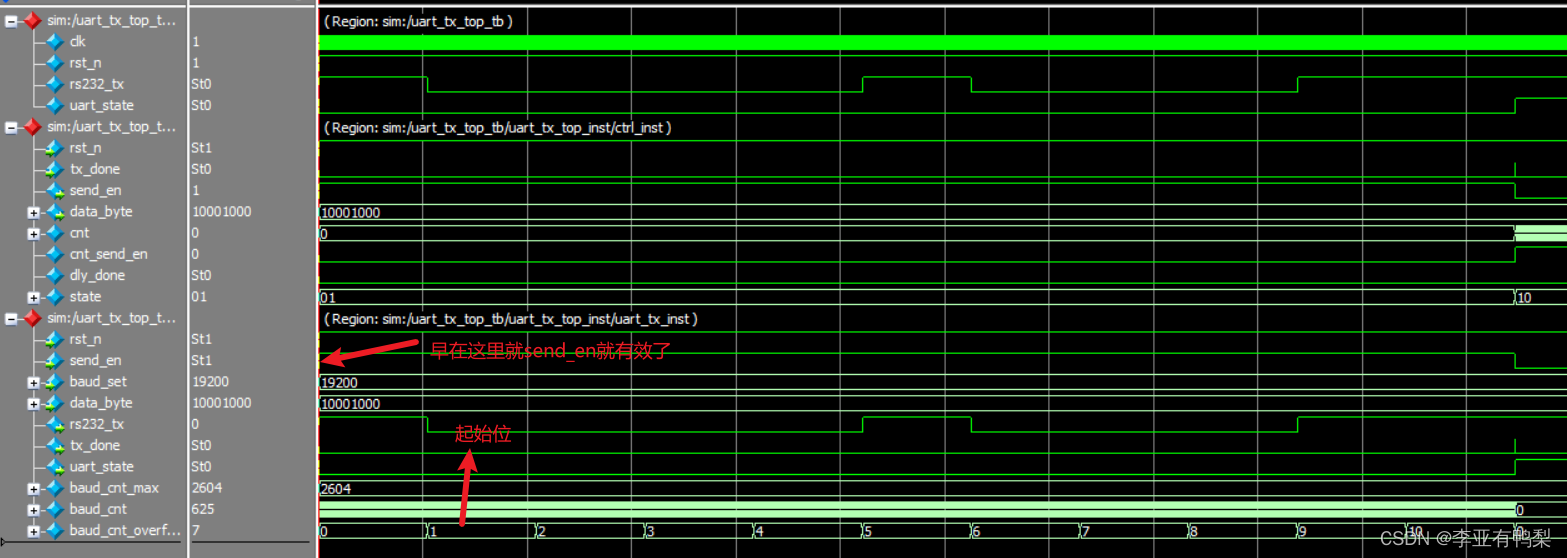
再来看看仿真
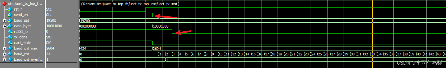
可以看到send_en有效后两个时间周期后就开始发送起始位。
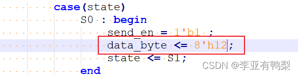
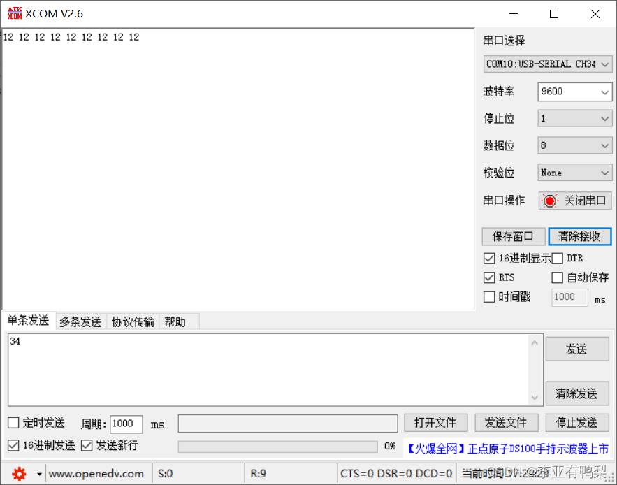
四、硬件验证
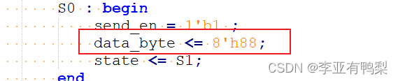
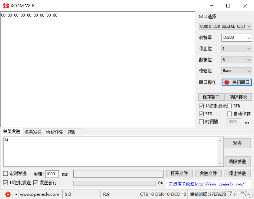
更改发送数据值和波特率

五、总结
用序列机实现了uart发送逻辑。


 9896
9896


 被折叠的 条评论
为什么被折叠?
被折叠的 条评论
为什么被折叠?
 到【灌水乐园】发言


