


一. 了解串口协议和RS-232标准,以及RS232电平与TTL电平的区别;了解"USB/TTL转232"模块(以CH340芯片模块为例)的工作原理。
串口协议是一种用于在设备之间进行数据通信的标准协议。RS-232则是一种常见的串口标准,定义了数据通信所需的物理连接、电气特性、信号规范和通信协议等方面的细节。
RS-232通常使用负电平来表示逻辑1,正电平来表示逻辑0。在RS-232标准中,逻辑1的电压范围为-3V至-15V,逻辑0的电压范围为+3V至+15V。
TTL(Transistor-Transistor Logic)电平,它通常用于数字电路中。TTL电平中,逻辑1通常被定义为高电平(约+5V至+3.3V),逻辑0被定义为低电平(约0V至+0.8V),两者的逻辑电平有明显的区别。
USB/TTL转RS-232模块(例如CH340芯片模块)的工作原理如下:
USB连接: 模块通过USB接口与计算机或其他USB主机设备连接,用于通信和供电。
USB转串口: 模块内部集成了USB转串口的功能,通过USB与计算机通信,并将数据转换为串口信号。
串口信号转换: 模块内部使用芯片(如CH340)将USB接收到的数据转换为RS-232电平或TTL电平信号,具体转换为哪种电平取决于模块的设计和用户的需求。
串口连接: 模块上通常提供了串口接口(如DB9接口),用户可以通过这些接口将模块连接到目标设备的串口接口上,进行数据通信。
总的来说,USB/TTL转RS-232模块通过USB接口与计算机连接,实现USB到串口信号的转换,然后将串口信号通过串口接口传输给目标设备,从而实现USB与RS-232或TTL设备之间的数据通信。
二. 掌握STM32的标准库开发的基本方法;掌握UART串口通信程序开发基本方法(效率较低的查询方式)。
1、用标准库方式,完成LED的点灯。
标准库代码实现:
#include "stm32f10x.h"

void GPIO_Configuration(void)
{
  GPIO_InitTypeDef GPIO_InitStructure;
  RCC_APB2PeriphClockCmd( RCC_APB2Periph_GPIOA , ENABLE);
  GPIO_InitStructure.GPIO_Pin = GPIO_Pin_0;
  GPIO_InitStructure.GPIO_Speed = GPIO_Speed_50MHz;

  GPIO_InitStructure.GPIO_Mode = GPIO_Mode_Out_PP;
  GPIO_Init(GPIOA, &GPIO_InitStructure);
}
void delay_ms(uint16_t time)
{
	uint16_t i = 0;
	while(time--)
	{
		i = 10000;
		while(i--);
	}
}
int main(void){
	  GPIO_Configuration();
    while (1)
		{
			GPIO_WriteBit(GPIOA,GPIO_Pin_0,Bit_RESET);
			delay_ms(500);
			GPIO_WriteBit(GPIOA,GPIO_Pin_0,Bit_SET);
						delay_ms(500);
    }
}
效果图:
2、采用标准库的查询方式(暂不使用中断方式),完成以下要求:
1)设置波特率为9600,1位停止位,无校验位;
2)STM32系统给上位机(win10)连续发送“hello windows!”。win10采用“串口助手”工具接收。
主程序:
#include "stm32f10x.h"
#include "Serial.h"
#include <string.h>
void delay_ms(uint16_t time)
{
	uint16_t i = 0;
	while(time--)
	{
		i = 10000;
		while(i--);
	}
}
int main(void)
{
uint8_t data[]={'h','e','l','l','o',' ','w','i','n','d','o','w','s','!'};

	Serial_Init();
//	Serial_SendByte();


	while(1)
	{
		delay_ms(1000);
		Serial_SendArray(data,14);


	}
}
串口c文件:
#include "stm32f10x.h"
void Serial_Init(void)
{
	RCC_APB2PeriphClockCmd(RCC_APB2Periph_USART1,ENABLE);
	RCC_APB2PeriphClockCmd(RCC_APB2Periph_GPIOA,ENABLE);

	GPIO_InitTypeDef GPIO_InitStructure;
  GPIO_InitStructure.GPIO_Pin = GPIO_Pin_9;
  GPIO_InitStructure.GPIO_Speed = GPIO_Speed_50MHz;
  GPIO_InitStructure.GPIO_Mode = GPIO_Mode_AF_PP;
  GPIO_Init(GPIOA, &GPIO_InitStructure);

	USART_InitTypeDef USART_InitStructure;
	USART_InitStructure.USART_BaudRate=9600;
	USART_InitStructure.USART_HardwareFlowControl=USART_HardwareFlowControl_None;
	USART_InitStructure.USART_Mode=USART_Mode_Tx;
	USART_InitStructure.USART_Parity=USART_Parity_No;
	USART_InitStructure.USART_StopBits=USART_StopBits_1;
	USART_InitStructure.USART_WordLength=USART_WordLength_8b;

	USART_Init(USART1,&USART_InitStructure);
	USART_Cmd(USART1,ENABLE);
}

void Serial_SendByte(uint8_t Byte)
{
	USART_SendData(USART1,Byte);
	while(USART_GetFlagStatus(USART1,USART_FLAG_TXE)==RESET);

}
void Serial_SendArray(uint8_t* Array, uint16_t Length)
{
uint16_t i;
for(i=0;i<Length;i++)
{
	Serial_SendByte(Array[i]);
}
}
串口头文件:
#ifndef __SERIAL_H
#define __SERIAL_H
void Serial_Init(void);
	void Serial_SendByte(uint8_t Byte);
	void Serial_SendArray(uint8_t* Array, uint16_t Length);


	#endif
实物图:
可以观察到,串口和ttl的信号输出频率都是一秒左右
3、采用标准库的查询方式完成以下要求:
STM32以查询方式接收上位机(win10)串口发来的数据,如果接收到“Y”则点亮链接到stm32上的一个LED灯;接收到“N”则熄灭LED灯。
主程序:
#include "stm32f10x.h"
#include "Serial.h"
#include <string.h>
void GPIO_Configuration(void)
{
  GPIO_InitTypeDef GPIO_InitStructure;
  RCC_APB2PeriphClockCmd( RCC_APB2Periph_GPIOA , ENABLE);
  GPIO_InitStructure.GPIO_Pin = GPIO_Pin_0;
  GPIO_InitStructure.GPIO_Speed = GPIO_Speed_50MHz;

  GPIO_InitStructure.GPIO_Mode = GPIO_Mode_Out_PP;
  GPIO_Init(GPIOA, &GPIO_InitStructure);
}
void delay_ms(uint16_t time)
{
	uint16_t i = 0;
	while(time--)
	{
		i = 10000;
		while(i--);
	}
}
int main(void)
{
	GPIO_Configuration();
		Serial_Init();
	uint8_t RxData;

	while(1)
	{
		if(USART_GetFlagStatus(USART1,USART_FLAG_RXNE)==SET)
		{
			RxData=USART_ReceiveData(USART1);
			if(RxData=='N')
			{

						GPIO_WriteBit(GPIOA,GPIO_Pin_0,Bit_SET);
				if(RxData=='Y')break;
			}
			if(RxData=='Y')
			{
								GPIO_WriteBit(GPIOA,GPIO_Pin_0,Bit_RESET);
					if(RxData=='N')break;

			}


	}
}
}
串口程序:
#include "stm32f10x.h"
void Serial_Init(void)

{
	RCC_APB2PeriphClockCmd(RCC_APB2Periph_USART1,ENABLE);
	RCC_APB2PeriphClockCmd(RCC_APB2Periph_GPIOA,ENABLE);

	GPIO_InitTypeDef GPIO_InitStructure;

  GPIO_InitStructure.GPIO_Pin = GPIO_Pin_9;
  GPIO_InitStructure.GPIO_Speed = GPIO_Speed_50MHz;
  GPIO_InitStructure.GPIO_Mode = GPIO_Mode_AF_PP;
  GPIO_Init(GPIOA, &GPIO_InitStructure);

	  GPIO_InitStructure.GPIO_Pin = GPIO_Pin_10;
  GPIO_InitStructure.GPIO_Speed = GPIO_Speed_50MHz;
  GPIO_InitStructure.GPIO_Mode = GPIO_Mode_IPU;
  GPIO_Init(GPIOA, &GPIO_InitStructure);

	USART_InitTypeDef USART_InitStructure;
	USART_InitStructure.USART_BaudRate=9600;
	USART_InitStructure.USART_HardwareFlowControl=USART_HardwareFlowControl_None;
	USART_InitStructure.USART_Mode=USART_Mode_Tx|USART_Mode_Rx;
	USART_InitStructure.USART_Parity=USART_Parity_No;
	USART_InitStructure.USART_StopBits=USART_StopBits_1;
	USART_InitStructure.USART_WordLength=USART_WordLength_8b;

	USART_Init(USART1,&USART_InitStructure);
	USART_Cmd(USART1,ENABLE);
}
串口头文件:
#ifndef __SERIAL_H
#define __SERIAL_H
void Serial_Init(void);


	#endif
实物图:
三. 在没有示波器条件下,可以使用Keil的软件仿真逻辑分析仪功能观察管脚的时序波形,更方便动态跟踪调试和定位代码故障点。
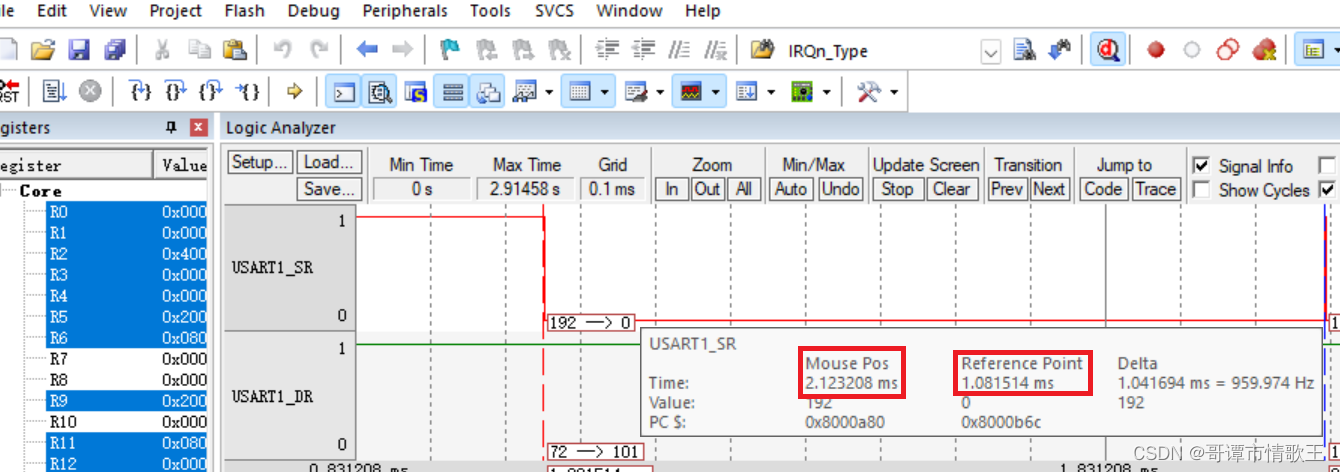
根据观察到的串口输出波形数据可以看到数据位的传输,并且波形的周期与所设定的波特率相符。
四.总结
总之,学习是一件**的事情。


 3515
3515

 被折叠的 条评论
为什么被折叠?
被折叠的 条评论
为什么被折叠?
 到【灌水乐园】发言


