


 本文详细介绍了MPC5748G开发板中STM系统定时器模块的使用,包括时钟源概念、STM模块结构、编程思路和代码实现。通过设置STM定时器控制LED的周期性闪烁,展示了如何利用STM_0的通道0进行1秒定时,并在中断服务函数中更新计数器以实现周期性事件。
前言
本文做一下STM系统定时器模块的笔记。
1 时钟 clock
时钟,是计算机系统的脉搏,也决定着处理器的运行频率。以MPC5748G来说,它有三个内核,分别为2个32位的e200Z4内核和1个32位的e200Z2内核。
其中Z4核的运行频率为160MHz,Z2核则为80MHz。
如果写一个软件延时:
void delay(uint32_t count) {
    for (volatile uint32_t i = 0; i < count; i++) {
        for (volatile uint32_t j = 0; j < 1000; j++) {
            // 简单的循环来模拟延时
        }
    }
}
分别在这三个核中调用该延时函数,循环点亮一个LED灯,会发现Z2核点亮的LED亮灭速度要慢一倍。
MPC5748G一共有五个时钟源:
-
4 个时钟振荡器:
- 8 - 40 MHz 快速外部振荡器 FXOSC
- 16 MHz 快速内部RC振荡器 FIRC
- 32 KHz 慢速内部振荡器 SXOSC
- 128 KHz 慢速内部RC振荡器 SIRC
-
1 个调频锁相环(FMPLL)
- 乘四个时钟振荡器中的一个 :最高 160 MHz。
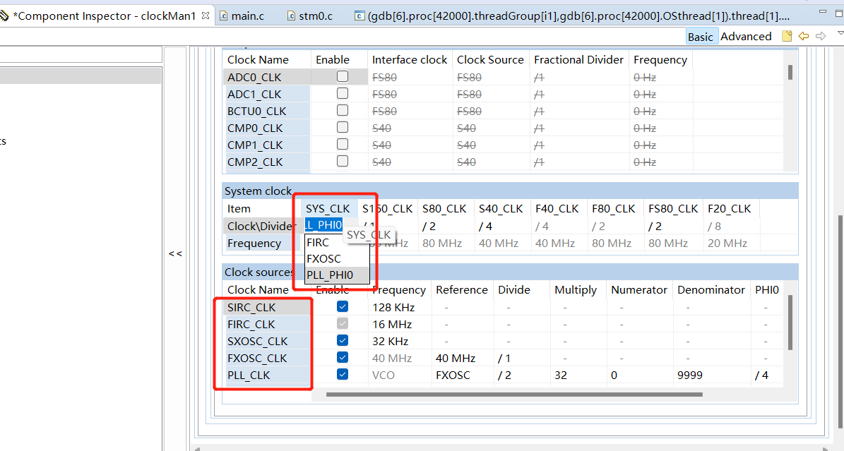
在时钟树里也可以自己选择系统时钟的时钟源:
2 系统定时器模块System Timer Module(STM)
MPC5748G上的定时器模块有很多,包括
- 周期中断定时器(PIT)
- Software Watchdog Timer (SWT)
- Real Time Clock (RTC-API)
- System Timer Module (STM)
作为普通定时器常用的是1个PIT和3个STM,PIT的使用方法参考定时器 timing_pal,本文使用的是系统定时器模块STM。
,
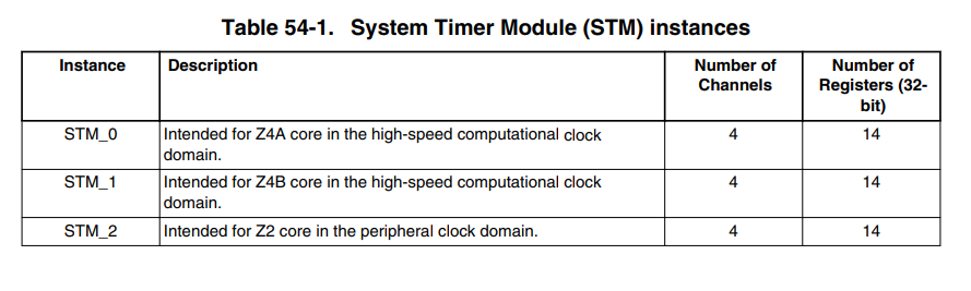
MPC5748G一共有三个STM模块,三个核各有一个。
每个STM包括:
- 一个32位递增计数器
- 四个比较通道
- 每个通道有一个单独的中断源
特点:
•	一个带8位预分频器的32位递增计数器
•	四个32位比较通道
•	每个通道的独立中断源
•	计数器可以在调试模式下停止
•	可编程选择用于定时器操作的系统时钟或FXOSC时钟
3 编程思路
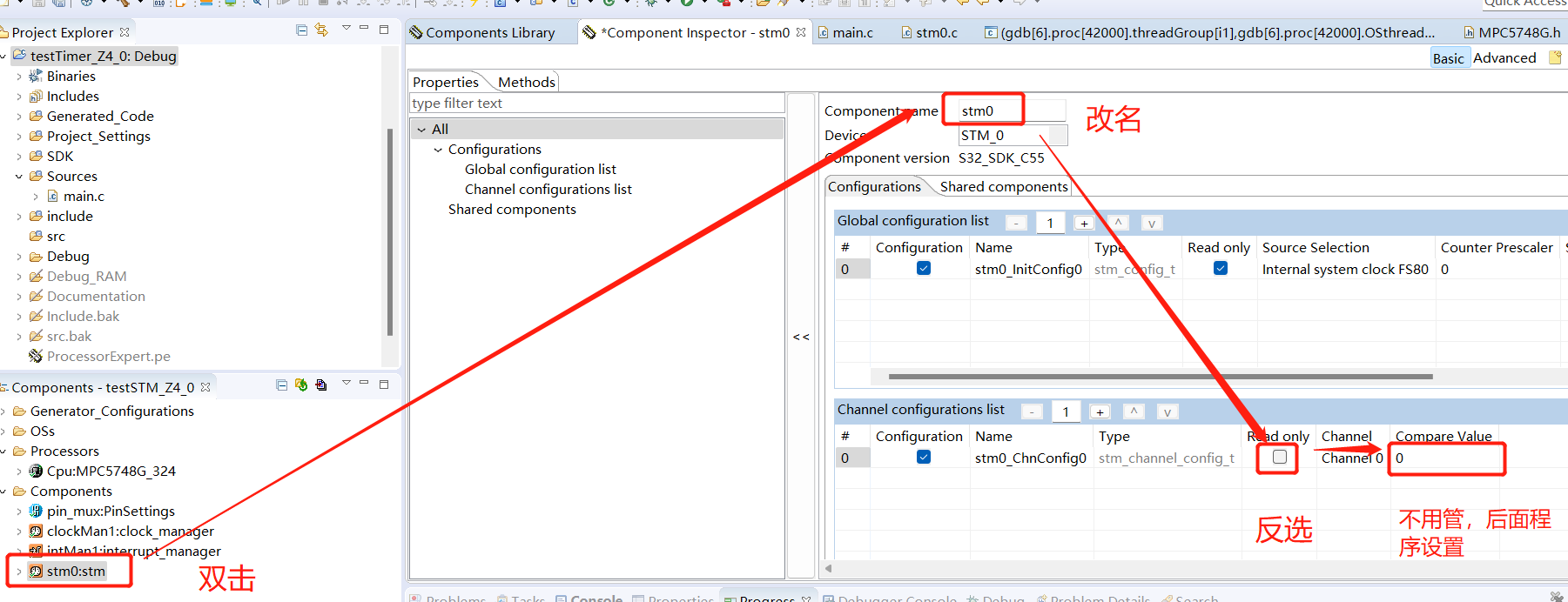
三个STM定时器只用一个STM_0,其中四个通道只用一个0通道,即 STM_0_Ch0。
-
定时器的定时原理为:
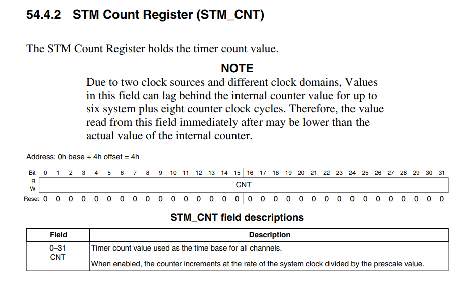
• STM的32位计数寄存器(STM_CNT)自使能以后便开始累加,从0x0000 0000一直累加到0xFFFF FFFF,加满回滚至0x0000 0000,所以其最大值为4294967296。
• 可以设定0通道的32位比较寄存器(STM_CMP0)的值,当 CNT的值 = CMP0的值时,就会触发0通道的中断函数。
了解原理后,就可以设计程序了。
最简单的定时器程序就是控制LED的亮灭了,本程序使用了PA10端口的LED,设置一秒的定时,每过一秒,该LED的值翻转,也就是从亮变灭或者从灭变亮。
4 生成代码
-
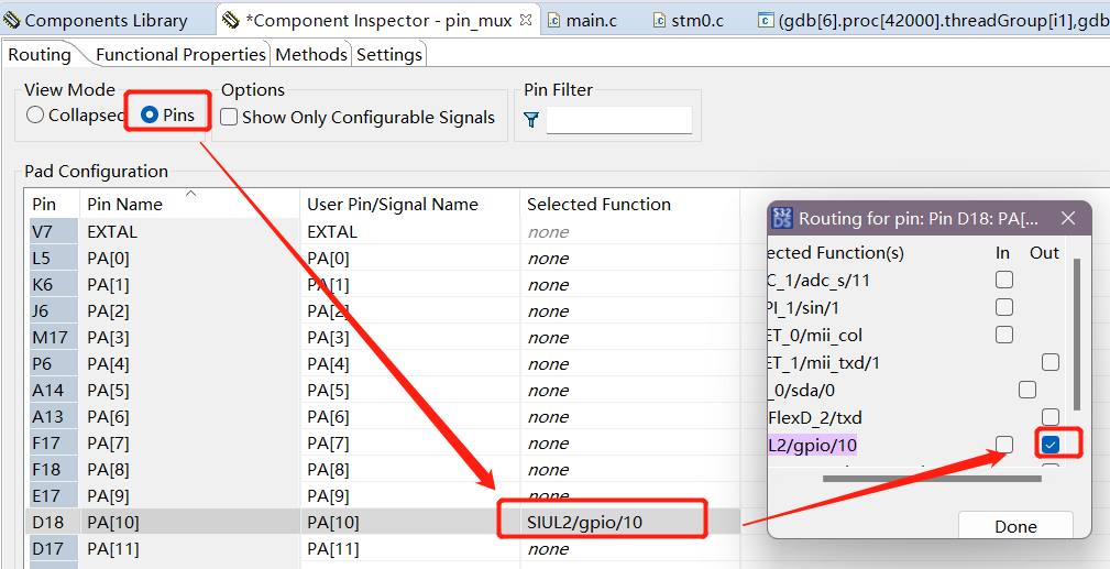
勾选PA[10]为out
-
在模型库中选择stm模块
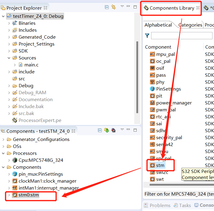
注:加入后可能名为:stm1:stm ,但实际使用的还是STM_0定时器,我把名字改掉了。
-
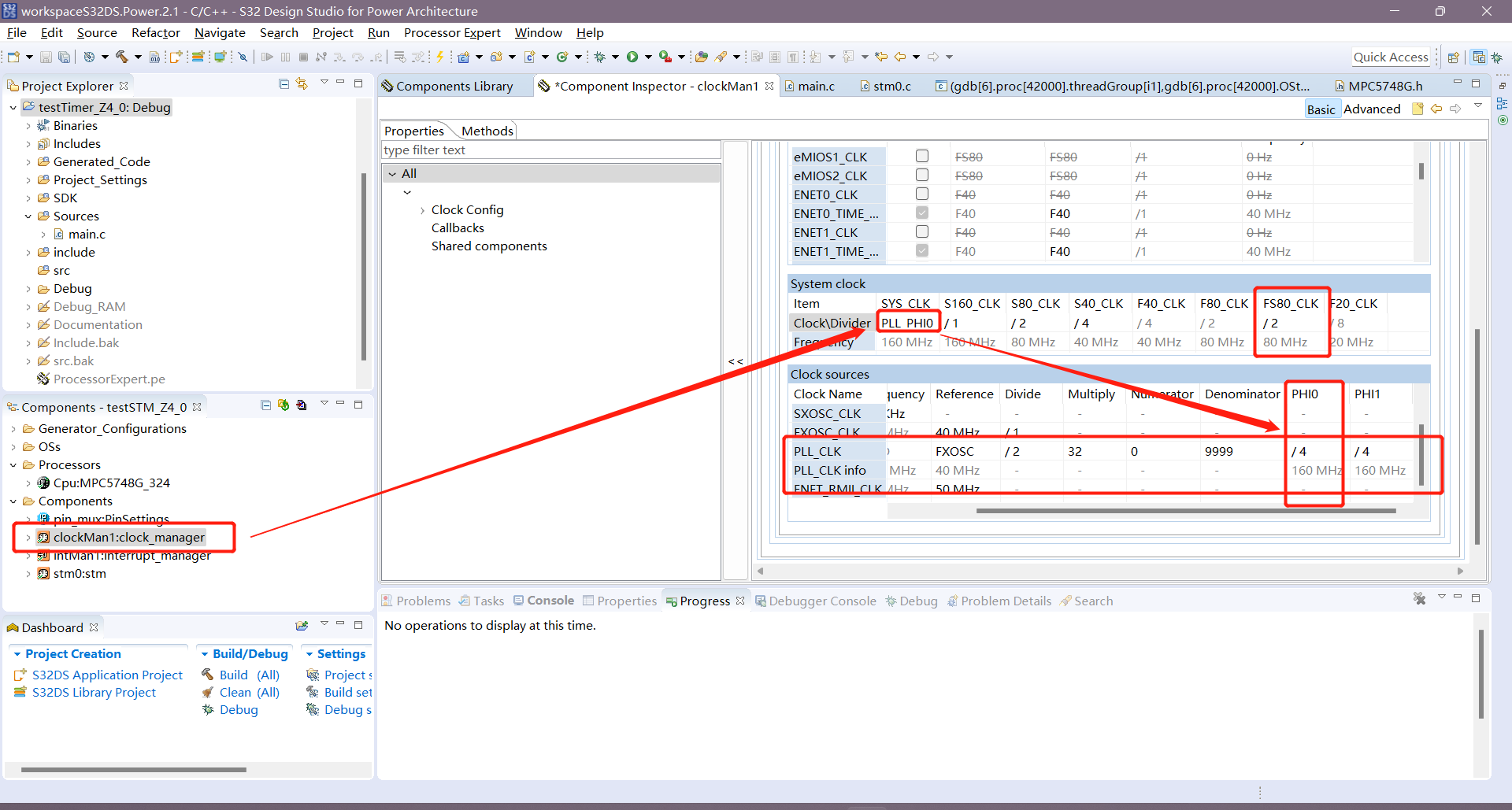
设置STM定时器,可以在Sourece Selection看到时钟源为FS80:
-
看一眼时钟树,看到FS80的频率为80MHz:
-
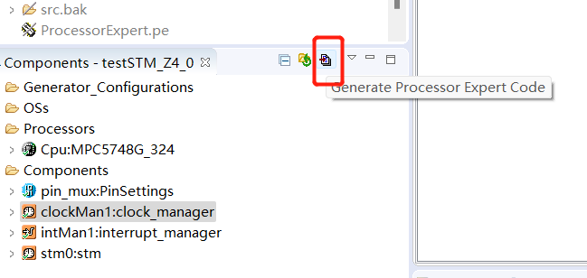
点击生成代码:
5 主函数编写
/* ###################################################################
**     Filename    : main.c
**     Processor   : MPC574xG
**     Abstract    :
**         Main module.
**         This module contains user's application code.
**     Settings    :
**     Contents    :
**         No public methods
**
** ###################################################################*/
/*!
** @file main.c
** @version 01.00
** @brief
**         Main module.
**         This module contains user's application code.
*/
/*!
**  @addtogroup main_module main module documentation
**  @{
*/
/* MODULE main */


/* Including necessary module. Cpu.h contains other modules needed for compiling.*/
#include "Cpu.h"

  volatile int exit_code = 0;
/* User includes (#include below this line is not maintained by Processor Expert) */
#define PORT	PTA
#define LED		10

uint32_t ticks;	/* The number of ticks */

void STM0_Ch0_IRQHandler(void)
{
    /* Clear channel interrupt flag */
    STM_DRV_ClearStatusFlags(INST_STM0, stm0_ChnConfig0.channel);
    /* Toggle Led to check period */
    PINS_DRV_TogglePins(PORT, (1 << LED));
    /* Increase the number of ticks in compare register to create a periodic for next event */
    STM_DRV_IncrementTicks(INST_STM0, stm0_ChnConfig0.channel, ticks);

}
/*!
  \brief The main function for the project.
  \details The startup initialization sequence is the following:
 * - startup asm routine
 * - main()
*/

int main(void)
{
  /* Write your local variable definition here */

  /*** Processor Expert internal initialization. DON'T REMOVE THIS CODE!!! ***/
  #ifdef PEX_RTOS_INIT
    PEX_RTOS_INIT();                   /* Initialization of the selected RTOS. Macro is defined by the RTOS component. */
  #endif
  /*** End of Processor Expert internal initialization.                    ***/

  /* Write your code here */
  /* For example: for(;;) { } */
    /* Initialize clock gate*/
    CLOCK_SYS_Init(g_clockManConfigsArr,   CLOCK_MANAGER_CONFIG_CNT,
                   g_clockManCallbacksArr, CLOCK_MANAGER_CALLBACK_CNT);
    CLOCK_SYS_UpdateConfiguration(0U, CLOCK_MANAGER_POLICY_AGREEMENT);
    /* Initialize and configure pins */
    PINS_DRV_Init(NUM_OF_CONFIGURED_PINS, g_pin_mux_InitConfigArr);
    /* Initialize STM */
    STM_DRV_Init(INST_STM0, &stm0_InitConfig0);
    /* Compute the number of ticks from microseconds */
    STM_DRV_ComputeTicksByUs(INST_STM0,1000000U, &ticks);//以us为单位,计算定时的时间
    /* Initialize channel 0 */
    stm0_ChnConfig0.compareValue = ticks;//设定比较寄存器的值
    STM_DRV_InitChannel(INST_STM0, &stm0_ChnConfig0);//初始化STM_0的0通道
    /* Enable Interrupt for STM0 channel 0 */
    INT_SYS_EnableIRQ(STM0_Ch0_IRQn);//使能STM0 channel0的中断函数,36为STM_0_CIR0[CIF]。
    /* Start running the common timer counter */
    STM_DRV_StartTimer(INST_STM0);//启动STM计数器,将STM控制寄存器STM_CR[TEN]置1。


  /*** Don't write any code pass this line, or it will be deleted during code generation. ***/
  /*** RTOS startup code. Macro PEX_RTOS_START is defined by the RTOS component. DON'T MODIFY THIS CODE!!! ***/
  #ifdef PEX_RTOS_START
    PEX_RTOS_START();                  /* Startup of the selected RTOS. Macro is defined by the RTOS component. */
  #endif
  /*** End of RTOS startup code.  ***/
  /*** Processor Expert end of main routine. DON'T MODIFY THIS CODE!!! ***/
  for(;;) {
    if(exit_code != 0) {
      break;
    }
  }
  return exit_code;
  /*** Processor Expert end of main routine. DON'T WRITE CODE BELOW!!! ***/
} /*** End of main routine. DO NOT MODIFY THIS TEXT!!! ***/

/* END main */
/*!
** @}
*/
/*
** ###################################################################
**
**     This file was created by Processor Expert 10.1 [05.21]
**     for the NXP C55 series of microcontrollers.
**
** ###################################################################
*/
每一行的功能已经注释进去了,具体讲一下ticks这个变量的含义。
- 它首先是一个32位无符号int变量:
uint32_t ticks; /* The number of ticks */
- 在这一行为其赋值:
    /* Compute the number of ticks from microseconds */
    STM_DRV_ComputeTicksByUs(INST_STM0,1000000U, &ticks);//以us为单位,计算定时的时间
其实点开这个函数内部看一看,运算过程已经把1000000这个常数给约掉了。
STM_DRV_ComputeTicksByUs(const uint32_t instance,const uint32_t periodUs,uint32_t * const ticks)

	……省略……

    /* The formula to convert the microsecond value to the number of tick */
    /* ticks = ((periodUs * ClockSrcFreq) / clkPrescaler) / 1000000 */
    tempTicks = (((uint64_t)periodUs * s_stmClockSrcFreq[instance]) / clkPrescaler) / 1000000U;

    ……省略……
所以这一行给ticks赋值为时钟频率:80MHz
ticks = 80,000,000u
- 设定比较寄存器STM_CMP0
stm0_ChnConfig0.compareValue = ticks;//设定比较寄存器的值
这一句把ticks设为STM_CMP0的值,也就是计数寄存器计数到80,000,000时,触发中断,也正好对应了一秒钟。
- 更新STM_CMP0比较器的值
void STM0_Ch0_IRQHandler(void)
{
    /* Clear channel interrupt flag */
    STM_DRV_ClearStatusFlags(INST_STM0, stm0_ChnConfig0.channel);
    /* Toggle Led to check period */
    PINS_DRV_TogglePins(PORT, (1 << LED));
    /* Increase the number of ticks in compare register to create a periodic for next event */
    STM_DRV_IncrementTicks(INST_STM0, stm0_ChnConfig0.channel, ticks);

}
可以看到中断函数中,首先清除了中断标志等待下一次中断,然后翻转了LED的值。
最后又用到了ticks更新比较寄存器STM_CMP0的值,也就是在原来的基础上又加上一个ticks,这样的话等到计数器计数到 2 * ticks 时,便会再次触发该中断函数。
6 运行
烧写程序参考上两篇文章,可以看到LED为1秒的周期进行闪烁。


 1601
1601

 被折叠的 条评论
为什么被折叠?
被折叠的 条评论
为什么被折叠?
 到【灌水乐园】发言


