


矩形网格数据集
矩形网格数据集与结构化点数据集类似,由二维像素或三维体素组成。
之前学习过结构化点和vtkImageData的排列顺序,是一种规则的每个方向上两点之间的spacings是固定的,通常知悉起点orgin、extent和spacing就可以计算出每个点在坐标系中的准确位置;
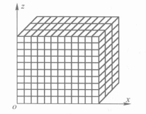
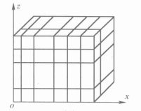
矩形网格数据集中的单元类型要么是像素,要么是体素,知道三个方向上的点的个数就可以计算出所有的点的个数;矩形网格的几何属于半规则结构,虽然不能像结构化点那样可以用一个起始点和三个间隔隐式表达所有点,但也不需要指定所有点的坐标。定义矩形网格的几何只需要知道这三组轴方向上的坐标集合。
vtkRectilinearGrid类
vtkRectilinearGrid类表示了在三个坐标方向上具有可变间距的拓扑规则数据集。
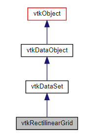
vtkRectilinearGrid类继承自vtkDataSet类,表示了一种几何结构,该结构在三个坐标方向x-y-z上具有可变间距,具有拓扑规则性。
注意:在使用vtkRectilinearGrid类时,必须指定数据的尺寸,并提供三个值数组,指定沿x-y-z轴的坐标。使用三个vtkDataArray对象(一个用于x,一个用于y,一个用于z)指定坐标阵列。如果指定轴方向上的数值与实际数值不同时,就会导致不预期的结果(程序失败)。
创建矩形网格数据集的步骤
0.创建vtkRectilinearGrid类实例rgrid;
1.创建三个vtkDataArray的子类实例(例如vtkFloatArray)来定义数据集的几何,每个对应一个x-y-z坐标轴;
2.使用操作rgrid->SetXCoordinates()、rgrid->SetYCoordinates()、rgrid->SetZCoordinates(),将三个vtkDataArray实例分别设置在对应的坐标轴上;
3.使用操作rgrid->SetDimensions()指定数据集拓扑;
4.创建点属性数据(标量数据)并与数据集关联;
vtkRectilinearGridGeometryFilter类
vtkRectilinearGridGeometryFilter类用于抽取网格中的部分网格数据。
通过指定适当的i-j-k索引,可以提取点、曲线、曲面或“体积”。体积实际上是点的(nmo)区域。扩展数据块规格为零偏移,即下标从0开始。例如:50x50x50直线网格中的第一个k平面由(0,49,0,49,0,0)给出。如果不知道输入数据集的维度值,可以使用一个较大的数字来指定范围(该数字将被适当地收缩)。例如,如果数据集维度为50x50x50,并且我们希望在第五个k平面上创建一个范围,则可以使用范围(0,100,0,100,4,4),程序执行时,100将自动夹紧到49,为(0,50,0,50,4,4)。
 class VTKFILTERSGEOMETRY_EXPORT vtkRectilinearGridGeometryFilter : public vtkPolyDataAlgorithm
 {
 public:
   vtkTypeMacro(vtkRectilinearGridGeometryFilter, vtkPolyDataAlgorithm);
   void PrintSelf(ostream& os, vtkIndent indent) override;
   static vtkRectilinearGridGeometryFilter* New();
   vtkGetVectorMacro(Extent, int, 6);
   void SetExtent(int iMin, int iMax, int jMin, int jMax, int kMin, int kMax);
   void SetExtent(int extent[6]);
 protected:
   vtkRectilinearGridGeometryFilter();
   ~vtkRectilinearGridGeometryFilter() override = default;
   int RequestData(vtkInformation*, vtkInformationVector**, vtkInformationVector*) override;
   int FillInputPortInformation(int port, vtkInformation* info) override;
   int Extent[6];
 private:
   vtkRectilinearGridGeometryFilter(const vtkRectilinearGridGeometryFilter&) = delete;
   void operator=(const vtkRectilinearGridGeometryFilter&) = delete;
 };
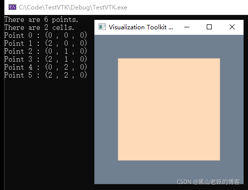
例子1
创建一个矩形网格数据;
int main() {
    vtkNew<vtkNamedColors> colors;

    // Create a grid
    vtkNew<vtkRectilinearGrid> grid;

    grid->SetDimensions(2, 3, 1);

    vtkNew<vtkDoubleArray> xArray;
    xArray->InsertNextValue(0.0);
    xArray->InsertNextValue(2.0);

    vtkNew<vtkDoubleArray> yArray;
    yArray->InsertNextValue(0.0);
    yArray->InsertNextValue(1.0);
    yArray->InsertNextValue(2.0);

    vtkNew<vtkDoubleArray> zArray;
    zArray->InsertNextValue(0.0);

    grid->SetXCoordinates(xArray);
    grid->SetYCoordinates(yArray);
    grid->SetZCoordinates(zArray);

    std::cout << "There are " << grid->GetNumberOfPoints() << " points." << std::endl;
    std::cout << "There are " << grid->GetNumberOfCells() << " cells." << std::endl;

    for (vtkIdType id = 0; id < grid->GetNumberOfPoints(); id++){
        double p[3];
        grid->GetPoint(id, p);
        std::cout << "Point " << id << " : (" << p[0] << " , " << p[1] << " , "
            << p[2] << ")" << std::endl;
    }

    // Create a mapper and actor
    vtkNew<vtkDataSetMapper> mapper;
    mapper->SetInputData(grid);

    vtkNew<vtkActor> actor;
    actor->SetMapper(mapper);
    actor->GetProperty()->SetColor(colors->GetColor3d("PeachPuff").GetData());

    // Visualize
    vtkNew<vtkRenderer> renderer;
    vtkNew<vtkRenderWindow> renderWindow;
    renderWindow->AddRenderer(renderer);
    renderWindow->SetWindowName("RectilinearGrid");

    vtkNew<vtkRenderWindowInteractor> renderWindowInteractor;
    renderWindowInteractor->SetRenderWindow(renderWindow);

    renderer->AddActor(actor);
    renderer->SetBackground(colors->GetColor3d("SlateGray").GetData());

    renderWindow->Render();
    renderWindowInteractor->Start();

    return 0;
}
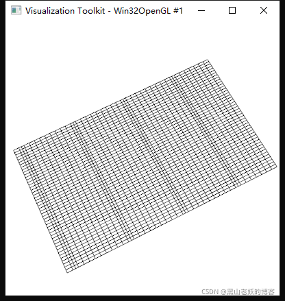
例子2
1.定义三个数组,分别表示沿各个坐标轴上的坐标,数组的长度代表了尺寸值。
2.将数组存储到vtkFloatArray类实例中。
3.创建vtkRectilinearGrid类实例,设置其尺寸并将之前创建的三个实例分配到该实例中。
#include "vtkCellArray.h"
#include "vtkFloatArray.h"
#include "vtkPointData.h"
#include "vtkPoints.h"
#include "vtkPolyData.h"
#include "vtkPolyDataMapper.h"
#include "vtkCamera.h"
#include "vtkActor.h"
#include "vtkRenderer.h"
#include "vtkRenderWindow.h"
#include "vtkRenderWindowInteractor.h"
#include "vtkInteractorStyleImage.h"

#include "vtkAutoInit.h"
VTK_MODULE_INIT(vtkRenderingOpenGL2);
VTK_MODULE_INIT(vtkInteractionStyle);

#include "vtkProperty.h"
#include "vtkRectilinearGrid.h"
#include "vtkRectilinearGridGeometryFilter.h"
int main() {
    static float x[47] = {
           -1.22396, -1.17188, -1.11979, -1.06771, -1.01562, -0.963542,
           -0.911458, -0.859375, -0.807292, -0.755208, -0.703125, -0.651042,
           -0.598958, -0.546875, -0.494792, -0.442708, -0.390625, -0.338542,
           -0.286458, -0.234375, -0.182292, -0.130209, -0.078125, -0.026042,
            0.0260415, 0.078125, 0.130208, 0.182291, 0.234375, 0.286458,
            0.338542, 0.390625, 0.442708, 0.494792, 0.546875, 0.598958,
            0.651042, 0.703125, 0.755208, 0.807292, 0.859375, 0.911458,
            0.963542, 1.01562, 1.06771, 1.11979, 1.17188 };
    static float y[33] = { -1.25, -1.17188, -1.09375, -1.01562, -0.9375, -0.859375,
           -0.78125, -0.703125, -0.625, -0.546875, -0.46875, -0.390625,
           -0.3125, -0.234375, -0.15625, -0.078125, 0, 0.078125,
            0.15625, 0.234375, 0.3125, 0.390625, 0.46875, 0.546875,
            0.625, 0.703125, 0.78125, 0.859375, 0.9375, 1.01562,
            1.09375, 1.17188, 1.25 };
    static float z[44] = { 0, 0.1, 0.2, 0.3, 0.4, 0.5,
           0.6, 0.7, 0.75, 0.8, 0.9, 1,
           1.1, 1.2, 1.3, 1.4, 1.5, 1.6,
           1.7, 1.75, 1.8, 1.9, 2, 2.1,
           2.2, 2.3, 2.4, 2.5, 2.6, 2.7,
           2.75, 2.8, 2.9, 3, 3.1, 3.2,
           3.3, 3.4, 3.5, 3.6, 3.7, 3.75,
           3.8, 3.9 };

    // 定义三组分别沿x、y、z轴上的坐标。
    vtkNew<vtkFloatArray> xCoords;
    for (int i = 0; i < 47; i++) xCoords->InsertNextValue(x[i]);
    vtkNew<vtkFloatArray> yCoords;
    for (int i = 0; i < 33; i++) yCoords->InsertNextValue(y[i]);
    vtkNew<vtkFloatArray> zCoords;
    for (int i = 0; i < 44; i++) zCoords->InsertNextValue(z[i]);

    // 将坐标分配给矩形网格。确保每根轴上的坐标数量与方法
    // SetDimensions()中设置的相应尺寸相等。
    vtkNew<vtkRectilinearGrid> rgrid;
    rgrid->SetDimensions(47, 33, 44);
    rgrid->SetXCoordinates(xCoords);
    rgrid->SetYCoordinates(yCoords);
    rgrid->SetZCoordinates(zCoords);

    // 从网格中抽取一个面来看看我们获得的结果。
    vtkNew<vtkRectilinearGridGeometryFilter> plane;
    plane->SetInputData(rgrid);
    plane->SetExtent(0, 46, 16, 16, 0, 43);

    vtkPolyDataMapper* rgridMapper = vtkPolyDataMapper::New();
    rgridMapper->SetInputConnection(plane->GetOutputPort());

    vtkNew<vtkActor> wireActor;
    wireActor->SetMapper(rgridMapper);
    wireActor->GetProperty()->SetRepresentationToWireframe();
    wireActor->GetProperty()->SetColor(0, 0, 0);

    vtkNew<vtkRenderer> renderer;
    vtkNew<vtkRenderWindow> renWin;
    renWin->AddRenderer(renderer);
    vtkNew<vtkRenderWindowInteractor> iren;
    iren->SetRenderWindow(renWin);

    renderer->AddActor(wireActor);
    renderer->SetBackground(1, 1, 1);
    renderer->ResetCamera();
    renderer->GetActiveCamera()->Elevation(60.0);
    renderer->GetActiveCamera()->Azimuth(30.0);
    renderer->GetActiveCamera()->Zoom(1.0);

    renWin->SetSize(400, 400);

    renWin->Render();
    iren->Start();

    return 0;
}
参考资料
1.《医学图像编程技术》


 124
124

 被折叠的 条评论
为什么被折叠?
被折叠的 条评论
为什么被折叠?
 到【灌水乐园】发言


