


文章目录
1.创建工作空间
在主文件夹下新建一个文件夹, 命名为catkin_urdf
进入该文件夹, 再创建一个src文件夹, 并在src文件夹里运行ROS的工作空间初始化命令catkin_init_workspace
回到catkin_urdf文件夹, 使用catkin_make编译整个工作空间
最后, 打开终端, 输入echo "source ~/catkin_urdf/devel/setup.bash" >> ~/.bashrc, 设置环境变量
2.创建功能包
在catkin_urdf下的src里运行
catkin_create_pkg mrobot_description urdf xacro
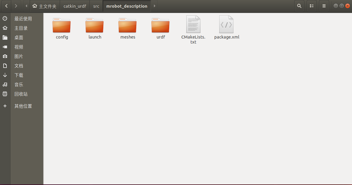
进入mrobot_description文件夹, 新建urdf、meshes、launch、config四个文件夹, 用来存放文件, 效果如图所示:
3.urdf文件
在mrobot_description包的urdf文件夹下新建三个xacro文件, 其中的内容如下:
注意: 代码中不要含有中文的注释
mrobot_body.urdf.xacro
<?xml version="1.0" ?>
<robot name="mrobot_body" xmlns:xacro="http://www.ros.org/wiki/xacro">

    <xacro:property name="M_PI" value="3.14159"/>
    <xacro:property name="wheel_radius" value="0.033"/>
    <xacro:property name="wheel_length" value="0.017"/>
    <xacro:property name="base_radius" value="0.13"/>
    <xacro:property name="base_length" value="0.005"/>
    <xacro:property name="motor_radius" value="0.02"/>
    <xacro:property name="motor_length" value="0.08"/>
    <xacro:property name="motor_x" value="0.055"/>
    <xacro:property name="motor_y" value="0.075"/>
    <xacro:property name="plate_height" value="0.07"/>
    <xacro:property name="standoff_x" value="0.12"/>
    <xacro:property name="standoff_y" value="0.1"/>

    <!-- Defining the colors used in this robot -->
    <material name="yellow">
        <color rgba="1 0.4 0 1"/>
    </material>
    <material name="black">
        <color rgba="0 0 0 0.95"/>
    </material>
    <material name="gray">
        <color rgba="0.75 0.75 0.75 1"/>
    </material>
    <material name="white">
        <color rgba="1 1 1 0.9"/>
    </material>


    <link name="base_link">
        <visual>
            <origin xyz="0 0 0" rpy="0 0 0"/>
            <geometry>
                <cylinder length="${base_length}" radius="${base_radius}"/>
            </geometry>
            <material name="yellow"/>
        </visual>

        <inertial>
            <mass value="2"/>
            <origin xyz="0 0 0.0"/>
            <inertia ixx="0.01" ixy="0" ixz="0"
                     iyy="0.01" iyz="0"
                     izz="0.5"/>
        </inertial>

        <collision>
            <origin xyz="0 0 0" rpy="0 0 0"/>
            <geometry>
                <cylinder length="${base_length}" radius="${base_radius}"/>
            </geometry>
        </collision>
    </link>

    <joint name="base_left_motor_joint" type="fixed">
        <origin xyz="${-1 * motor_x} ${motor_y} 0" rpy="0 0 0"/>
        <parent link="base_link"/>
        <child link="left_motor"/>
    </joint>

    <link name="left_motor">
        <visual>
            <origin xyz="0 0 0" rpy="${M_PI / 2} 0 0"/>
            <geometry>
                <cylinder radius="${motor_radius}" length="${motor_length}"/>
            </geometry>
            <material name="gray"/>
        </visual>

        <inertial>
            <origin xyz="0.0 0 0"/>
            <mass value="0.1"/>
            <inertia ixx="0.001" ixy="0.0" ixz="0.0"
                     iyy="0.001" iyz="0.0"
                     izz="0.001"/>
        </inertial>

        <collision>
            <origin xyz="0 0 0" rpy="${M_PI/2} 0 0"/>
            <geometry>
                <cylinder radius="${motor_radius}" length="${motor_length}"/>
            </geometry>
        </collision>
    </link>

    <joint name="left_wheel_joint" type="continuous">
        <origin xyz="0 ${(motor_length + wheel_length) / 2} 0" rpy="0 0 0"/>
        <parent link="left_motor"/>
        <child link="left_wheel_link"/>
        <axis xyz="0 1 0"/>
    </joint>

    <link name="left_wheel_link">
        <visual>
            <origin xyz="0 0 0" rpy="${M_PI / 2} 0 0"/>
            <geometry>
                <cylinder radius="${wheel_radius}" length="${wheel_length}"/>
            </geometry>
            <material name="white"/>
        </visual>

        <inertial>
            <origin xyz="0 0 0"/>
            <mass value="0.01" />
            <inertia ixx="0.001" ixy="0.0" ixz="0.0"
                     iyy="0.001" iyz="0.0"
                     izz="0.001" />
        </inertial>

        <collision>
            <origin xyz="0 0 0" rpy="${M_PI/2} 0 0" />
            <geometry>
                <cylinder radius="${wheel_radius}" length = "${wheel_length}"/>
            </geometry>
        </collision>
    </link>

    <joint name="base_right_motor_joint" type="fixed">
        <origin xyz="${-1 * motor_x} ${-1 * motor_y} 0" rpy="0 0 0"/>
        <parent link="base_link"/>
        <child link="right_motor"/>
    </joint>

    <link name="right_motor">
        <visual>
            <origin xyz="0 0 0" rpy="${M_PI / 2} 0 0"/>
            <geometry>
                <cylinder radius="${motor_radius}" length="${motor_length}"/>
            </geometry>
            <material name="gray"/>
        </visual>

        <inertial>
            <origin xyz="0.0 0 0"/>
            <mass value="0.1" />
            <inertia ixx="0.001" ixy="0.0" ixz="0.0"
                     iyy="0.001" iyz="0.0"
                     izz="0.001" />
        </inertial>

        <collision>
            <origin xyz="0 0 0" rpy="${M_PI/2} 0 0" />
            <geometry>
                <cylinder radius="${motor_radius}" length = "${motor_length}"/>
            </geometry>
        </collision>
    </link>

    <joint name="right_wheel_joint" type="continuous">
        <origin xyz="0 ${ (wheel_length + motor_length) / (-2) } 0" rpy="0 0 0"/>
        <parent link="right_motor"/>
        <child link="right_wheel_link"/>
        <axis xyz="0 1 0"/>
    </joint>

    <link name="right_wheel_link">
        <visual>
            <origin xyz="0 0 0" rpy="${M_PI / 2} 0 0"/>
            <geometry>
                <cylinder radius="${wheel_radius}" length="${wheel_length}"/>
            </geometry>
            <material name="white"/>
        </visual>

        <inertial>
            <origin xyz="0 0 0"/>
            <mass value="0.01" />
            <inertia ixx="0.001" ixy="0.0" ixz="0.0"
                     iyy="0.001" iyz="0.0"
                     izz="0.001" />
        </inertial>

        <collision>
            <origin xyz="0 0 0" rpy="${M_PI/2} 0 0" />
            <geometry>
                <cylinder radius="${wheel_radius}" length = "${wheel_length}"/>
            </geometry>
        </collision>
    </link>

    <joint name="front_caster_joint" type="fixed">
        <origin xyz="${base_radius - wheel_radius / 2} 0 -${wheel_radius / 2}" rpy="0 0 0"/>
        <parent link="base_link"/>
        <child link="front_caster_link"/>
    </joint>

    <link name="front_caster_link">
        <visual>
            <origin xyz="0 0 0" rpy="${M_PI / 2} 0 0"/>
            <geometry>
                <sphere radius="${wheel_radius / 2}"/>
            </geometry>
            <material name="black"/>
        </visual>

        <inertial>
            <origin xyz="0 0 0"/>
            <mass value="0.001"/>
            <inertia ixx="0.0001" ixy="0.0" ixz="0.0"
                     iyy="0.0001" iyz="0.0"
                     izz="0.0001"/>
        </inertial>

        <collision>
            <origin xyz="0 0 0.01" rpy="${M_PI/2} 0 0"/>
            <geometry>
                <sphere radius="${wheel_radius/2}"/>
            </geometry>
        </collision>
    </link>

    <!--  the supportColumn -->
    <xacro:macro name="support_column" params="parent number x_loc y_loc z_loc">
        <joint name="support_column_${number}_joint" type="fixed">
            <origin xyz="${x_loc} ${y_loc} ${z_loc}" rpy="0 0 0"/>
            <parent link="${parent}"/>
            <child link="support_column_${number}_link"/>
        </joint>

        <link name="support_column_${number}_link">
            <visual>
                <origin xyz="0 0 0" rpy="0 0 0"/>
                <geometry>
                    <box size="0.01 0.01 0.07"/>
                </geometry>
                <material name="black"/>
            </visual>

            <interial>
                <mass value="0.001"/>
                <origin xyz="0 0 0"/>
                <interia ixx="0.0001" ixy="0" ixz="0"
                         iyy="0.0001" iyz="0"
                         izz="0.0001"/>
            </interial>

            <collision>
                <origin xyz="0 0 0" rpy="0 0 0"/>
                <geometry>
                    <box size="0.01 0.01 0.07"/>
                </geometry>
            </collision>
        </link>

    </xacro:macro>


    <!-- the supportPlate -->
    <xacro:macro name="support_plate" params="parent number height">
        <joint name="support_plate_${number}_joint" type="fixed">
            <origin xyz="0 0 ${height}" rpy="0 0 0"/>
            <parent link="${parent}"/>
            <child link="support_plate_${number}_link"/>
        </joint>

        <link name="support_plate_${number}_link">
            <visual>
                <origin xyz="0 0 0" rpy="0 0 0"/>
                <geometry>
                    <cylinder length="${base_length}" radius="${base_radius}"/>
                </geometry>
                <material name="yellow"/>
            </visual>

            <inertial>
                <mass value="2"/>
                <origin xyz="0 0 0.0"/>
                <inertia ixx="0.01" ixy="0" ixz="0"
                         iyy="0.01" iyz="0"
                         izz="0.5"/>
            </inertial>

            <collision>
                <origin xyz="0 0 0" rpy="0 0 0"/>
                <geometry>
                    <cylinder length="${base_length}" radius="${base_radius}"/>
                </geometry>
            </collision>
        </link>

    </xacro:macro>


    <!-- create 4 supportColumns (1) -->
    <support_column parent="base_link" number="1" x_loc="-${standoff_x / 2 + 0.03}" y_loc="-${standoff_y - 0.03}"
                    z_loc="${plate_height / 2}"/>
    <support_column parent="base_link" number="2" x_loc="-${standoff_x / 2 + 0.03}" y_loc="${standoff_y - 0.03}"
                    z_loc="${plate_height / 2}"/>
    <support_column parent="base_link" number="3" x_loc="${standoff_x / 2}" y_loc="-${standoff_y}"
                    z_loc="${plate_height / 2}"/>
    <support_column parent="base_link" number="4" x_loc="${standoff_x / 2}" y_loc="${standoff_y}"
                    z_loc="${plate_height / 2}"/>

    <!-- create 4 supportColumns (2) -->
    <support_column parent="base_link" number="5" x_loc="-${standoff_x / 2 + 0.03}" y_loc="-${standoff_y - 0.03}"
                    z_loc="${1.5 * plate_height + base_length}"/>
    <support_column parent="base_link" number="6" x_loc="-${standoff_x / 2 + 0.03}" y_loc="${standoff_y - 0.03}"
                    z_loc="${1.5 * plate_height + base_length}"/>
    <support_column parent="base_link" number="7" x_loc="${standoff_x / 2}" y_loc="-${standoff_y}"
                    z_loc="${1.5 * plate_height + base_length}"/>
    <support_column parent="base_link" number="8" x_loc="${standoff_x / 2}" y_loc="${standoff_y}"
                    z_loc="${1.5 * plate_height + base_length}"/>

    <!-- create 2 SupportPlates -->
    <support_plate parent="base_link" number="1" height="${plate_height + base_length}"/>
    <support_plate parent="base_link" number="2" height="${2 * plate_height + 1.5 * base_length}"/>

</robot>
rplidar.xacro
<?xml version="1.0" ?>
<robot name="laser" xmlns:xacro="http://www.ros.org/wiki/xacro">

    <xacro:macro name="rplidar" params="prefix:=laser">
        <link name="${prefix}_link">
            <visual>
                <origin xyz="0 0 0" rpy="0 0 0"/>
                <geometry>
                    <cylinder length="0.05" radius="0.05" />
                </geometry>
                <material name="black"/>
            </visual>

            <inertial>
                <mass value="0.1"/>
                <origin xyz="0 0 0"/>
                <inertia ixx="0.01" ixy="0" ixz="0"
                         iyy="0.01" iyz="0"
                         izz="0.01"/>
            </inertial>

            <collision>
                <origin xyz="0 0 0" rpy="0 0 0"/>
                <geometry>
                    <cylinder length="0.05" radius="0.05"/>
                </geometry>
            </collision>

        </link>

    </xacro:macro>
</robot>
mrobot_with_rplidar.urdf.xacro
<?xml version="1.0" ?>
<robot name="mrobot" xmlns:xacro="http://www.ros.org/wiki/xacro" >

    <xacro:include filename="$(find mrobot_description)/urdf/mrobot_body.urdf.xacro"/>
    <xacro:include filename="$(find mrobot_description)/urdf/rplidar.xacro"/>

    <xacro:property name="rplidar_offset_x" value="0"/>
    <xacro:property name="rplidar_offset_y" value="0"/>
    <xacro:property name="rplidar_offset_z" value="0.028"/>

    <mrobot_body/>

    <!-- rplidar -->
    <joint name="rplidar_joint" type="fixed">
        <origin xyz="${rplidar_offset_x} ${rplidar_offset_y} ${rplidar_offset_z}" rpy="0 0 0"/>
        <parent link="support_plate_2_link"/>
        <child link="laser_link"/>
    </joint>

    <xacro:rplidar prefix="laser"/>

</robot>
4.launch文件
在mrobot_description包的launch文件夹下新建一个launch文件, 命名为
with_rplidar.launch, 其中的内容如下:
<launch>
    <param name="use_gui" value="true"/>

    <node name="joint_state_publisher_gui" pkg="joint_state_publisher_gui" type="joint_state_publisher_gui" />
    <node name="robot_state_publisher" pkg="robot_state_publisher" type="robot_state_publisher" />
    <node name="rviz" pkg="rviz" type="rviz" args="-d $(find mrobot_description)/config/mrobot_urdf.rviz" required="true" />

	<!--   xacro ===> urdf       rplidar     -->
	<arg name="model" default="$(find xacro)/xacro --inorder '$(find mrobot_description)/urdf/mrobot_with_rplidar.urdf.xacro' "/>
	<param name="robot_description" command="$(arg model)" />

 </launch>
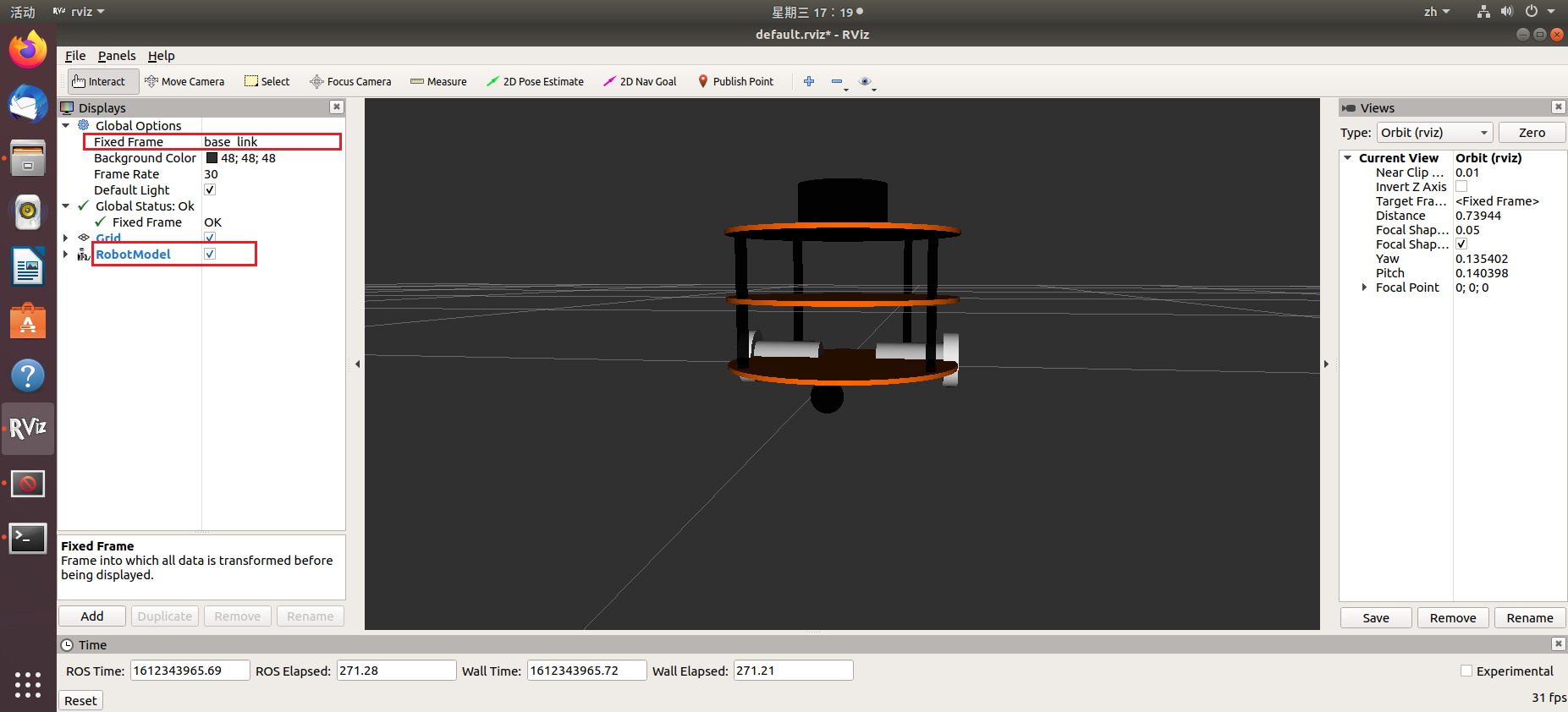
5.运行rviz
直接在终端输入下面的命令, 并在rviz软件中, 将Fixed Frame设置为base_link, 然后添加RobotModel, 即可在rviz中看到安装有激光雷达的机器人模型
roslaunch mrobot_description with_rplidar.launch


 1902
1902


 被折叠的 条评论
为什么被折叠?
被折叠的 条评论
为什么被折叠?
 到【灌水乐园】发言


