


1.思路
利用2输入端与非门元件,设计4输入端的与非与非电路
1.1

1.2
1.3
2.实现过程
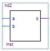
2.1 设计2输入端与非门
library ieee;
use ieee.std_logic_1164.all;

entity nd2 is
    port(a,b : in std_logic;
	      c : out std_logic);
end nd2;

architecture nd2bahave of nd2 is
  begin
	 c <= a nand b;
  end nd2bahave;
2.2 将设计的元件声明装入my_pkg程序包中(完成元件的“封装”)
library ieee;
use ieee.std_logic_1164.all;

package my_pkg is
  component nd2                 --元件声明
    port (a,b : in std_logic;
	       c : out std_logic);
  end component;
end my_pkg;
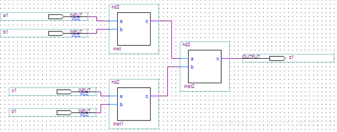
2.3 用原件例化产生电路(完成电路板上的元件“插座”的定义)
library ieee;
use ieee.std_logic_1164.all;

entity ord41 is
port (a1,b1,c1,d1 : in std_logic;
      z1 : out std_logic);
end ord41;

architecture ord41behave of ord41 is  --元件例化
  signal x,y : std_logic;
  component nd2                       --元件声明
    port (a,b : in std_logic;
	       c : out std_logic);
  end component;

  begin
  u1 : nd2 port map (a1,b1,x);       --位置关联方式:表达式(信号)必须与元件声明语句中的端口顺序一致
  u2 : nd2 port map (a => c1,        --名字关联方式
  b => d1,c => y);
  u3 : nd2 port map (x,y,c => z1);   --混合关联方式
end ord41behave;
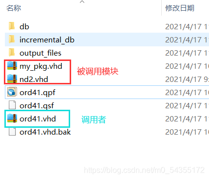
3.注意:被调用的模块,要将其vhd文件放入调用者的文件中


 764
764

 被折叠的 条评论
为什么被折叠?
被折叠的 条评论
为什么被折叠?
 到【灌水乐园】发言


