


• Introduction on the Electrostatic Solver
– This workshop introduces the Electro Static solver based on some simple examples. This solver is meant to solve the static electric field without current flowing in conductors (conductors are in electrostatic equilibrium). The conductors are considered perfect such that there is no electric field inside conductors.
Electrostatic求解器用于解决静电场而无需电流在导体中流动的问题,导体处于静电平衡状态。在该解算器重,导体认为是理想的,因此认为导体内部没有电场。
Example1: Cylindrical Capacitor in RZ
• In this example, we will determine the electric field distribution of coaxial cable based on the potential (or the charges) that are applied on each conductor. Coaxial cable will be solved with RZ representation
分析同轴电缆的电场分布,同轴电缆通过RZ坐标轴进行建模。
Step01: 建立工程文档,配置工程
• Create Design
– Select the menu item Project Insert Maxwell 2D Design,
• Set Solution Type
– Select the menu item Maxwell 2D Solution Type
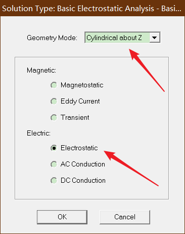
– Solution Type Window:
1. Geometry Mode: Cylindrical about Z
2. Choose Electric > Electrostatic
3. Click the OK button
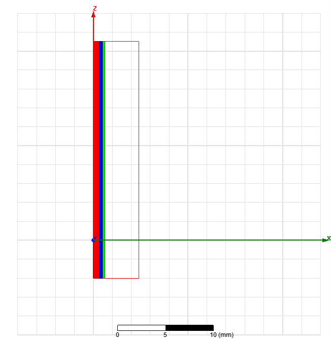
Step02:Create Model 创建模型
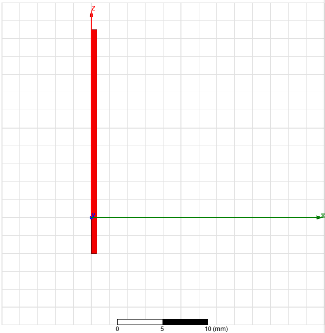
• Create object Inner
– Select the menu item Draw Rectangle
1. Using the coordinate entry fields, enter the position of rectangle
– X: 0, Y: 0, Z: -4, Press the Enter key
2. Using the coordinate entry fields, enter the opposite corner
– dX: 0.6, dY: 0, dZ: 25, Press the Enter key
– Change the name of resulting sheet to Inner and color to Light Red
– Change the material of the sheet to Copper
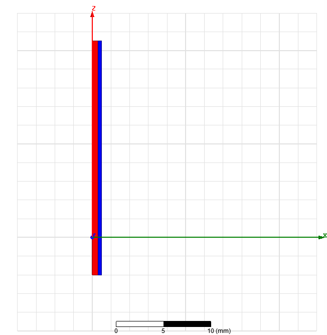
• Create Air Gap
– Select the menu item Draw Rectangle
1. Using the coordinate entry fields, enter the position of rectangle
– X: 0.6, Y: 0, Z: -4, Press the Enter key
2. Using the coordinate entry fields, enter the opposite corner
– dX: 0.4, dY: 0, dZ: 25, Press the Enter key
– Change the name of resulting sheet to Air and color to Light Blue
– Change the material of the sheet to air
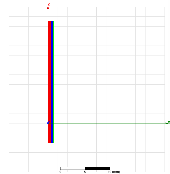
• Create object outer
– Select the menu item Draw Rectangle
1. Using the coordinate entry fields, enter the position of rectangle
– X: 1, Y: 0, Z: -4, Press the Enter key
2. Using the coordinate entry fields, enter the opposite corner
– dX: 0.2, dY: 0, dZ: 25, Press the Enter key
– Change the name of resulting sheet to Outer and color to Light Green
– Change the material of the sheet to Copper
• Create Simulation Region
– Select the menu item Draw Region
– In Region window,
1. Pad individual directions: Checked
2. Padding Type: Percentage Offset
– +R = 300
– Specify rest to 0
3. Press OK
Step03:Assign Excitations:分配激励
• Assign Excitation to object Inner
– Select the sheet Inner from the history tree
– Select the menu item Maxwell 2D Excitations Assign Voltage
 最低0.47元/天 解锁文章


 4865
4865

 被折叠的 条评论
为什么被折叠?
被折叠的 条评论
为什么被折叠?
 到【灌水乐园】发言


