


在fpga中通过使用nios-ii软核实现流水灯亮灭
Qsys 系统设计
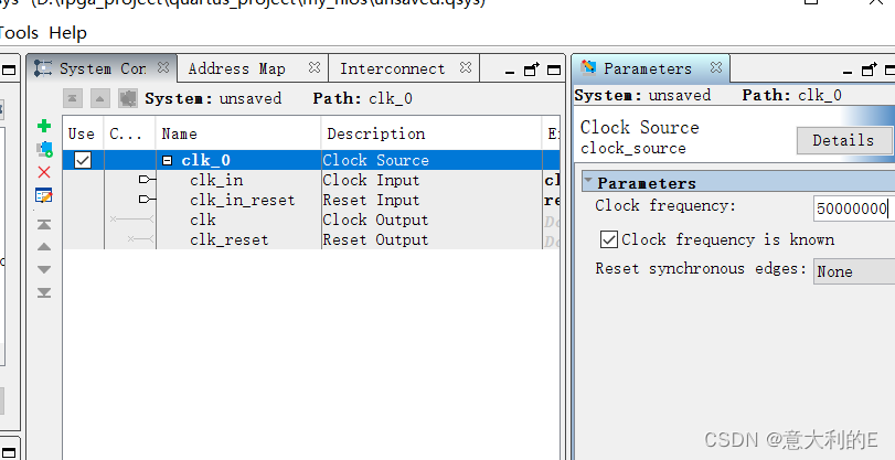
在新建quartus工程里选择platform designer, 建立并生成一个简单的基于 Nios II 的硬件系统
设置clk_0的频率为50MHZ
从library里面添加Nios II Processor到系统,在 Nios Core 栏中选择 Nios II/f 选项(其他内容不变),并在项目中重新命名为"cpu",并在电路图中连接cpu clk与clk0的clk,cpu
reset 与clk0_reset
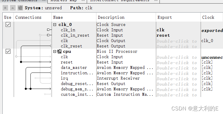
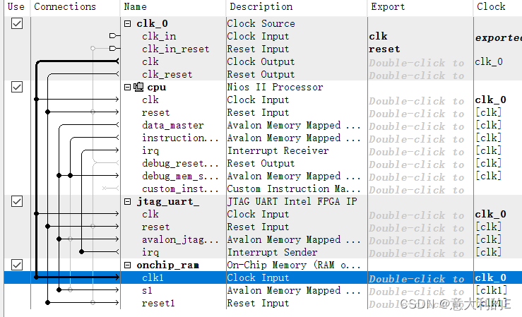
从library添加在 JTAG UART(默认设置),重命名为jtag_uart,clk、reset按同样位置连接,avalon_jtag连接cpu data_master并在IRQ连接IRQ31.

从library添加On-Chip Memory Intel FPGA,在”Size”栏中的”Total memory size”窗口中输入 40960,最后更名为onchip_ram
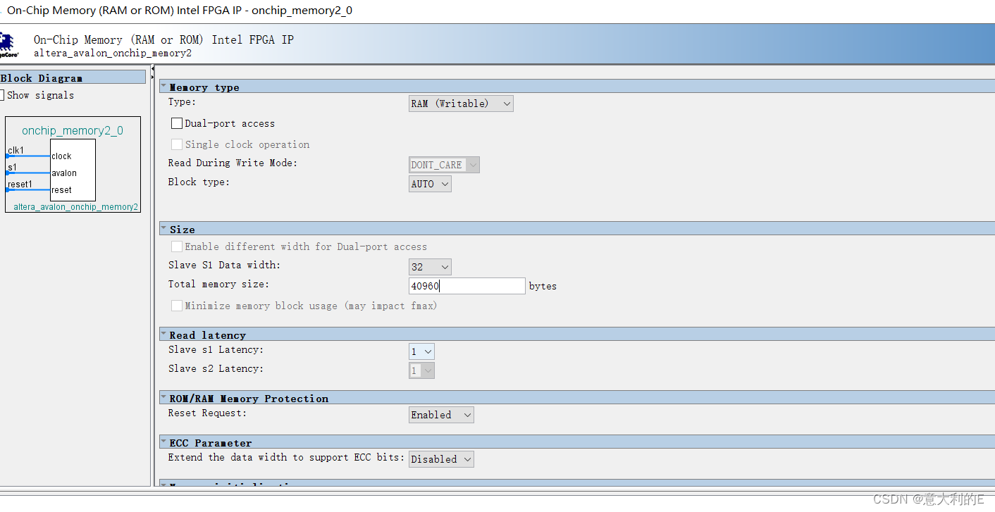
端口按之前同样的位置接线即可:
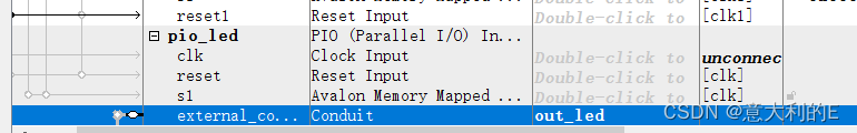
搜索添加PIO
设置如下

改名为 pio_led,在external_connection的export栏双击,并命名为 out_led。
在library搜索sys,添加system id peripherial,保持默认,改名为 sysid.
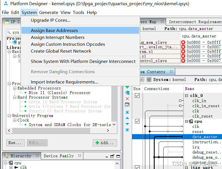
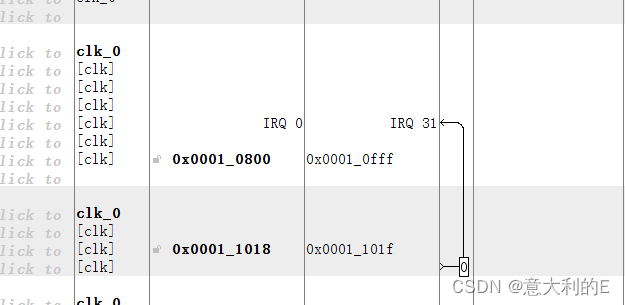
选择system ,assign base addesses
在IRQ标签栏下选择Avalon_itag_slave和IRQ的连接点就会jtag_uart核添加一个值为0的中断号.
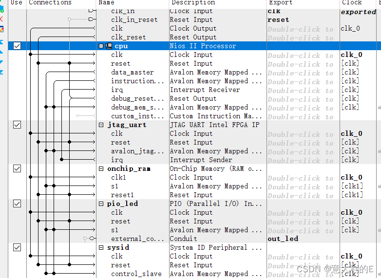
最后连线如下:
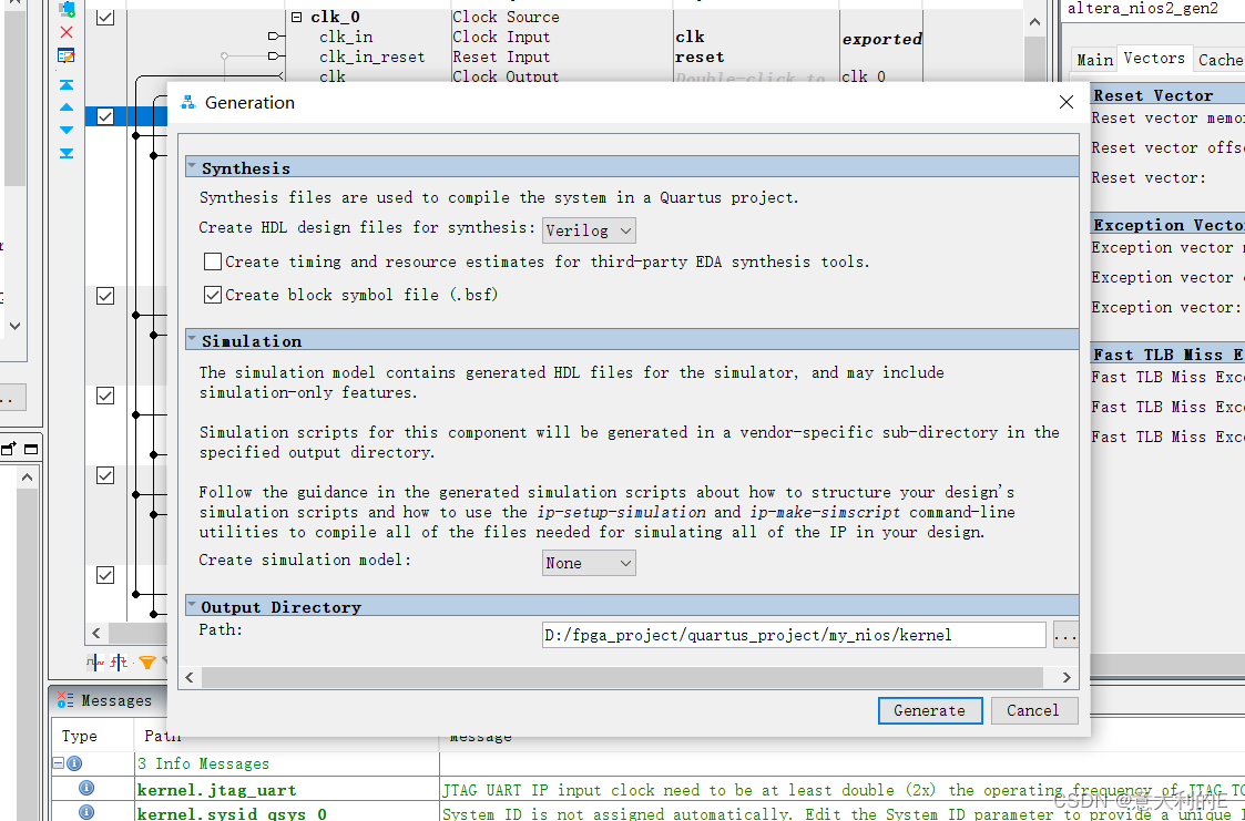
从 System Contents 标签栏双击建立好的 cpu 进入 Nios II Processor 的配置界面,配置 Reset Vector 和 Exception Vector 为 ”onchip_ram.s1,点击 Finish
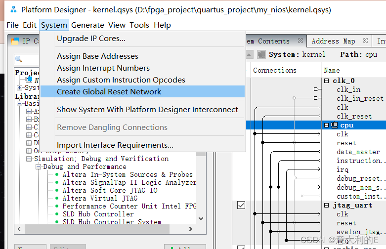
点击 Qsys 主界面菜单栏中的 System 下的Create Global Reset Network
Generation HDL 标签栏中 Generate
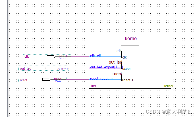
在原理图中添加生成的bsf文件。点击 Assignments-Settings,添加 kernel.qip 文件。
管脚连接如下:
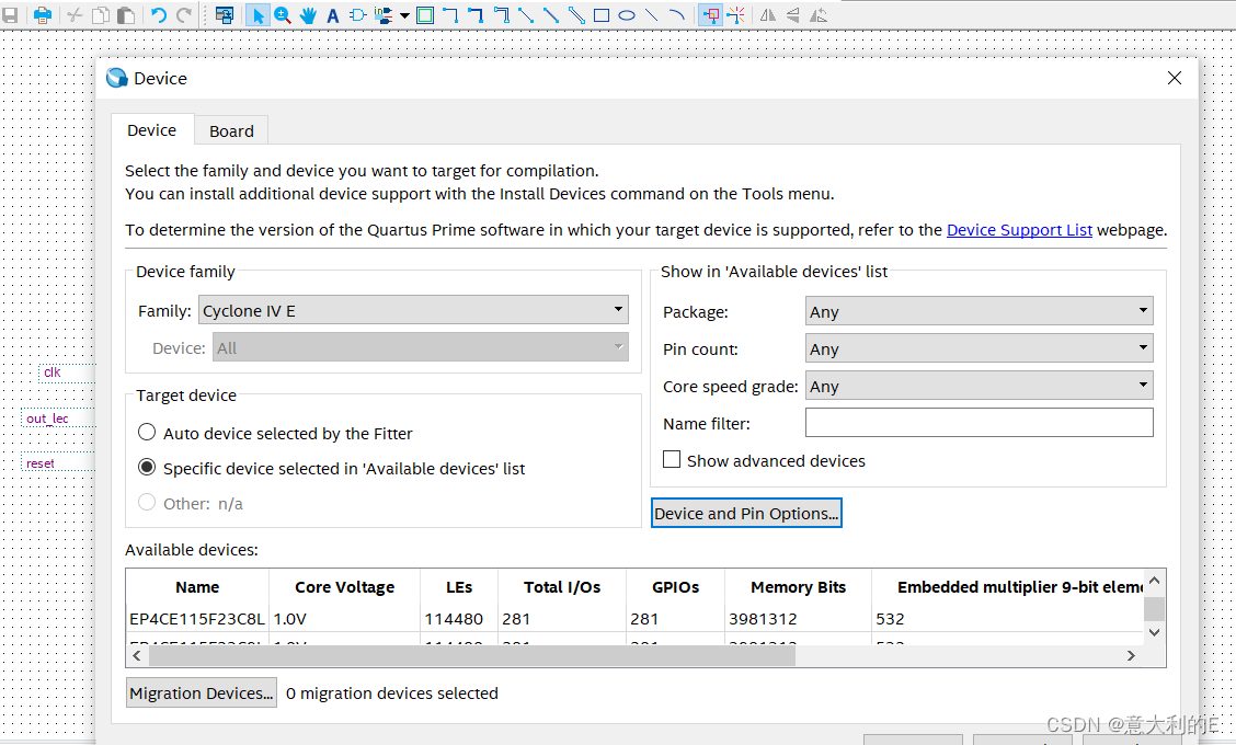
选择device pin options
unused pins设置如下:
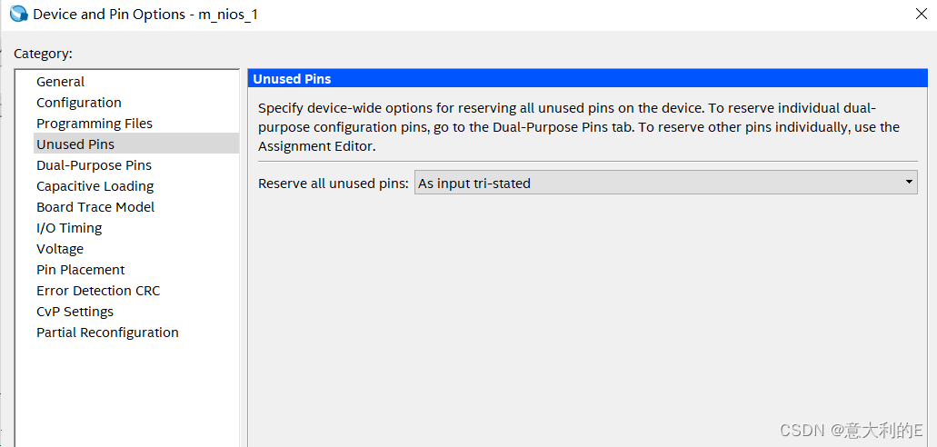
随后编译通过

tcl分配引脚:
package require ::quartus::project

set_location_assignment PIN_Y2 -to clk_clk
set_location_assignment PIN_G17 -to out_led_export[7]
set_location_assignment PIN_J17 -to out_led_export[6]
set_location_assignment PIN_H19 -to out_led_export[5]
set_location_assignment PIN_J19 -to out_led_export[4]
set_location_assignment PIN_E18 -to out_led_export[3]
set_location_assignment PIN_F18 -to out_led_export[2]
set_location_assignment PIN_F21 -to out_led_export[1]
set_location_assignment PIN_E19 -to out_led_export[0]
set_location_assignment PIN_M23 -to reset_reset_n
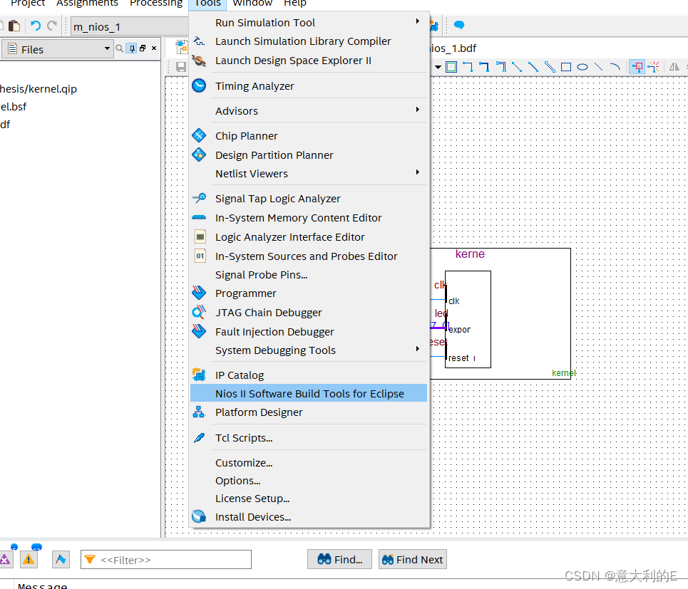
选择Nios II Software Build Tools for Eclipse
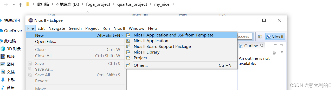
在eclipse里面选择第一栏
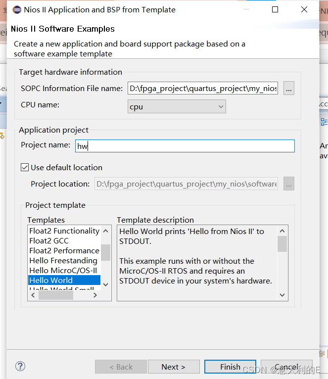
SOPC Information File name” 窗口中选择 kernel.sopcinfo 文件
修改主程序 hello_world.c
#include "system.h"
#include "altera_avalon_pio_regs.h"
#include "alt_types.h"
const alt_u8
led_data[8]={0x01,0x03,0x07,0x0F,0x1F,0x3F,0x7F,0xFF};
int main (void) {
	int count=0;
	alt_u8 led;
	volatile int i;
	while (1)
	{
		if (count==7)
		{count=0;}
		else
		{count++;}
		led=led_data[count];
		IOWR_ALTERA_AVALON_PIO_DATA(PIO_LED_BASE, led);
		i = 0;
		while (i<500000)
			i++;
		printf("Hello world!\n");
	}
	return 0;
}
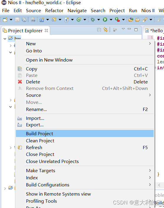
编译项目:
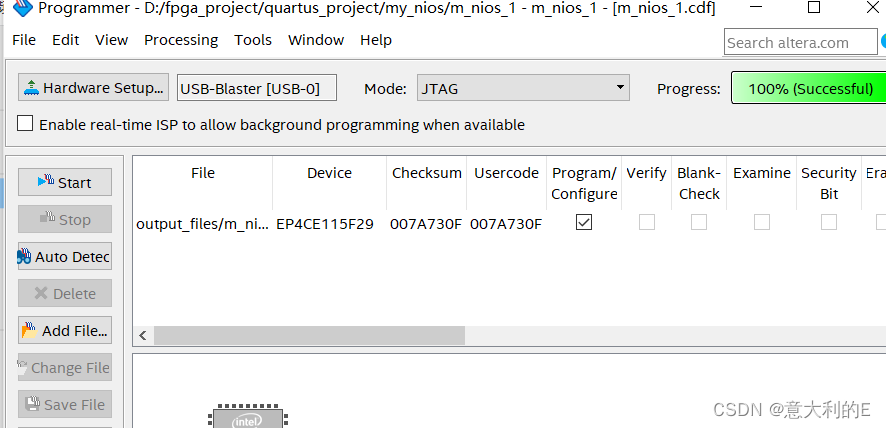
然后烧录文件到开发板:
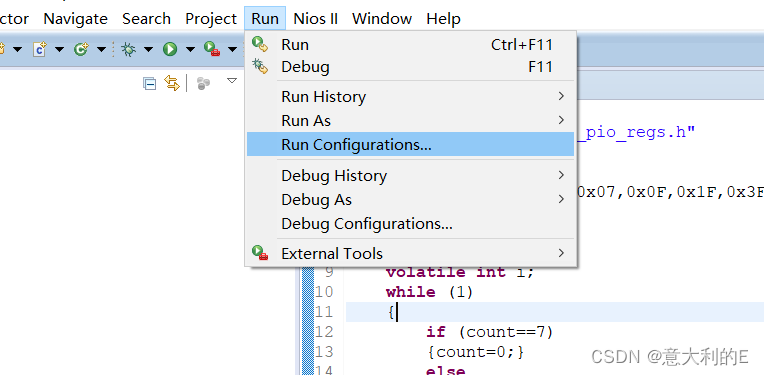
在eclipse中设置运行配置:
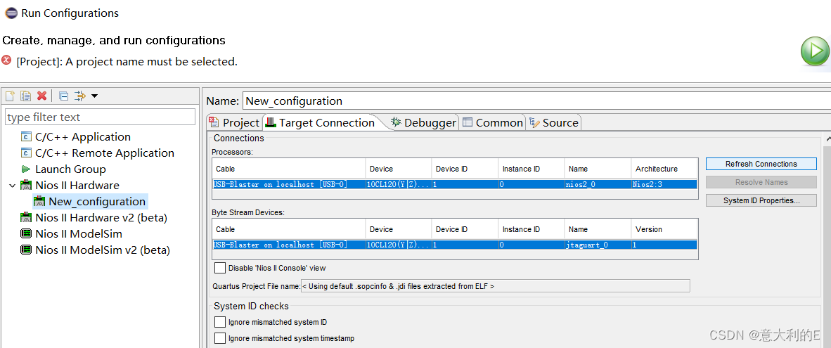
选择Refresh Connection,运行
old_led
serial
2.verilog方式实现流水灯
verilog代码:
module water_led
#(
  parameter CNT_MAX = 25'd24_999_999
)
(
input wire       sys_clk,
input wire       sys_rst_n,

output reg [3:0] led_out
);
reg [24:0] cnt;
reg cnt_flag;

always@(posedge sys_clk or negedge sys_rst_n)
    if(sys_rst_n == 1'b0)
	    cnt <= 25'd0;
	 else if (cnt == CNT_MAX)
	    cnt <= 25'd0;
	 else
	    cnt <= cnt + 25'd1;

always@(posedge sys_clk or negedge sys_rst_n)
    if(sys_rst_n == 1'b0)
	     cnt_flag <= 1'b0;
	 else if (cnt == (CNT_MAX - 25'd1 ))
	     cnt_flag <= 1'b1;
	 else
	     cnt_flag <= 1'b0;

always@(posedge sys_clk or negedge sys_rst_n)
    if(sys_rst_n == 1'b0)
	     led_out <= 4'b1110;
	 else if(cnt_flag == 1'b1)
	 led_out <= {led_out[2:0],led_out[3]};
	 else
	     led_out <=  led_out;

endmodule
testbench测试文件如下:
// Copyright (C) 2018  Intel Corporation. All rights reserved.
// Your use of Intel Corporation's design tools, logic functions
// and other software and tools, and its AMPP partner logic
// functions, and any output files from any of the foregoing
// (including device programming or simulation files), and any
// associated documentation or information are expressly subject
// to the terms and conditions of the Intel Program License
// Subscription Agreement, the Intel Quartus Prime License Agreement,
// the Intel FPGA IP License Agreement, or other applicable license
// agreement, including, without limitation, that your use is for
// the sole purpose of programming logic devices manufactured by
// Intel and sold by Intel or its authorized distributors.  Please
// refer to the applicable agreement for further details.

// *****************************************************************************
// This file contains a Verilog test bench template that is freely editable to
// suit user's needs .Comments are provided in each section to help the user
// fill out necessary details.
// *****************************************************************************
// Generated on "04/06/2023 16:22:04"

// Verilog Test Bench template for design : water_led
//
// Simulation tool : ModelSim (Verilog)
//

`timescale 1 ns/ 1 ps
module water_led_vlg_tst();
// constants
// general purpose registers
// test vector input registers
reg sys_clk;
reg sys_rst_n;
// wires
wire [3:0]  led_out;

// assign statements (if any)
water_led i1 (
// port map - connection between master ports and signals/registers
	.led_out(led_out),
	.sys_clk(sys_clk),
	.sys_rst_n(sys_rst_n)
);
initial
begin
 sys_clk=0;
    forever #10 sys_clk=~sys_clk;
end
initial
begin
 sys_rst_n=0;
    #20 sys_rst_n=1;
end
always
// optional sensitivity list
// @(event1 or event2 or .... eventn)
begin
// code executes for every event on sensitivity list
// insert code here --> begin

@eachvec;
// --> end
end
endmodule
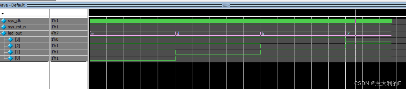
仿真波形:
注意在分配引脚时时钟信号应该选择接入系统时钟
运行效果:
new_led


 1175
1175


 被折叠的 条评论
为什么被折叠?
被折叠的 条评论
为什么被折叠?
 到【灌水乐园】发言


