


目录
说明:
- 将kitti数据集中 雷达点云图像投影到camera图像平面,
- 并生成 深度图的灰度图(灰度值=深度x256 保存成int16位图像(kitti中 depth benchmark的做法))
输入:
- P_rect_02: camera02相机内参
-
R_rect_00: 3x3 纠正旋转矩阵(使图像平面共面)(kitti特有的)
- Tr_velo_to_cam: 激光雷达到camera00的变换矩阵
输出:
- 投影图
- 深度图的灰度图
坐标系:
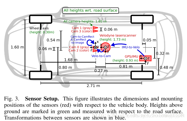
变换公式:
以下等式说明了如何使用齐次坐标在相机0的图像平面上将空间中的3D激光雷达点X投影到2D像素点Y(使用Kitti自述文件中的表示法):

RT_velo_to_cam * x:是将Velodyne坐标中的点x投影到编号为0的相机(参考相机)坐标系中R_rect00 *RT_velo_to_cam * x:是将Velodyne坐标中的点x投影到编号为0的相机(参考相机)坐标系中, 再以参考相机0为基础进行图像共面对齐修正(这是使用KITTI数据集的进行3D投影的必要操作)P_rect_00 * R_rect00 *RT_velo_to_cam * x:是将Velodyne坐标中的点x投影到编号为0的相机(参考相机)坐标系中, 再进行图像共面对齐修正, 然后投影到相机0的像素坐标系中. 如果将P_rect_00改成P_rect_2, 也就是从参考相机0投影到相机2的像素坐标系中(其他相机相对与相机0有偏移b(i)).- 原始论文: Vision meets Robotics: The KITTI Dataset
代码:
# -*- coding: utf-8 -*-

#  数据来源: calib_cam_to_cam.txt
#  下载链接: http://www.cvlibs.net/datasets/kitti/raw_data.php?type=road  >  2011_10_03_drive_0047  >  [calibration]
# R_rect_00: 9.999454e-01 7.259129e-03 -7.519551e-03 -7.292213e-03 9.999638e-01 -4.381729e-03 7.487471e-03 4.436324e-03 9.999621e-01
## P_rect_00: 7.188560e+02 0.000000e+00 6.071928e+02 0.000000e+00 0.000000e+00 7.188560e+02 1.852157e+02 0.000000e+00 0.000000e+00 0.000000e+00 1.000000e+00 0.000000e+00
# ...
## R_rect_02: 9.999191e-01 1.228161e-02 -3.316013e-03 -1.228209e-02 9.999246e-01 -1.245511e-04 3.314233e-03 1.652686e-04 9.999945e-01
# P_rect_02: 7.188560e+02 0.000000e+00 6.071928e+02 4.538225e+01 0.000000e+00 7.188560e+02 1.852157e+02 -1.130887e-01 0.000000e+00 0.000000e+00 1.000000e+00 3.779761e-03

#  数据来源: calib_velo_to_cam.txt
#  下载链接: http://www.cvlibs.net/datasets/kitti/raw_data.php?type=road  >  2011_10_03_drive_0047  >  [calibration]
#   calib_time: 15-Mar-2012 11:45:23
#   R: 7.967514e-03 -9.999679e-01 -8.462264e-04 -2.771053e-03 8.241710e-04 -9.999958e-01 9.999644e-01 7.969825e-03 -2.764397e-03
#   T: -1.377769e-02 -5.542117e-02 -2.918589e-01


# # png bin来源
# data_odometry_color/dataset/sequences/00/image_2
# data_odometry_velodyne/dataset/sequences/00/velodyne

import sys
import matplotlib.pyplot as plt
import matplotlib.image as mpimg
import numpy as np
import utils
from PIL import Image
import math


#-----------------------------------相机02内参矩阵-----------------------------------
P_rect_02 = np.array( [ 7.188560000000e+02, 0.000000000000e+00, 6.071928000000e+02, 4.538225000000e+01,
                        0.000000000000e+00,7.188560000000e+02, 1.852157000000e+02, -1.130887000000e-01,
                        0.000000000000e+00, 0.000000000000e+00, 1.000000000000e+00, 3.779761000000e-03]).reshape((3,4))

R_rect_00 = np.array( [ 9.999454e-01, 7.259129e-03, -7.519551e-03,
                        -7.292213e-03, 9.999638e-01, -4.381729e-03,
                        7.487471e-03, 4.436324e-03, 9.999621e-01]).reshape((3,3))

# R_rect_02 = np.array( [ 9.999191e-01, 1.228161e-02 -3,.316013e-03,
#                         -1.228209e-02, 9.999246e-01, -1.245511e-04,
#                         3.314233e-03, 1.652686e-04, 9.999945e-01]).reshape((3,3))


#velo激光雷达 到 相机00(此处已知条件重点注意) 的变换矩阵
Tr_velo_to_cam = np.array( [    7.967514e-03, -9.999679e-01, -8.462264e-04, -1.377769e-02,
                                -2.771053e-03, 8.241710e-04, -9.999958e-01, -5.542117e-02,
                                9.999644e-01, 7.969825e-03, -2.764397e-03, -2.918589e-01]).reshape((3,4))


#-----------------------------------数据文件位置---------------------------------------
velo_files = "./data/00_velodyne/000005.bin"
rgbimg = "./data/00_image_02/000005.png"
resultImg = "./data/result_merge.png"

data = {}
data['P_rect_20'] = P_rect_02
# Compute the velodyne to rectified camera coordinate transforms
data['T_cam0_velo'] = Tr_velo_to_cam
data['T_cam0_velo'] = np.vstack([data['T_cam0_velo'], [0, 0, 0, 1]])

# pattern1:
R_rect_00 = np.insert(R_rect_00,3,values=[0,0,0],axis=0)
R_rect_00 = np.insert(R_rect_00,3,values=[0,0,0,1],axis=1)
data['T_cam2_velo'] = R_rect_00.dot(data['T_cam0_velo']) #雷达 到 相机02的变换矩阵
print(data['T_cam2_velo'])

pointCloud = utils.load_velo_scan(velo_files)   #读取lidar原始数据
points = pointCloud[:, 0:3]                                           # 获取 lidar xyz (front, left, up)
points_homo = np.insert(points,3,1,axis=1).T    # 齐次化,并转置(一列表示一个点(x,y,z,1), 多少列就有多少个点)
points_homo = np.delete(points_homo,np.where(points_homo[0,:]<0),axis=1) #以列为基准, 删除深度x=0的点

proj_lidar = data['P_rect_20'].dot( data['T_cam2_velo'] ).dot(points_homo)  #相机坐标系3D点=相机02内参*激光雷达到相机02的变换矩阵*激光雷达3D点
cam = np.delete(proj_lidar,np.where(proj_lidar[2,:]<0),axis=1)  #以列为基准, 删除投影图像点中深度z<0(在投影图像后方)的点 #3xN
cam[:2,:] /= cam[2,:]   # 等价写法 cam[:2] /= cam[2] # 前两行元素分布除以第三行元素(归一化到相机坐标系z=1平面)(x=x/z, y =y/z)


# -----------------------------------将激光投影点绘制到图像平面:绘制原图------------------------------------
png = mpimg.imread(rgbimg)
IMG_H,IMG_W,_ = png.shape
plt.figure(figsize=((IMG_W)/72.0,(IMG_H)/72.0),dpi=72.0, tight_layout=True)
# restrict canvas in range
plt.axis([0,IMG_W,IMG_H,0])
# plt.axis('off')
plt.imshow(png) #在画布上画出原图

# filter point out of canvas
u,v,z = cam
u_out = np.logical_or(u<0, u>IMG_W)
v_out = np.logical_or(v<0, v>IMG_H)
outlier = np.logical_or(u_out, v_out)
cam = np.delete(cam,np.where(outlier),axis=1)
# generate color map from depth
u,v,z = cam

# 将激光投影点绘制到图像平面:绘制激光深度散点图
plt.scatter([u],[v],c=[z],cmap='rainbow_r',alpha=0.5,s=1)
plt.title("projection")
plt.savefig(resultImg,bbox_inches='tight')
plt.show()  #在画布上画出散点雷达深度投影


#-----------------------------------单独保存深度图像成灰度图像---------------------------------------------------
image_array = np.zeros((IMG_H, IMG_W), dtype=np.int16)
for i in range(cam.shape[1]):
    x = int(round(u[i]))
    y = int(round(v[i]))

    # x = math.ceil(u[i]) #向上取整
    # y = math.ceil(v[i])

    depth =  int(z[i]*256)
    if 0<x<image_array.shape[1] and 0<y<image_array.shape[0]:
        image_array[y,x] = depth

image_pil = Image.fromarray(image_array, 'I;16')
image_pil.save("result_16.png")


print("done")
结果:
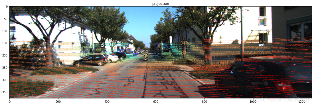

一帧激光点云+一张RGB图像得到彩色点云以及深度图
代码
#include <iostream>
#include <string>
#include <opencv2/opencv.hpp>
#include <pcl/io/pcd_io.h>
#include <pcl/point_types.h>
#include <pcl/common/transforms.h>
#include <pcl/visualization/pcl_visualizer.h>

typedef pcl::PointXYZRGBA PointT;
typedef pcl::PointCloud<PointT> PointCloud;
using namespace std;


PointCloud::Ptr TransformBinFile2Points(const std::string &binFile, const cv::Mat &imRGB,
                        const cv::Mat &Tcl, cv::Mat &imDepth);

PointCloud::Ptr TransformBinFile2PointsKITTI(const std::string &binFile, const cv::Mat &imRGB, cv::Mat &imDepth);
void Transform3DPointFromLidarToImage02KITTI(const cv::Mat &x3Dl, cv::Mat &x3Dc, cv::Point2i &point2D, float &d);

// backup funcitons
void Transform3DPointFromLidarToCamera(const cv::Mat &x3Dl, const cv::Mat &Tcl, cv::Mat &x3Dc);
void Transform3DPointInCameraTo2DImage(const cv::Mat &x3Dc, const cv::Mat &mK, cv::Point2i &point2D);

template<typename T>
void PrintCvMat(cv::Mat mat);


int main()
{

    // 1. read bin/pcd file and RGB file
    // 2. TransformBinFile2Points based on RGB image/ Tlc, TransformBinFile2ImDepth, GetPointsAndRGBCorrespondence
    // 2'. FOR LINGYUN: TransformPCDFile2Points
    std::string binFile = "/home/james/mytools/LidarPointReconstructionOneFrame/data/000005-lidar.bin";
    std::string rgbFile = "/home/james/mytools/LidarPointReconstructionOneFrame/data/000005-rgb.png";

    // test
    std::string pcdOutFile = "/home/james/mytools/LidarPointReconstructionOneFrame/data/000005-lidar.pcd";

    cv::Mat imRGB = cv::imread(rgbFile, cv::IMREAD_UNCHANGED);
    cv::Mat imDepth = cv::Mat::zeros(imRGB.rows, imRGB.cols, CV_32FC1);

    cv::Mat Tcl = (cv::Mat_<float>(4, 4)
            << 1, 0, 0, 0,
            0, 1, 0, 0,
            0, 0, 1, 0,
            0, 0, 0, 1);

    PointCloud::Ptr curentCloud;

    //curentCloud = TransformBinFile2Points(binFile, imRGB, Tcl, imDepth);
    curentCloud = TransformBinFile2PointsKITTI(binFile, imRGB,imDepth);

    // test: write to tiff file for imDepth
    cv::imwrite("/home/james/mytools/LidarPointReconstructionOneFrame/data/test_imDepth.tiff",
                imDepth);

    // test: write to pcd file for curentCloud.
    pcl::io::savePCDFile(pcdOutFile, *curentCloud);

    std::cout << "Hello, World!" << std::endl;
    return 0;
}

// generate depth image and 3D points with RGB color in Camera Coordinate System
// input: binFile of points from LIDAR, RGB image, Tcl(the transformation matrix from LIDAR to Camera)
// output: imDepth and 3D Points with RGB color in the Camera Coordinate System
PointCloud::Ptr TransformBinFile2PointsKITTI(const std::string &binFile, const cv::Mat &imRGB, cv::Mat &imDepth)
{
    PointCloud::Ptr tmpCloud(new PointCloud);

    // load point cloud
    fstream input(binFile.c_str(), ios::in | ios::binary);

    if (!input.good())
    {
        cerr << "Could not read file: " << binFile << endl;
        exit(EXIT_FAILURE);
    }
    input.seekg(0, ios::beg);

    //read bin file one point by one point
    int i;
    cv::Point2i point2D(0, 0);
    float d = 0.0;

    for (i = 0; input.good() && !input.eof(); i++)
    {
        pcl::PointXYZI p; // the 3D point in the LIDAR coordinate system without color information
        input.read((char *) &p.x, 3 * sizeof(float));// read the value of x,y,z
        input.read((char *) &p.intensity, sizeof(float)); // For KITTI datasets

        if (p.x < 1E-6 && p.y < 1E-6 && p.z < 1E-6)
            continue;

        // transform point3D in Lidar coordinate system to the camera
        cv::Mat x3Dl = (cv::Mat_<float>(3, 1) << p.x, p.y, p.z);

        // pniot 3D in camera02 in KITTI dataset
        cv::Mat x3Dc = cv::Mat::zeros(3, 1, CV_32F);


        Transform3DPointFromLidarToImage02KITTI(x3Dl, x3Dc, point2D, d);
        //PrintCvMat<float>(x3Dc);

        // d almost equal x3Dc.ptr<float>(2)[0]
        if (x3Dc.ptr<float>(2)[0] < 0 || d < 0)
            continue;

        const int &x = point2D.x;
        const int &y = point2D.y;
        //std::cout << "point2D: " << point2D.x << ", " << point2D.y << std::endl;

        if (x > 0 && x < imRGB.cols &&
            y > 0 && y < imRGB.rows)
        {
            // generate depth image in current camera coordinate system
            imDepth.ptr<float>(y)[x] = d; //TOTEST: or x3Dc.ptr<float>(2)[0];

            // put point3D in camera to tmpCloud with RGB color information
            PointT p3Dc;// the 3D point in the camera coordinate system with color information

            p3Dc.x = x3Dc.ptr<float>(0)[0];
            p3Dc.y = x3Dc.ptr<float>(1)[0];
            p3Dc.z = x3Dc.ptr<float>(2)[0];

            p3Dc.b = imRGB.ptr<uchar>(y)[x * 3];
            p3Dc.g = imRGB.ptr<uchar>(y)[x * 3 + 1];
            p3Dc.r = imRGB.ptr<uchar>(y)[x * 3 + 2];

            tmpCloud->push_back(p3Dc);
        }
    }

    input.close();

    return tmpCloud;
}


// input: x3Dl
// output: x3Dc and point2D
void Transform3DPointFromLidarToImage02KITTI(const cv::Mat &x3Dl, cv::Mat &x3Dc, cv::Point2i &point2D, float &d)
{
    // Vision meets Robotics: The KITTI Datase:
    // y = P_rect_02 * R_rect_00 * T_velo_to_cam00 * x
    cv::Mat P_rect_02 = (cv::Mat_<float>(3, 4)
            << 7.188560000000e+02, 0.000000000000e+00, 6.071928000000e+02, 4.538225000000e+01,
               0.000000000000e+00, 7.188560000000e+02, 1.852157000000e+02, -1.130887000000e-01,
               0.000000000000e+00, 0.000000000000e+00, 1.000000000000e+00, 3.779761000000e-03 );

//    cv::Mat P_rect_02_ = (cv::Mat_<float>(3, 4)
//            << 7.188560000000e+02, 0.000000000000e+00, 6.071928000000e+02, 0,
//            0.000000000000e+00, 7.188560000000e+02, 1.852157000000e+02, 0,
//            0.000000000000e+00, 0.000000000000e+00, 1.000000000000e+00, 0 );

    cv::Mat R_rect_00 = (cv::Mat_<float>(4, 4)
            << 9.999454e-01, 7.259129e-03, -7.519551e-03,   0,
               -7.292213e-03, 9.999638e-01, -4.381729e-03,  0,
               7.487471e-03, 4.436324e-03, 9.999621e-01,    0,
               0,               0,          0,              1);

    cv::Mat T_velo_to_cam00 = (cv::Mat_<float>(4, 4)
            << 7.967514e-03, -9.999679e-01, -8.462264e-04, -1.377769e-02,
              -2.771053e-03, 8.241710e-04, -9.999958e-01, -5.542117e-02,
               9.999644e-01, 7.969825e-03, -2.764397e-03, -2.918589e-01,
               0,               0,          0,              1);

    // T_cam00_to_cam02 = (R_02, t_02)
    cv::Mat T_cam00_to_cam02 = (cv::Mat_<float>(4, 4)
            <<  9.999788e-01, -5.008404e-03, -4.151018e-03,  5.954406e-02,
                4.990516e-03, 9.999783e-01, -4.308488e-03,  -7.675338e-04,
                4.172506e-03, 4.287682e-03, 9.999821e-01,   3.582565e-03,
                0,               0,          0,              1);


    cv::Mat x3Dl_h = (cv::Mat_<float>(4, 1)
            << x3Dl.ptr<float>(0)[0],
               x3Dl.ptr<float>(1)[0],
               x3Dl.ptr<float>(2)[0],
               1                      );

    cv::Mat x3Dc_cam00 = T_velo_to_cam00 * x3Dl_h;
    cv::Mat rectified_x3Dc = P_rect_02 * R_rect_00 * x3Dc_cam00;
    //PrintCvMat<float>(rectified_x3Dc);

    // output the point 2D and depth in image02
    d = rectified_x3Dc.ptr<float>(2)[0];
    point2D.x = rectified_x3Dc.ptr<float>(0)[0]/d;
    point2D.y = rectified_x3Dc.ptr<float>(1)[0]/d;
    //std::cout << "point2D_rectified_x3Dc: " <<  point2D.x << ", " <<  point2D.y << ", d = "<< d << std::endl;

    cv::Mat theory_x3Dc = T_cam00_to_cam02 * x3Dc_cam00;
    //PrintCvMat<float>(theory_x3Dc);

    // output the point 3D in camera02
    x3Dc = (cv::Mat_<float>(3, 1)
           <<   theory_x3Dc.ptr<float>(0)[0],
                theory_x3Dc.ptr<float>(1)[0],
                theory_x3Dc.ptr<float>(2)[0]);

    //TEST   // 跟 rectified_x3Dc.ptr<float>(2)[0]; 误差在3cm以内,后续可以对比效果做选择 d=? TODO
    //std::cout << "theory_x3Dc d = " <<  theory_x3Dc.ptr<float>(2)[0] << std::endl;
}


// generate depth image and 3D points with RGB color in Camera Coordinate System
// input: binFile of points from LIDAR, RGB image, Tcl(the transformation matrix from LIDAR to Camera)
// output: imDepth and 3D Points with RGB color in the Camera Coordinate System
PointCloud::Ptr TransformBinFile2Points(const std::string &binFile, const cv::Mat &imRGB, const cv::Mat &Tcl, cv::Mat &imDepth)
{
    //1. read bin file one point by one point => point3DInLidar
    //2. transform point3DInLidar to camera coordinate system  => point3DInCamera
    //3. transform point3DInCamera to Image coordinate system => point2DInImage
    //4. if point2DInImage in the plane of rgb image, put point2DInImage to imDepth
    //5. if point2DInImage in the plane of rgb image, put point3DInCamera to tmpCloud with RGB color information

    PointCloud::Ptr tmpCloud(new PointCloud);

    // load point cloud
    fstream input(binFile.c_str(), ios::in | ios::binary);

    if (!input.good())
    {
        cerr << "Could not read file: " << binFile << endl;
        exit(EXIT_FAILURE);
    }
    input.seekg(0, ios::beg);

    cv::Mat K = (cv::Mat_<float>(3, 3)
            << 1, 0, 0,
            0, 1, 0,
            0, 0, 1);

    //read bin file one point by one point
    int i;
    cv::Point2i point2D(0, 0);
    for (i = 0; input.good() && !input.eof(); i++)
    {
        pcl::PointXYZI p; // the 3D point in the LIDAR coordinate system without color information
        input.read((char *) &p.x, 3 * sizeof(float));// read the value of x,y,z
        input.read((char *) &p.intensity, sizeof(float)); // For KITTI datasets

        if (p.x < 1E-6 && p.y < 1E-6 && p.z < 1E-6)
            continue;

        // transform point3D in Lidar coordinate system to the camera
        cv::Mat x3Dl = (cv::Mat_<float>(3, 1) << p.x, p.y, p.z);
        cv::Mat x3Dc = cv::Mat::zeros(3, 1, CV_32F);

        PrintCvMat<float>(x3Dl);
        Transform3DPointFromLidarToCamera(x3Dl, Tcl, x3Dc);
        PrintCvMat<float>(x3Dc);

        if (x3Dc.ptr<float>(2)[0] < 0)
            continue;

        // transform point3D in camera to point2D in pixel coordinate system
        point2D.x = 0;
        point2D.y = 0;
        Transform3DPointInCameraTo2DImage(x3Dc, K, point2D);

        const int &x = point2D.x;
        const int &y = point2D.y;
        std::cout << "point2D: " << point2D.x << ", " << point2D.y << std::endl;
        if (x > 0 && x < imRGB.cols &&
            y > 0 && y < imRGB.rows)
        {
            // generate depth image in current camera coordinate system
            imDepth.ptr<float>(y)[x] = x3Dc.ptr<float>(2)[0];

            // put point3D in camera to tmpCloud with RGB color information
            PointT p3Dc;// the 3D point in the camera coordinate system with color information
            p3Dc.z = x3Dc.ptr<float>(2)[0];
            p3Dc.x = x3Dc.ptr<float>(0)[0];
            p3Dc.y = x3Dc.ptr<float>(1)[0];
            p3Dc.b = imRGB.ptr<uchar>(y)[x * 3];
            p3Dc.g = imRGB.ptr<uchar>(y)[x * 3 + 1];
            p3Dc.r = imRGB.ptr<uchar>(y)[x * 3 + 2];
            tmpCloud->push_back(p3Dc);
        }
    }

    // test
    cv::imwrite("/home/james/mytools/LidarPointReconstructionOneFrame/data/test_imDepth.tiff",
                imDepth);

    input.close();
    return tmpCloud;
}

// transform the 3D points form LIDAR coordinate system to camera coordinate system
// input:  x3Dl and Tcl
// output: x3Dc
void Transform3DPointFromLidarToCamera(const cv::Mat &x3Dl, const cv::Mat &Tcl, cv::Mat &x3Dc)
{
    cv::Mat Rcl = Tcl.rowRange(0, 3).colRange(0, 3);
    cv::Mat tcl = Tcl.rowRange(0, 3).col(3);
    x3Dc = Rcl * x3Dl + tcl;

}

// transform the 3D points in camera coordinate system to pixel coordinate system
// input: x3Dc and K
// output: point2D
void Transform3DPointInCameraTo2DImage(const cv::Mat &x3Dc, const cv::Mat &mK, cv::Point2i &point2D)
{
    const float &fx = mK.at<float>(0, 0);
    const float &fy = mK.at<float>(1, 1);
    const float &cx = mK.at<float>(0, 2);
    const float &cy = mK.at<float>(1, 2);

    point2D.x = (int) (fx * x3Dc.at<float>(0, 0) / x3Dc.at<float>(2, 0) + cx); // fx * X / Z + cx
    point2D.y = (int) (fy * x3Dc.at<float>(1, 0) / x3Dc.at<float>(2, 0) + cy); // fx * Y / Z + cy


}


template<typename T>
void PrintCvMat(cv::Mat mat)
{
    T value;
    cout << "\n-------------------------------" << endl;
    for (int j = 0; j < mat.rows; j++)
    {
        for (int i = 0; i < mat.cols; i++)
        {
            value = mat.ptr<T>(j)[i];
            cout << value << "\t\t";
        }
        cout << endl;
    }
    cout << "\n-------------------------------" << endl;
}
CMakeLists.txt
cmake_minimum_required(VERSION 3.17)
project(LidarPointReconstructionOneFrame)
SET(CMAKE_BUILD_TYPE "Debug")

set(CMAKE_CXX_STANDARD 11)

find_package(OpenCV 3)
if(NOT OpenCV_FOUND)
    find_package(OpenCV 2.4.3 QUIET)
    if(NOT OpenCV_FOUND)
        message(FATAL_ERROR "OpenCV > 2.4.3 not found.")
    endif()
endif()

find_package(Eigen3 3.1.0 REQUIRED)

find_package( PCL REQUIRED COMPONENT common io visualization filters)
set(PCL_INCLUDE_DIRS /usr/include/pcl-1.8)
link_directories(${PCL_LIBRARY_DIRS})

add_definitions( ${PCL_DEFINITIONS} )

include_directories(
        ${EIGEN3_INCLUDE_DIR}
        ${PCL_INCLUDE_DIRS}
)

add_executable(LidarPointReconstructionOneFrame main.cpp)

target_link_libraries(${PROJECT_NAME}
        ${OpenCV_LIBS}
        ${EIGEN3_LIBS}
        ${PCL_LIBRARIES}
        )
效果:
彩色点云图:

与RGB图像对应的深度图:
参考:
- https://github.com/azureology/kitti-velo2cam
- python3.6 > sit-packages>pykitti>odometry.py


 1287
1287


 被折叠的 条评论
为什么被折叠?
被折叠的 条评论
为什么被折叠?
 到【灌水乐园】发言


