


Clocking blocks在UVM的验证中使用非常重要,主要用于对输入的激励驱动和对输出的采样,但是很多人可能都不知道。
如下图所示,理想情况下,我们会在图中蓝线处进行驱动或者采样,从而尽可能避免竞争冒险。

SystemVerilog考虑到了这一点,可以参考寄存器时序逻辑运行的方式,即将所有的输出端都进行寄存来尽可能避免验证环境中的竞争冒险。因为毕竟建立时间和保持时间等时序方面的验证不该由DV来负责,也就是说说默认情况下,我们DV要假定该RTL将来综合后的电路在timing上没有问题,因此我们可以考虑利用Clocking blocks来构造一个理想的驱动和采样interface的环境。
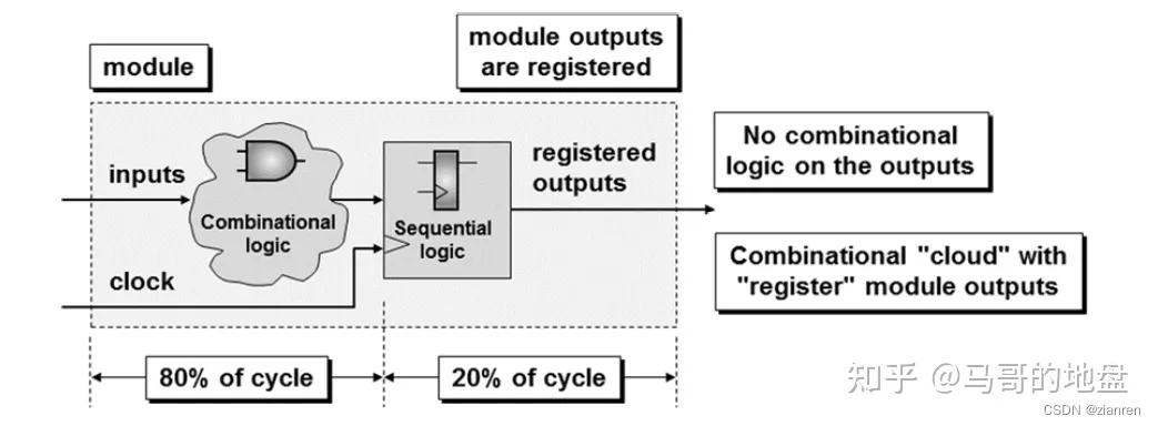
上图所示,举个例子,一般情况下一个cycle中大部分,比如80%的时间用于输入端的组合逻辑的路径延迟,剩余的20%的cycle时间用于寄存和输出。
那么以上面为例,如何来使用Clocking blocks呢?
直接来看代码:
clocking cb1 @(posedge clk)
    default input #1step output (`CYCLE * 0.2);
    input <list of all inputs> ;
    output <list of all outputs>;
endclocking
在我们的env环境中,寄存输出的值即是我们要驱动到DUT interface上的激励,而env环境中的输入,则需要在interface上采样并且被传递到testbench中。
最佳采样DUT interface端数据的时间,是刚好在下一个时钟跳变沿改变输出端数据之前进行采样,这个时候应该是最稳定的时候,只是这里的input我们使用了#1step的延迟,即相当于仿真时间精度。
最佳驱动时间,应该是在时钟跳变沿之前的10%~20%,因为那个时候激励也最稳定,要在DUT采样interface之前预留一些时间。
下面来看个例子,首先看这里的interface。
interface dut_if (input clk);
    logic [15:0] dout;
    logic [15:0] din;
    logic ld, inc, rst_n;

    clocking cb1 @(posedge clk);
        default input #1step output `Tdrive;
        input dout;
        output din;
        output ld, inc, rst_n;
    endclocking
endinterface
驱动interface
下面来看如何在driver里将transaction驱动到interface上。
task drive_tr (trans1 tr);
@vif.cb1;
vif.cb1.din <= tr.din;
vif.cb1.ld <= tr.ld;
vif.cb1.inc <= tr.inc;
vif.cb1.rst_n <= tr.rst_n;
endtask
很简单,我们通过Clocking blocks来完成输出端的驱动。
通常我们在driver里驱动之前会对interface做一下初始化,比如这里一般会使用initialize方法。
如果是前序模块给的输出的话,那么需要置成对应的有效值,否则初始化为x不定态来模拟最真实的场景,注意这需要EDA工具提供进一步的支持。
class tb_driver extends uvm_driver #(trans1);
    `uvm_component_utils(tb_driver)
    virtual dut_if vif;

    function new (string name, uvm_component parent);
        super.new(name, parent);
    endfunction

    task run_phase(uvm_phase phase);
        trans1 tr;
        initialize();
        forever begin
        seq_item_port.get_next_item(tr);
        drive_tr(tr);
        seq_item_port.item_done();
        end
    endtask

    task initialize(); // @0 - Does not use clocking block
        vif.rst_n <= '0;
        vif.ld <= '1;
        vif.inc <= '1;
        vif.din <= 'dx;
    endtask

    task drive_tr (trans1 tr);
        @vif.cb1;
        vif.cb1.din <= tr.din;
        vif.cb1.ld <= tr.ld;
        vif.cb1.inc <= tr.inc;
        vif.cb1.rst_n <= tr.rst_n;
    endtask
endclass
监测interface
下面再来看如何采样interface上的信号。
class tb_monitor extends uvm_monitor;
    `uvm_component_utils(tb_monitor)
    virtual dut_if vif;
    uvm_analysis_port #(trans1) aport;

    function new (string name, uvm_component parent);
    super.new(name, parent);
    endfunction

    function void build_phase(uvm_phase phase);
        super.build_phase(phase);
        aport = new("aport", this); // build the analysis port
    endfunction

    task run_phase(uvm_phase phase);
        trans1 tr;
        tr = trans1::type_id::create("tr");
        //---------------------------------------
        forever begin
            sample_dut(tr);
            aport.write(tr);
        end
    endtask
    //-----------------------------------------------
    // sample_dut assumed to be synced to posedge clk
    // except for first sample at time-0
    //-----------------------------------------------
    task sample_dut (output trans1 tr);
        trans1 t = trans1::type_id::create("t");
        //---------------------------------------------
        // Sample DUT synchronous inputs on posedge clk.
        // DUT inputs should have been valid for most
        // of the previous clock cycle
        //---------------------------------------------
        t.din = vif.din;
        t.ld = vif.ld;
        t.inc = vif.inc;
        t.rst_n = vif.rst_n;
        //---------------------------------------------
        // Wait for posdege clk and sample outputs #1step before.
        // Also re-sample and check async control input signals
        //---------------------------------------------
        @vif.cb1;
        if (!vif.rst_n) t.rst_n = '0; // async reset
        t.dout = vif.cb1.dout;
        //---------------------------------------------
        tr = t;
    endtask
endclass
如果monitor的信号在clocking block是output方向的话(对应的即RTL的input方向),则使用t.xxx = vif.xxx的语句先monitor到interface上的信号值,然后等时钟沿@vif.cb1来进行同步,那么可以理解为在时钟上升沿到来之前,output方向的信号已经稳定(意味着RTL的输入端激励在时钟上升沿到来之前已经稳定),所以在时钟沿之前进行阻塞完成赋值。
然后对于input方向的信号dout(对应RTL的output方向),则使用cb1的三段式来赋值,即t.dout = vif.cb1.dout,主要是考虑RTL的output应该在时钟上升沿之后才会将有效的结果输出值驱动到interface上,因此这里需要等待1step的延迟之后通过阻塞赋值来monitor到RTL输出端驱动到interface上的稳定的值。
因此需要区分不同interface的类型,采用不同的写法。
但问题来了,如下图所示,如果这个rst_n是个异步复位且刚好在一个cycle之间进行了异步复位,那么如何monitor到该动作呢?

那么首先我们需要对interface做如下修改:
interface dut_if (input clk);
    logic [15:0] dout;
    logic [15:0] din;
    logic ld, inc, rst_n;
    logic reset_n;
    //----------------------------------------------------
    // Sticky reset_n signal to capture short rst_n pulses
    //----------------------------------------------------
    always_ff @(posedge clk, negedge rst_n)
        if (!rst_n) reset_n <= '0;
        else reset_n <= '1;
    clocking cb1 @(posedge clk);
        default input #1step output `Tdrive;
        input dout;
        output din;
        output ld, inc, rst_n;
        input reset_n;
    endclocking
endinterface
然后再来修改monitor。
class tb_monitor extends uvm_monitor;
    `uvm_component_utils(tb_monitor)
    ...
    task run_phase(uvm_phase phase);
        trans1 tr;
        tr = trans1::type_id::create("tr");
        //---------------------------------------
        forever begin
            sample_dut(tr);
            aport.write(tr);
        end
    endtask

    task sample_dut (output trans1 tr);
        trans1 t = trans1::type_id::create("t");
        t.din = vif.din;
        t.ld = vif.ld;
        t.inc = vif.inc;
        t.rst_n = vif.rst_n;
        //---------------------------------------------
        // ...
        // Sample the sticky-bit reset_n to update rst_n if needed
        //---------------------------------------------
        @vif.cb1;
        if (!vif.cb1.reset_n) t.rst_n = '0; // async reset
        t.dout = vif.cb1.dout;
        //---------------------------------------------
        tr = t;
    endtask
endclass
https://zhuanlan.zhihu.com/p/382248330


 2149
2149


 被折叠的 条评论
为什么被折叠?
被折叠的 条评论
为什么被折叠?
 到【灌水乐园】发言


