


提示:文章写完后,目录可以自动生成,如何生成可参考右边的帮助文档
前言
使用VHDL语言搭建一个简易状态机模版,包含次态、现态和输出,以循环点亮LED为例编写;同时讲述一些常见语法知识。
提示:任何文章不要过度深思!万事万物都经不起审视,因为世上没有同样的成长环境,也没有同样的认知水平,更「没有适用于所有人的解决方案」 ;不要急着评判文章列出的观点,只需代入其中,适度审视一番自己即可,能「跳脱出来从外人的角度看看现在的自己处在什么样的阶段」才不为俗人 。怎么想、怎么做,全在乎自己「不断实践中寻找适合自己的大道」
一、VHDL通用模版
//VHDL所需使用的库文件
LIBRARY ieee;
USE ieee.std_logic_1164.all;


//实体,包含输入输出端口
ENTITY w IS
  PORT (
  ------------------------------------------------------------------------------
  --Insert input ports below
    clock      : IN  std_logic;                    -- input bit example
    val        : IN  std_logic_vector(3 DOWNTO 0); -- input vector example
  ------------------------------------------------------------------------------
  --Insert output ports below
    max        : OUT std_logic;                    -- output bit example
    cpt        : OUT std_logic_vector(3 DOWNTO 0)  -- output vector example
    );
END w;

--------------------------------------------------------------------------------
--Complete your VHDL description below
--------------------------------------------------------------------------------
//结构体  用于编写文本
ARCHITECTURE TypeArchitecture OF w IS

BEGIN


END TypeArchitecture;
二、常见数据类型
1.数据类型
std_logic:表示数字电路中的逻辑信号,其取值为‘0’或‘1’,也可以是高阻态‘Z’,无效态‘X’,不确定态‘U’等。

integer:表示整数类型,可以取正整数、负整数或零。

boolean:表示布尔类型,其取值为TRUE或FALSE。

std_ulogic:与std_logic相似,但是不支持无效态和不确定态。

std_logic_vector:表示一组std_logic信号,可以是任意长度的向量。

unsigned:表示无符号整数类型,可以取0到2^n-1的值,n为unsigned的位数。

signed:表示有符号整数类型,可以取-2^(n-1)到2^(n-1)-1的值,n为signed的位数。

real:表示实数类型,可以包括小数和整数部分。
2.基本语法
2.1 signal使用
信号的基本语法如下:

signal signal_name : signal_type [:= default_value];

其中,signal_name 是信号的名称,signal_type 是信号的类型,default_value 是可选的默认值。
示例JK触发器:
entity JK is
  Port (
    clk,rst,J,K:in std_logic;
    Q : out std_logic

  );
end JK;

architecture JK of JK is
signal Q_reg : std_logic;
begin
     process(clk ,rst)
     begin
        if(rst = '1' ) then
            Q_reg <= '0';
        elsif(clk' event and clk = '1' ) then
            if(J='0'and K='1') then
                Q_reg <= '0';
            elsif (J='1'and K='0') then
                Q_reg <= '1';
            elsif (J='0'and K='0') then
                Q_reg <= Q_reg;
            elsif (J='1'and K='1') then
                Q_reg <= not Q_reg;
            end if;
        end if;

    end process;
    Q <= Q_reg;
end JK;
注意:使用signal定义变量时其变量可以超出process使用,可作用于全局,其如果放在process中进行赋值,则Q值响应会延迟半拍。
architecture JK of JK is
signal Q_reg : std_logic;
begin
     process(clk ,rst)
     begin
        if(rst = '1' ) then
            Q_reg <= '0';
        elsif(clk' event and clk = '1' ) then
            if(J='0'and K='1') then
                Q_reg <= '0';
            elsif (J='1'and K='0') then
                Q_reg <= '1';
            elsif (J='0'and K='0') then
                Q_reg <= Q_reg;
            elsif (J='1'and K='1') then
                Q_reg <= not Q_reg;
            end if;
        end if;
     Q <= Q_reg;
    end process;

end JK;
2.2 Variable使用
基本语法
variable variable_name : variable_type [:= default_value];
示例1:
variable count :STD_LOGIC_VECTOR(7 downto 0) := "00000000";
示例2:
variable sum :integer range 0 to 16  := 0;
示例:
----------------------------------------------------------------------------------

library IEEE;
use IEEE.STD_LOGIC_1164.ALL;

-- Uncomment the following library declaration if using
-- arithmetic functions with Signed or Unsigned values
--use IEEE.NUMERIC_STD.ALL;

-- Uncomment the following library declaration if instantiating
-- any Xilinx leaf cells in this code.
--library UNISIM;
--use UNISIM.VComponents.all;

entity MUX_16_1 is
  Port (
       EN :in STD_LOGIC;
       input_data : in STD_LOGIC_VECTOR(15 downto 0);
       led : out STD_LOGIC

  );
end MUX_16_1;

architecture MUX_16_1 of MUX_16_1 is

begin
    process(EN,input_data)
    variable sum :integer range 0 to 16  := 0;
    begin
         sum := 0;
         if(EN = '0') then
            led <= '0';
         else
            for i in 0 to 15 loop
                if(input_data(i) = '1')  then
                    sum := sum + 1;
                    if(sum >= 7) then
                        led <= '1';
                    else
                        led <= '0';
                    end if;

                else
                    sum := sum;

                end if;
            end loop;

        end if;
    end process;


end  MUX_16_1;
注意:variable只能作用于process内部,为局部变量。
三、通用状态机模版
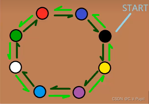
3.1 问题描述
实现led转换,状态图如下:
3.2代码编写
library IEEE;
use IEEE.STD_LOGIC_1164.ALL;

-- Uncomment the following library declaration if using
-- arithmetic functions with Signed or Unsigned values
--use IEEE.NUMERIC_STD.ALL;

-- Uncomment the following library declaration if instantiating
-- any Xilinx leaf cells in this code.
--library UNISIM;
--use UNISIM.VComponents.all;

entity rgb_state is
  Port (
        clk,rst,oe:in STD_LOGIC;
        led:out STD_LOGIC_VECTOR(2 downto 0)


  );
end rgb_state;

architecture rgb of rgb_state is
type state_type is  (red,blue,green,yellow,purple,cyan,white,black);
signal current_state,next_state:state_type;
begin
    cs:process(clk,rst)
    begin
        if(rst = '1') then
            current_state <= black;
        elsif(clk' event and clk = '1') then
            current_state <= next_state;
        end if;
    end process;
    ns:process(current_state,oe)
    begin
        case current_state is
            when black =>  if  oe = '1' then
                              next_state <= yellow;
                           else
                              next_state <= blue;
                           end if;
            when yellow => if oe = '1' then
                              next_state <= purple;
                           else
                              next_state <= black;
                           end if;
            when blue =>   if oe = '1' then
                              next_state <= black;
                           else
                              next_state <= red;
                           end if;
            when purple =>   if oe = '1' then
                              next_state <= cyan;
                           else
                              next_state <= yellow;
                           end if;
            when red =>    if oe = '1' then
                              next_state <= blue;
                           else
                              next_state <= green;
                           end if;
            when cyan =>   if oe = '1' then
                              next_state <= white;
                           else
                              next_state <= purple;
                           end if;
            when green =>  if oe = '1' then
                              next_state <= red;
                           else
                              next_state <= white;
                           end if;
            when white =>  if oe = '1' then
                              next_state <= green;
                           else
                              next_state <= cyan;
                           end if;
        end case;
    end process;
    ol:process(current_state)
    begin
        case current_state is
            when black => led <= "000";
            when yellow=> led <= "110";
            when purple=> led <= "101";
            when cyan  => led <= "011";
            when white => led <= "111";
            when green => led <= "010";
            when red   => led <= "100";
            when blue  => led <= "001";
        end case;
    end process;

end rgb;
以上状态机包含次态、现态、输出,便于发现和修改。
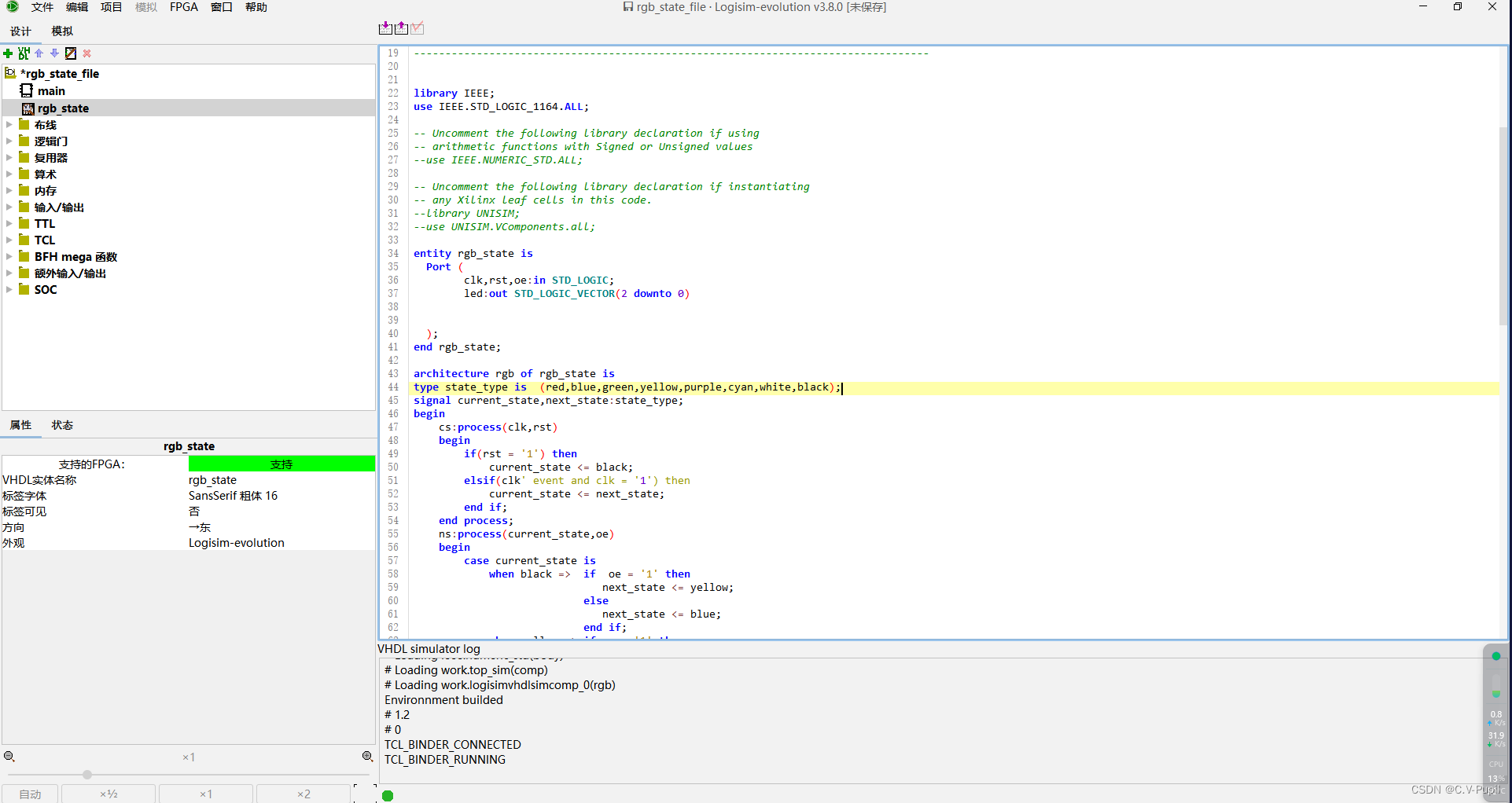
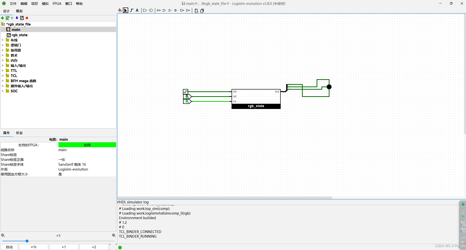
3.3 仿真
使用logisim-evolution软件仿真,图像化操作,无需写仿真文件。
源文件:
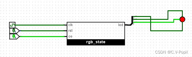
图像化仿真:


 1897
1897

 被折叠的 条评论
为什么被折叠?
被折叠的 条评论
为什么被折叠?
 到【灌水乐园】发言


