


 该博客介绍了如何使用LabVIEW FPGA进行串口通信的实现,包括蔡氏定律的理解、CP2102驱动电路、LabVIEW FPGA IP集成节点的网表文件编写,以及串口通信IP核的创建。通过Verilog代码展示了串口接收、发送和环回模块的详细设计,并提供了LabVIEW图形化编程的串口通信实例。
一、前情提要
上一节内容介绍了ngc、edf文件导入LabVIEW,Labview IP集成节点导入与编写方法,基本的按键控制流水灯,以及LabVIEW图形化的优点,本节内容承前节,对验证嵌入式中最基础的通信功能——串口通信。
【LabVIEW FPGA图形化】 ngc、edf网表文件的编写:LED流水灯
【LabVIEW FPGA图形化】 IP集成节点:按键控制LED
二、FPGA蔡氏定律
FPGA有两条蔡氏定律:
1、FPGA不仅仅是FPGA。
2、FPGA的最终目的是做出可用的电路。
FPGA的学习脱离不了硬件电路,但协议篇却并不要求外部的硬件电路,或者说外部的硬件电路如CP2102那些只是为了USB转TTL,方便电脑通信,对FOGA的逻辑没有实质影响。同理,外部用CH340、SP3232、或者转换成485、CAN通信都是可以做到的。
黑金ALINX在硬件上也提供了USB转TTL的驱动芯片:
CP2102驱动电路
开发板包含了Silicon Labs CP2102GM的USB-UAR芯片, USB接口采用MINI USB接口,可以用一根USB线将它连接到上PC的USB口进行串口数据通信 。
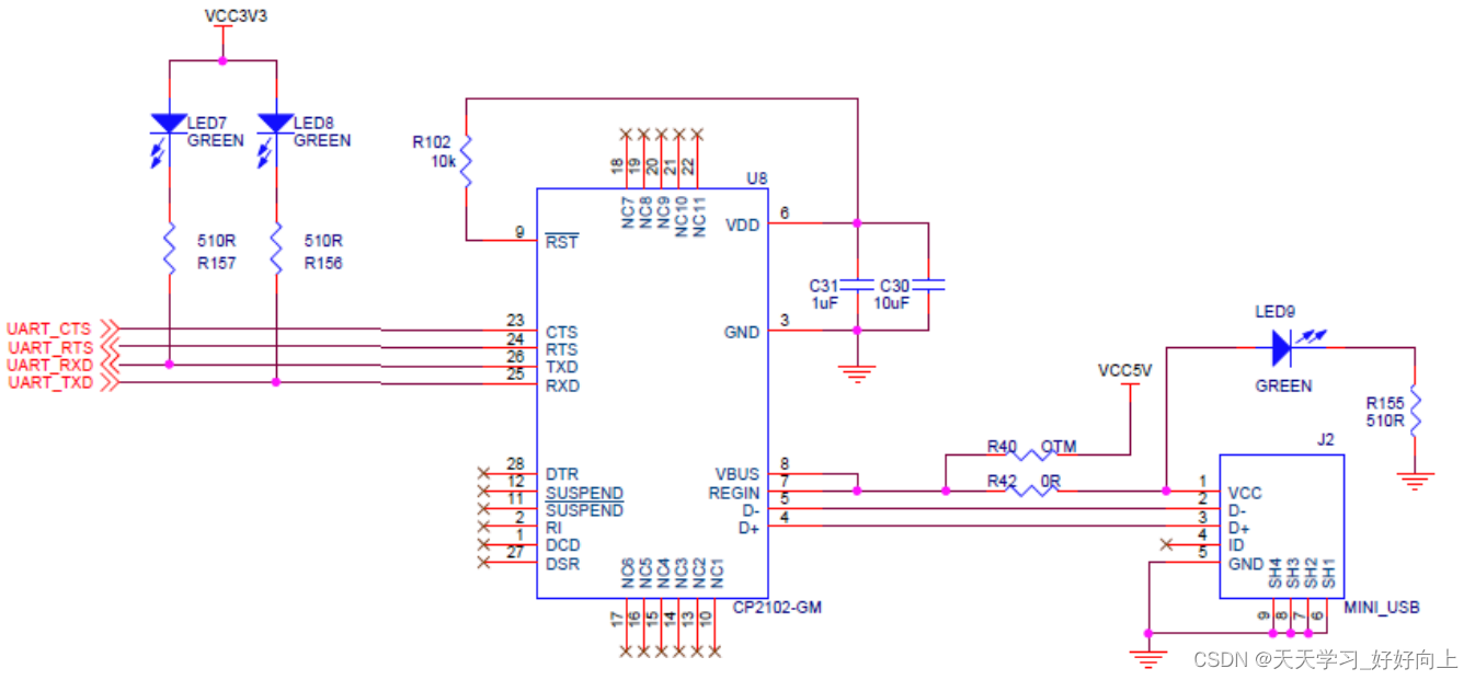
有了这个芯片,开发板就能通过MicroUSB与电脑进行通信:
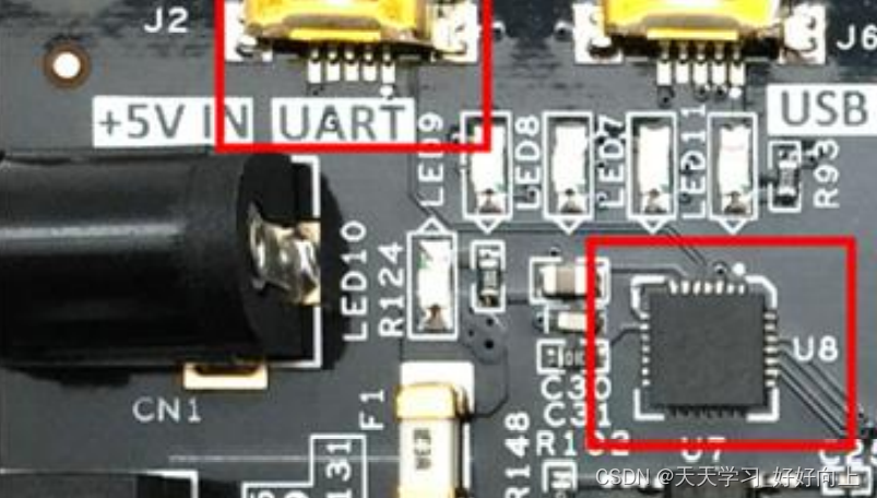
当然了CP2102比较容易烧,要是自己做项目的话,建议用CH340更可靠一点。
串口通信上面也有指示灯,指示当前的通信状态,比较直观。
三、LabVIEW FPGA IP集成节点网表文件的编写
编写网表,首先我们脑子里要有电路,也就是常常说的RTL视图,知道哪个端口输入和哪个端口输出是比较关键的,对于串口通信,不用想,一个串口输入模块、一个串口输出模块,如果要实现环回功能的话,还应该有一个环回模块。RTL视图:
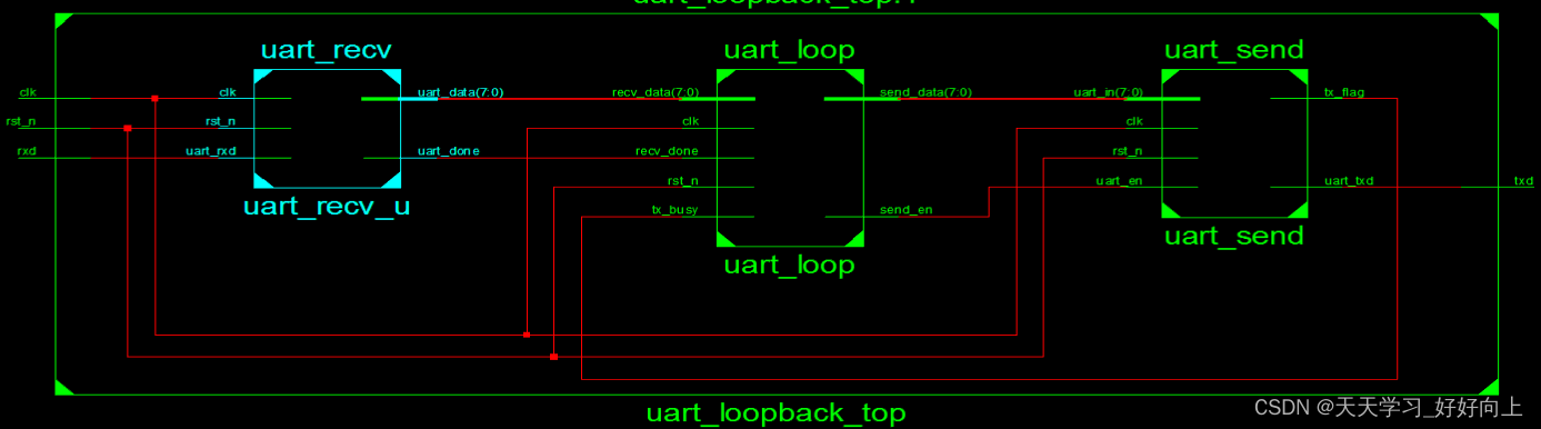
原谅我偷懒直接生成截图的,没有在Visio里边画出来,写程序的时候,我是直接画在纸上的,这个图也勉强能看、大意是接收模块接收串口发送的数据后,给环回模块,环回模块拿到数据后进行存储,当发送模块空闲时将数据给发送模块,构成一个环回。当然了,去掉串口环回模块之后,可以直接当作普通的串口环回模块使用。这个我们下一节会讲。
RTL视图反映出硬件之间的连接关系,有了这个,我们可以很清楚的定义输入和输出变量,根据每个变量之间的关系写出对应模块:
以下是串口接收模块
module uart_recv(
    input clk,
    input rst_n,
    input uart_rxd,
    output reg [7:0] uart_data,
    output reg uart_done

//	output reg rx_flag,
//	output reg uart_rxd_d0,
//	output reg uart_rxd_d1,
//	output reg [7:0] index

);

parameter CLK_FREQ= 50000000;
parameter UART_BAUD= 115200;
localparam UART_BAUD_CNT=CLK_FREQ/UART_BAUD;
reg [15:0] cnt;
reg baud_pulse;
reg [7:0] index;
reg uart_rxd_d0;
reg uart_rxd_d1;
reg	rx_flag;


always @(posedge clk or negedge rst_n) begin	//捕捉时钟下降沿  可以寄存两拍的值
    if(!rst_n) begin
    uart_rxd_d0<=1'b0;
    uart_rxd_d1<=1'b0;
    end
    else begin
    uart_rxd_d0<=uart_rxd;
    uart_rxd_d1<=uart_rxd_d0;
    end
end

always @(posedge clk or negedge rst_n) begin	//起始信号使能接收标志
    if(!rst_n)
	rx_flag<=1'b0;
	else if(index==9&&cnt==UART_BAUD_CNT/2)
	rx_flag<=1'b0;
	else if(uart_rxd_d0==0&&uart_rxd_d1==1'b1)//judge negedge
	rx_flag<=1'b1;
	else
	rx_flag<=rx_flag;
end


always @(posedge clk or negedge rst_n) begin	//rx_flag有效 计数值加一
    if(!rst_n)
       cnt<=1'b0;
     else if(rx_flag&&cnt!=UART_BAUD_CNT)
	 cnt<=cnt+1'b1;
	 else
	 cnt<=1'b0;
end


always @(posedge clk or negedge rst_n) begin	//波特率时间到 开始处理数据 辅助标志
    if(!rst_n)
	baud_pulse<=1'b0;
    else if(cnt==UART_BAUD_CNT)begin
    baud_pulse<=1'b1;
    end
    else begin
    baud_pulse<=1'b0;
    end
end

always @(posedge clk or negedge rst_n) begin	//波特率计数 0起始位  9停止位
    if(!rst_n)
    index<=1'b0;
	else if(rx_flag==0)	//清零在标志位拉低完成
    index<=1'b0;
    else if(rx_flag==1&&baud_pulse==1'b1)
		index<=index+1'b1;
    else
		index<=index;
end

always @(posedge clk or negedge rst_n) begin	//停止位拉高输出 下一级可读取
    if(!rst_n)
    uart_done<=1'b0;
    else if(index==8'd9&&cnt==2)
    uart_done<=1'b1;
    else
    uart_done<=1'b0;
   end


always @(posedge clk or negedge rst_n) begin	//将1-8 index 放入 0-7 uart——data数据暂存 done拉高后可一并读出
    if(!rst_n)
    uart_data<=8'b0;
    else if(cnt==UART_BAUD_CNT/2 && index>0 && index<9)begin  //从稳定状态读取比较稳妥  亚稳态用寄存两拍的值
    uart_data[index-1]<=uart_rxd_d1;//要保证原始异步脉冲信号至少要保证两个周期
    end
    else begin
    uart_data[index]<=uart_data[index];
    end
end


endmodule
有的初学者理解不了,串口通信的本质在接收端其实是将串行的数据转换成并行的一个过程,8位数据准备好了,用握手协议给下一级,需要特别注意的地方就是需要根据波特率调整分频而已。
发送模块的代码如下:
module uart_send(
	input 		clk,
	input 		rst_n,
	input [7:0]	uart_in,
	input 		uart_en,
	output reg tx_flag,
	output 	reg 	uart_txd
);


reg [7:0] uart_temp;

parameter CLK_FREQ=50000000;
parameter UART_BPS=115200;
localparam uart_cnt=CLK_FREQ/UART_BPS;
reg [31:0] cnt;
reg	[7:0]	index;


always @(posedge clk or negedge rst_n) begin	//发送开始工作标志
	if(!rst_n)
	tx_flag<=1'b0;
	else if(uart_en)
	tx_flag<=1'b1;
	else if(index==8'd10)
	tx_flag<=1'b0;
	else
	tx_flag<=tx_flag;
end


always @(posedge clk or negedge rst_n) begin	//先将数据读进来
	if(!rst_n)
	uart_temp<=8'd0;
	else if(uart_en==1'b1)
	uart_temp<=uart_in;
	else if(tx_flag==1'b0)
	uart_temp<=8'd0;
	else
	uart_temp<=uart_temp;
end

always @(posedge clk or negedge rst_n) begin	//产生串口时钟
	if(!rst_n)
	cnt<=1'b0;
	else if(tx_flag) begin
        if(cnt==uart_cnt)
        cnt<=1'b0;
        else
        cnt<=cnt+1'b1;
	end
	else
	cnt<=1'b0;
end

always @(posedge clk or negedge rst_n) begin	//输出索引+1
	if(!rst_n)
	index<=8'd0;
	else if(tx_flag==0)
	index<=1'b0;
	else if(cnt==uart_cnt-1)
	index<=index+1'b1;
	else
	index<=index;
end

always @(posedge clk or negedge rst_n) begin	//输出数据
	if(!rst_n)
	uart_txd<=1'b1;
	else if(tx_flag) begin
		case(index)
			4'd0 :	uart_txd<=1'b0			;
			4'd1 :	uart_txd<=uart_temp[0]	;
			4'd2 :	uart_txd<=uart_temp[1]	;
			4'd3 :	uart_txd<=uart_temp[2]	;
			4'd4 :	uart_txd<=uart_temp[3]	;
			4'd5 :	uart_txd<=uart_temp[4]	;
			4'd6 :	uart_txd<=uart_temp[5]	;
			4'd7 :	uart_txd<=uart_temp[6]	;
			4'd8 :	uart_txd<=uart_temp[7]	;
	        4'd9 :	uart_txd<=1'b1			;
			default: ;
		endcase
	end
	else
	uart_txd<=1'b1;
end


endmodule
发送模块的工作原理和接收模块刚好相反,将需要发送的并行数据转换成串行一位一位的发送,这样就不难理解,他们的速率不一样需要匹配的问题了。
环回模块像是关联接收和发送,进行握手的,代码如下:
module uart_loop(
	input 			clk,
	input 			rst_n,
	input 			recv_done,
	input 			[7:0]recv_data,
	input 			tx_busy,
	output 	reg 	[7:0]send_data,
	output 	reg		send_en

);

reg [7:0]temp_data;
reg rdy_send;

reg recv_done_d0;
reg recv_done_d1;

assign recv_done_flag=recv_done_d0&(~recv_done_d1);

always @(posedge clk or negedge rst_n) begin	//捕捉时钟下降沿  可以寄存两拍的值
    if(!rst_n) begin
    recv_done_d0<=1'b0;
    recv_done_d1<=1'b0;
    end
    else begin
    recv_done_d0<=recv_done;
    recv_done_d1<=recv_done_d0;
    end
end


always @(posedge clk or negedge rst_n) begin	//存储位判断
	if(!rst_n)
	rdy_send<=1'b0;
	else if(recv_done_flag==1'b1)
	rdy_send<=1'b1;
	else if(send_en==1'b1)
	rdy_send<=1'b0;
	else
	rdy_send<=rdy_send;
end

always @(posedge clk or negedge rst_n) begin	//将数据存储
	if(!rst_n)
	temp_data<=8'd0;
	else if(recv_done_flag==1'b1)
	temp_data<=recv_data;
	else
	temp_data<=temp_data;
end

always @(posedge clk or negedge rst_n) begin  //输出使能
	if(!rst_n)
	send_en<=1'b0;
	else if(rdy_send==1&&tx_busy==0)
	send_en<=1'b1;
	else
	send_en<=1'b0;
end

always @(posedge clk or negedge rst_n) begin  //使能有效 输出数据
	if(!rst_n)
	send_data<=8'd0;
	else if(send_en==1'b1)
	send_data<=temp_data;
	else
	send_data<=8'd0;
end

endmodule
这几个模块完成后,知道他们的连接关系,顶层文件其实也很好编写,只需要把各个模块串起来就可以了。
//`timescale 1ns / 1ps
//
// Company:
// Engineer:
//
// Create Date: 2022/11/02 10:48:07
// Design Name:
// Module Name: uart_loopback_top
// Project Name:
// Target Devices:
// Tool Versions:
// Description:
//
// Dependencies:
//
// Revision:
// Revision 0.01 - File Created
// Additional Comments:
//
//


module uart_loopback_top(
    input   clk,
    input   rst_n,
    input   rxd,
    output   txd
    );

 wire [7:0] uart_in;
 wire send_en;
 wire tx_busy;
 wire uart_done;
 wire [7:0] recv_data;

 uart_recv uart_recv_u(
    .clk        (clk),
    .rst_n      (rst_n),
    .uart_rxd   (rxd),
    .uart_data  (recv_data),
    .uart_done  (uart_done)

 );
 uart_loop uart_loop(
    .clk        (clk),
    .rst_n      (rst_n),
    .recv_done  (uart_done),
    .recv_data  (recv_data),
    .tx_busy    (tx_busy),
    .send_data  (uart_in),
    .send_en    (send_en)

 );
 uart_send uart_send(
    .clk        (clk),
    .rst_n      (rst_n),
    .uart_in  (uart_in),
    .uart_en  (send_en),
    .tx_flag    (tx_busy),
    .uart_txd  (txd)

 );

endmodule
编写好顶层文件后需要修改综合参数,在Xilinx Specific Options中去掉 Add I/O Buffer选项,不添加I/O buffer并综合。
四、FPGA图形化程序编写
将上面程序生成的uart_loopback_top.ngc 添加到vi所在的工程目录下,调用IP节点,对其各个端口进行连线。
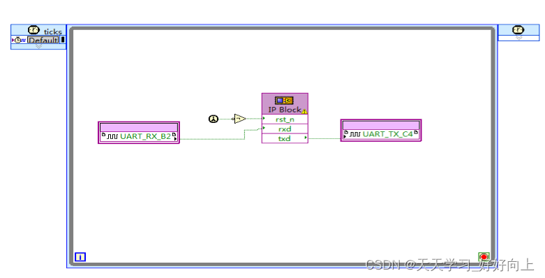
NI官方提供的串口通信例程比较复杂,是用纯图形化语言编写的,占用资源比较多,反而观之底层代码实现起来有它的优势。看着程序也比较简单,我们编译下载试试。
添加网表文件后,由于复位为低电平复位,因此需要在程序首次调用后或非门取反,下载至开发板后我们用串口助手发送数据。
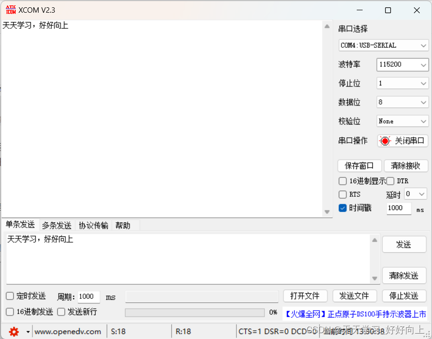
发送什么数据就可以接收到什么数据,串口环回实验的VI、ngc,代码文件都在串口环回通信资源文件。
五、串口通信IP核
有了前面串口环回实验的基础,去掉中间的环回模块,将数据直接输出,就构成了串口通信IP核。
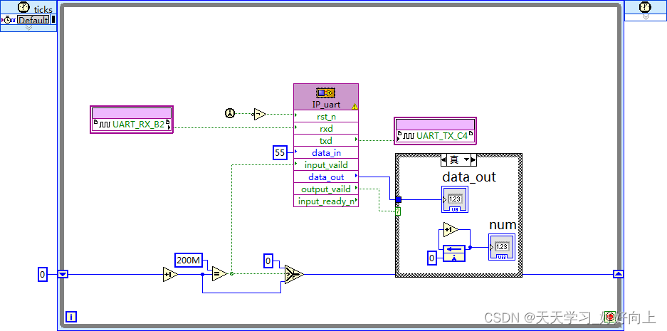
串口通信IP核除了包含之前环回实验的复位、RXD、TXD,还增加了数据的输入data_in和握手协议。为了验证其功能,我们在输出dataout增加了前面板显示控件以及计数控件,验证发送与接收功能,定时4秒发送一个0x55,验证IP核的发送功能。
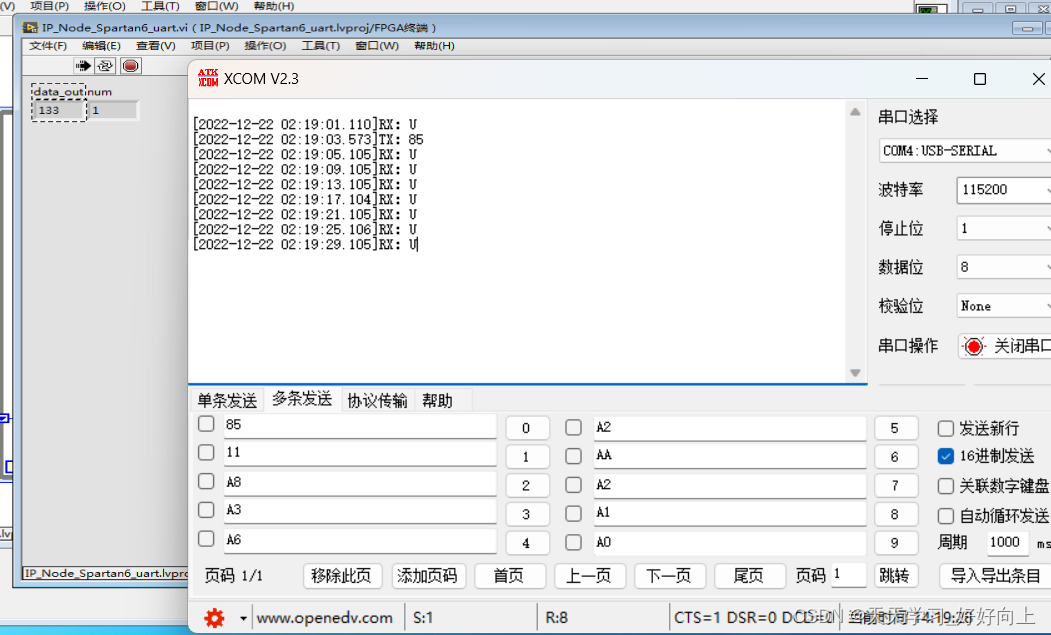
可以看到,发送一个0x85,接收到123,ASCII码中的U对应的是0x55,串口通信功能实现,之后需要在项目中用到串口通信功能的话,只需要在IP核上接FIFO就可以实现跨时钟域的通信功能了。
总结
FPGA图形化编程其优势在于逻辑图形化,若不去考虑底层verliog,在顶层设计上FPGA的图形化编程是有优势的,可以更有效率的完成FPGA的设计,本节实验的Verliog网表文件和LabVIEW的vi均开源在 我的资源 如有需要可以下载学习。


 1528
1528

 被折叠的 条评论
为什么被折叠?
被折叠的 条评论
为什么被折叠?
 到【灌水乐园】发言


