


PCIe总线是用来取代PCI总线的新型串行总线协议。这个与将要设计的串行解串器类似。对于利用串行解串器来进行数据传输的两个系统,要发送的数据会先被保存下来,然后被送入到一个缓冲区内(即FIFO),接着,它们被串行化,然后一个一个比特地被发送给目标系统。在接收端,输入的串行数据被解串,然后再次保存到缓冲区内,并按照并行的格式被发送到接收系统的并行总线上,为了实现数据的同步,接收端必须从接收的串行数据中提取出数据的有效时钟信息。这里的时钟其实和接收数据的帧边界其实是同一个概念,整个串行/解串器的结构如图所示:

先从时钟源设计开始:
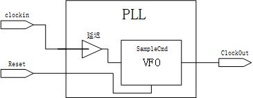
一个典型的锁相环(PLL)由以下三部分构成:输出时钟产生器,可变频率振荡器(VFO)。PLL会比较输入时钟相位和VFO时钟的差别,并根据这个差别来调整VFO产生的时钟的频率,其原理图如下:
我们用目标库中速度最快的延迟单元来完成 这个可以工作很高时钟下的振荡器的设计,在verilog方面主要体现在以下两方面:1.用generate来表示线延迟;2.添加DC的set_dont_touch来阻止综合工具把我们认为增加的线延迟给优化掉;

把这个振荡器命名为FsatClock,并作为时钟驱动计数器,把计数器的门限值VaryFreq,用来控制VFO的时钟频率。
VFO的内部的比较器将计数值与计数器的溢出门限值VaryFreq相比较,当计数值达到门限值,计数器被复位。

以上我们可以得到一个32x的PLL,32xPLL受到1MHz的时钟驱动,并且采样VFO的PLL输出。设置两个计数器,一个是被外部的PLL1MHz的输入时钟驱动,另一个是被PLL内部的P1MHZ的溢出计数器产生的时钟驱动,每个时钟到来时把计数值进行比较,从而得到两个时钟的相对关系。只要两个计数值不相等就会去调整VFO的频率。这两个2比特的计数器对32xPLL Muounter计数器产生时钟输出连续计数,在每一个PLL时钟的上升沿,对应边沿的计数值都用来做比较,从而产生乐调整VFO且及时更新的调整量。模块Zeroer不断检测ClockIn的计数值,当计数值为3时,计数器同时清零。

模块的代码如下:
1.Top
module PLLTop (output ClockOut, input ClockIn, Reset);
//
wire[1:0] AdjFreq;
wire MHz32, CtrCarry;
//
// -----------------------------------------------
// The new sample edge generator:
wire SampleWire;
//
DEL005 SampleDelay1 (.Z(SampleWire), .I(ClockIn));
//
//synopsys dc_tcl_script_begin
// set_dont_touch SampleDelay1
// set_dont_touch SampleWire
// set_dont_touch ClockIn
//synopsys dc_tcl_script_end
//
// -----------------------------------------------
assign ClockOut = MHz32;
//
ClockComparator
Comp1 ( .AdjustFreq(AdjFreq), .ClockIn(ClockIn)
      , .CounterClock(CtrCarry), .Reset(Reset)
      );
//
VFO
VFO1 ( .ClockOut(MHz32), .AdjustFreq(AdjFreq)
     , .Sample(SampleWire), .Reset(Reset)
     );
//
MultiCounter
MCntr1 (.CarryOut(CtrCarry), .Clock(MHz32), .Reset(Reset));
//
endmodule // PLLTop.
//
2.VFO
// The timescale and VFO_MaxDelta from the Deserializer
// design are used in VFO:
//
`include "SerDes.inc"
//
// ---------------------------------------------------
// The empirical frequency-setting parameters:
// DivideFactor is the number of fast-counter increments
// per PLL output clock.   Thus, PLL output period is
// given by: T = 2*DivideFactor*ElemDelay, in which,
//
// ElemDelay = DelayElementAvgDelay
//
// ElemDelay is estimated in ns, averaged over rise &
// fall, and it is used in VCS message calculations as
// well as VFO frequency limit stops.
//
// ---------------------------------------------------
// The next macro configures the FastClock oscillator and
// FastDivvy counter (2 elems probably is too fast for
// DEL005 and 90-nm Typical gates):
//
`define NumElems  5      // Delay line length.
//
// ---------------------------------------------------
// We use the PLL multiplication factor, 32, to set the
// initial DivideFactor.
// We want to divide the frequency, and the delay line
// just gives edge delays, so the initial divide factor
// should be about 1/4 the PLL multiplication factor:
//
`define ElemDelay 0.0850 // Delay element avg. delay.
`define DivideFactor 32.0/(4.0*`NumElems*`ElemDelay)
//
// NFastBits will be calculated to ensure that the
// frequency initialization value (`DivideFactor) will
// be less than the maximum value of the FastDivvy and
// DivideFactor regs declared below.
// ---------------------------------------------------
module VFO (output ClockOut, input[1:0] AdjustFreq
           , input Sample, Reset
           );
reg    ClockOutReg;
assign ClockOut = ClockOutReg;
//
// Configure the fast clock counter:
localparam NFastBits =
                     (`DivideFactor < (2**3 - (`VFO_MaxDelta/(2.0*`ElemDelay) + 1)) )? 3
                   : (`DivideFactor < (2**4 - (`VFO_MaxDelta/(2.0*`ElemDelay) + 1)) )? 4
                   : (`DivideFactor < (2**5 - (`VFO_MaxDelta/(2.0*`ElemDelay) + 1)) )? 5
                   : (`DivideFactor < (2**6 - (`VFO_MaxDelta/(2.0*`ElemDelay) + 1)) )? 6
                   : (`DivideFactor < (2**7 - (`VFO_MaxDelta/(2.0*`ElemDelay) + 1)) )? 7
                   : (`DivideFactor < (2**8 - (`VFO_MaxDelta/(2.0*`ElemDelay) + 1)) )? 8
                   : 9;
//
localparam[NFastBits-1:0] DivideLoLim = `DivideFactor - `VFO_MaxDelta;
localparam[NFastBits-1:0] DivideHiLim = `DivideFactor + `VFO_MaxDelta;
//
// Assertions:
`ifdef DC
`else
initial
  begin
  $display("VFO FastClock delay chain: %0.0f cells @%1.4f ns; f divider=[%0.0f] bits.\n"
          ,                          `NumElems, `ElemDelay,         NFastBits
          );
  $display("VFO divide factor=%0.0f; so, initial SYNTH 1 MHz in => %2.1f MHz out.\n"
          ,       `DivideFactor, 1000.0/32.0
          );
  $display("`VFO_MaxDelta=[%0.0f] => Divider limits: Low Lim=%0.0f and High Lim=%0.0f.\n"
          , `VFO_MaxDelta,                           DivideLoLim,          DivideHiLim
          );
  end
`endif
//
// ---------------------------
最低0.47元/天 解锁文章


 5683
5683


 被折叠的 条评论
为什么被折叠?
被折叠的 条评论
为什么被折叠?
 到【灌水乐园】发言


