


Real-time-speed-regulation-of-DC-motor
Introduction
The motor system can generate different disturbances through a knob. To make the system quickly recover to the target speed after the disturbance, the parameters are determined by Matlab, and PID control module is realized based on MSP430. In addition, different target speeds can be set by the button.
TimerA0 is used to generate the interrupts, and the incremental encoder is used to calculate the DC motor speed, which is displayed through the 7-segment digital tube. TimerA1 is used to generate PWM signal as motor input.
Mapping table
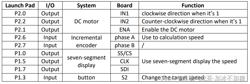
The strategy of measuring the speed
According to the principle of the incremental encoder, it outputs 3 pulse for every revolution. We can use the MSP430’s internal timer and set it to trigger an interrupt every 0.1 seconds, capturing the total number of input pulses at P2.6/P2.7 in this period, thus converting the speed of the motor.
In addition, pulses on P2.6 and P2.7 can be measured simultaneously, and the phase difference between them determines the direction of rotation of the motor.
Function
port_init
Initialize the pins. Including.
- Set P2.1 ~ P2.2 as output.
- Set P2.6 as GPIO input. P2.6 is the phase A of the incremental encoder. Use pull-down resistor and enable the interrupt.
- Set P1.3 as GPIO input. P1.3 is a button. Use pull-down resistor and enable the interrupt.
timer_init
Initialize the timer. Use TimerA_0 to create interrupts and count the pulse number num every 0.1 seconds.
- SMCLK = 1MHz, DIV = 2.
- Up mode.
- Set the timer interrupt per 0.1 seconds.
pwm_init
Initialize the PWM.
- Set P2.1 as Timer1_A3.TA1.
- Set P2.2 as primary peripheral module function. Use TimerA_1 to create PWM as the input of DC motor.
- SMCLK = 1MHz, DIV = 1.
- Up mode.
- Output mode 7.
- The duty ratio = 35%.
PID_controller
When the disturbance occurs, it will work to return to the desired speed. Adjust the output PWM according to the speed feedback from the encoder.
The parameters of PID controller:
- Kp = 0.00002
- Ki = 0.000008
- Kd = 0.000001
affiche_Vitesse(speed)
Display the speed Vitesse.
TIMER1_A0_ISR
Calculation speed when interrupt happens. speed = (num/3)1060. Call the PID control and display the speed. Clear interrupt flag.
TIMER1_A1_ISR
Clear interrupt flag.
PORT2_ISR
The interruption occurs at each pulse edge of the sensor on the motor. Add num for each interrupt to measure the speed. Clear interrupt flag.
PORT1_ISR
An interrupt occurs when the button is pressed. Change the button value between [0,2]. Clear interrupt flag.
main
Change the target speed according to the value of button. Three different target speeds are set: 3000, 4800, 6000.
Code
#include <msp430.h>
#include "Library_Display.h"

#define SPEED0 3000
#define SPEED1 4800
#define SPEED2 6000

/**************************************************************/
/*                   Variable Declaration                     */
/**************************************************************/
// PID controller parameters
float Kp = 0.00002;
float Ki = 0.000008;
float Kd = 0.000001;

// PID controller variable
float error1 = 0, error0 = 0;
float pn = 0, in = 0, i0 = 0, dn = 0;
float un = 0, vn = 0;

// calculate DC motor speed
int num = 0;                        // number of interrupts in P2.6 per 0.1s
int speed = 0;                      // current speed
int desired_speed = SPEED0;         // desired speed
int button = 0;                     // choose the desired speed


/**************************************************************/
/*                   Function Declaration                     */
/**************************************************************/
void port_init();
void timer_init();
void pwm_init();
void PID_controller();

/**************************************************************/
/*                 Function Implementation                    */
/**************************************************************/

/* Initialize the pins */
void port_init(){
    /* P2.0 ~ P2.2:     output      DC motor                            */
    P2DIR |= BIT1;                  // set as output
    P2DIR |= BIT2;                  // set as output

    /* P2.6:            input       phase A of the incremental encoder  */
    P2SEL  &= ~BIT6;
    P2SEL2 &= ~BIT6;                // set as GPIO
    P2DIR  &= ~BIT6;                // set as input
    P2REN  |= BIT6;                 // resistor enabled
    P2OUT  &= ~BIT6;                // set pull-down resistor
    P2IES  &= ~BIT6;                // select interrupt edge low-to-high transition
    P2IE   |= BIT6;                 // interrupt enable
    P2IFG  &= ~BIT6;                // clear interrupt flag

    /* P1.3:            input       button to change the desired speed  */
    P1SEL  &= ~BIT3;
    P1SEL2 &= ~BIT3;                // set as GPIO
    P1DIR  &= ~BIT3;                // set as input
    P1REN  |= BIT3;                 // resistor enabled
    P1OUT  |= BIT3;                 // set pull-down resistor
    P1IES  |= BIT3;                 // select interrupt edge low-to-high transition
    P1IE   |= BIT3;                 // interrupt enable
    P1IFG  &= ~BIT3;                // clear interrupt flag
}

/* Initialize the timer. Use TimerA_0 to create interrupts and count the number */
void timer_init(){
    /* TimerA_0:        to create interrupts and count the number       */
    TA0CTL = 0;
    TA0CTL |= TASSEL_2 | ID_1;      // SMCLK = 1MHz, DIV = 2
    TA0CTL |= MC_1;                 // Up mode
    TA0CTL |= TAIE;                 // interrupt enable
    TA0CTL &= ~TAIFG;               // clear interrupt flag
    TA0CCR0 = 50000;                // count up to 50000 (0.1s)
}

/* Initialize the PWM. Use TimerA_1 to create PWM */
void pwm_init(){
    /* P2.1:            output      DC motor Enable                     */
    P2SEL  |= BIT1;
    P2SEL2 &= ~BIT1;
    P2DIR  |= BIT1;                 // set as Timer1_A3.TA1

    /* P2.2:            output      DC motor IN2                        */
    P2SEL  |= BIT2;
    P2SEL2 &= ~BIT2;                // set as primary peripheral module function
    P2DIR  |= BIT2;                 // set as output

    /* TimerA_1:        to create PWM                                   */
    TA1CTL = 0;
    TA1CTL |= TASSEL_2 | ID_0;      // SMCLK = 1MHz, DIV = 1
    TA1CTL |= MC_1;                 // Up mode
    TA1CCTL1 |= OUTMOD_7;           // set output mode 7
    TA1CCR0 = 20000;
    TA1CCR1 = 7000;                 // the duty ratio = 35%
}

/* PID controller. When the disturbance occurs, it will return to the desired speed  */
void PID_controller(){
    error1 = desired_speed - speed;
    pn = Kp * error1;
    in = i0 + Ki * error1;
    dn = Kd * (error1 - error0);
    vn = pn + in + dn;
    if (vn > 1){
        un = 1;
    }else if(vn < 0){
        un = 0;
    }else{
        un = vn;
    }
    in = in + un - vn;
    error0 = error1;
    i0 = in;
    TA1CCR1 = un * TA1CCR0;
}


/**************************************************************/
/*                     The Main Function                      */
/**************************************************************/
int main(void){
	WDTCTL = WDTPW | WDTHOLD;	    // stop watchdog timer
	DCOCTL = CALDCO_1MHZ;
	BCSCTL1 = CALBC1_1MHZ;

	port_init();                    // initialize the pins
	timer_init();                   // initialize the timer
	pwm_init();                     // initialize the pwm
    Display_Init();                 // display the speed
    affiche_Vitesse(speed);         // display the speed
    __enable_interrupt();           // enable global interrupt

	while(1){
	    switch (button){            // change the target speed according to the value of button
	    case 0:
	        desired_speed = SPEED0;
	        break;
	    case 1:
	        desired_speed = SPEED1;
	        break;
	    case 2:
	        desired_speed = SPEED2;
	        break;
	    default:
	        break;
	    }
	}
}

/**************************************************************/
/*              Interruptive Service Routine                  */
/**************************************************************/

#pragma vector = TIMER0_A1_VECTOR
__interrupt void TIMER1_A0_ISR(void){
    speed = (num/3)*10*60;          // calculation speed
    num = 0;                        // clear the num
    PID_controller();               // PID control
    affiche_Vitesse(speed);         // display the speed
    P2IFG |= BIT6;
    TA0CTL &= ~TAIFG;               // clear interrupt flag
}

#pragma vector = TIMER1_A1_VECTOR
__interrupt void TIMER1_A1_ISR(void){
    TA1CTL &= ~TAIFG;               // clear interrupt flag
}

#pragma vector = PORT2_VECTOR
__interrupt void PORT2_ISR(void){
    num++;                          // add num for each interrupt
    P2IFG &= ~BIT6;                 // clear interrupt flag
}

#pragma vector = PORT1_VECTOR
__interrupt void PORT1_ISR(void){
    button = (button+1)%2;          // button value between [0,2]
    P1IFG &= ~(BIT3);               // clear interrupt
}


 678
678

 被折叠的 条评论
为什么被折叠?
被折叠的 条评论
为什么被折叠?
 到【灌水乐园】发言


