


前言
相比普通相机,双目相机通过模拟人眼视差的原理,可以同时获取两张略有偏差的图像,从而计算出物体到相机的距离。为了让双目系统具备准确的测距能力,首先需要对相机进行标定,确定其内外参数。完成标定后,我们就可以利用视差计算深度图,进一步生成真实世界的三维点云,实现空间结构的可视化和感知。
下载标定代码
之前使用过matlab中的stereo camera calibrator做过双目相机的标定,但是效果并不好,所以使用opencv完成。因为后续我是使用cv作为双目图像计算的工具,就算matlab标定的结果是正确的,也需要将matlab的标定结果手动输入至cv的代码中,这其中可能涉及到计算和转换,所以不如一开始就是用cv2.stereoCalibrate()完成标定。
首先下载github代码:
git clone https://github.com/shubhamwagh/stereo-calib这是我找到的比较好的基于cv2的一键式标定。
再根据readme安装好所需环境,这里建议先使用anaconda新建一个环境,因为直接安装的话可能系统的python版本可能不够高,这里需要python>=3.9:
conda create -n stereo-310 python=3.10
pip install poetry
cd stereo-calib
poetry config virtualenvs.in-project true
poetry install
之后需要使用open3d显示点云,所以也安装一下:
pip install open3d -i https://pypi.tuna.tsinghua.edu.cn/simple安装好环境之后可以试试能不能跑,作者在dataset中带了自己的图片,所以可以直接尝试标定,实测可以用pycharm直接运行或调试,不一定要用命令行:
poetry run python -m examples.perform_calibration --data-path "./dataset" 准备一组双目图像
在配环境的过程中,打开项目中的dataset文件夹,找到其中的pdf,打印这个标定照片,readme上说最好打印a1,但是实测a4也可以,打印好之后查看一下清晰度,之后使用电脑自带的“相机”或者用代码拍摄都可以,拍摄过程中注意:和普通的棋盘格不同,这个带有aruco的棋盘格可以拍得不完全,也就是每张照片带有部分棋盘格即可,强行拍整幅a4可能会导致里面的aruco模糊。图片的格式最好是png,这样不用改代码,jpg后续也就是在代码中改三个字母即可,以下是我的示例:
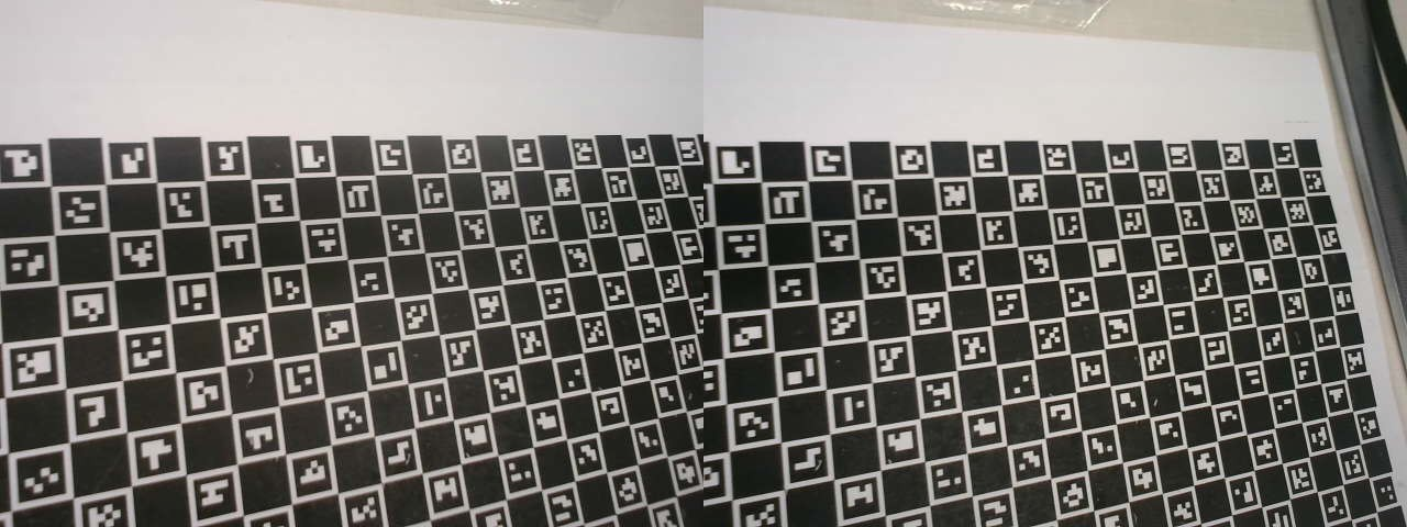
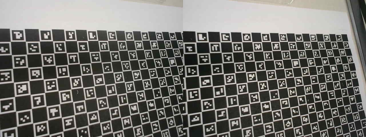
我的双目相机拍完之后是拼接好的,所以需要裁切一下,但是首先先把图片放入项目的./dataset/all中,同时还需要把作者的left和right的图片都删了。
pic_cut.py
import os
import cv2

# 输入文件夹和输出子文件夹路径
input_dir = './dataset/all'
left_dir = './dataset/left'
right_dir = './dataset/right'

# 创建输出目录(如果不存在)
os.makedirs(left_dir, exist_ok=True)
os.makedirs(right_dir, exist_ok=True)

# 获取所有 .jpg 文件并排序
image_files = sorted([f for f in os.listdir(input_dir) if f.lower().endswith('.jpg')])

# 遍历并处理图像
for idx, filename in enumerate(image_files, start=1):
    filepath = os.path.join(input_dir, filename)
    image = cv2.imread(filepath)

    if image is None:
        print(f"❌ 读取失败: {filename}")
        continue

    h, w = image.shape[:2]
    mid = w // 2

    left_img = image[:, :mid]
    right_img = image[:, mid:]

    left_path = os.path.join(left_dir, f"L_{idx}.jpg")
    right_path = os.path.join(right_dir, f"R_{idx}.jpg")

    cv2.imwrite(left_path, left_img)
    cv2.imwrite(right_path, right_img)

    print(f"✅ 已保存: {left_path}, {right_path}")

print("🎉 所有图片分割并重命名完成!")
直接用我的代码没问题,如果是自己写的或者其他方式得到的左右图片的命名要注意,索引一定要在最后,比如L_0.jpg而不是0_L.jpg,不然后续代码会报错。
图片格式为jpg的同学请把.\stereo_calib\calibration\camera_calibrate.py代码中的.png改为jpg,这样就不会出错了。
生成标定结果
需要根据实际打印的棋盘格大小调整一下.\stereo_calib\charuco\constants.py中的参数,就只要改两个length即可。这是我量的,可能不太精确。
SQUARE_LENGTH: float = 0.00900
MARKER_LENGTH: float = 0.00630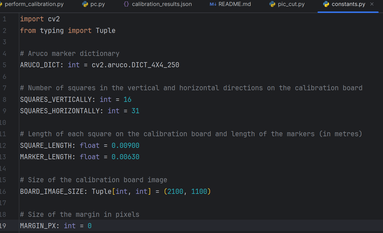
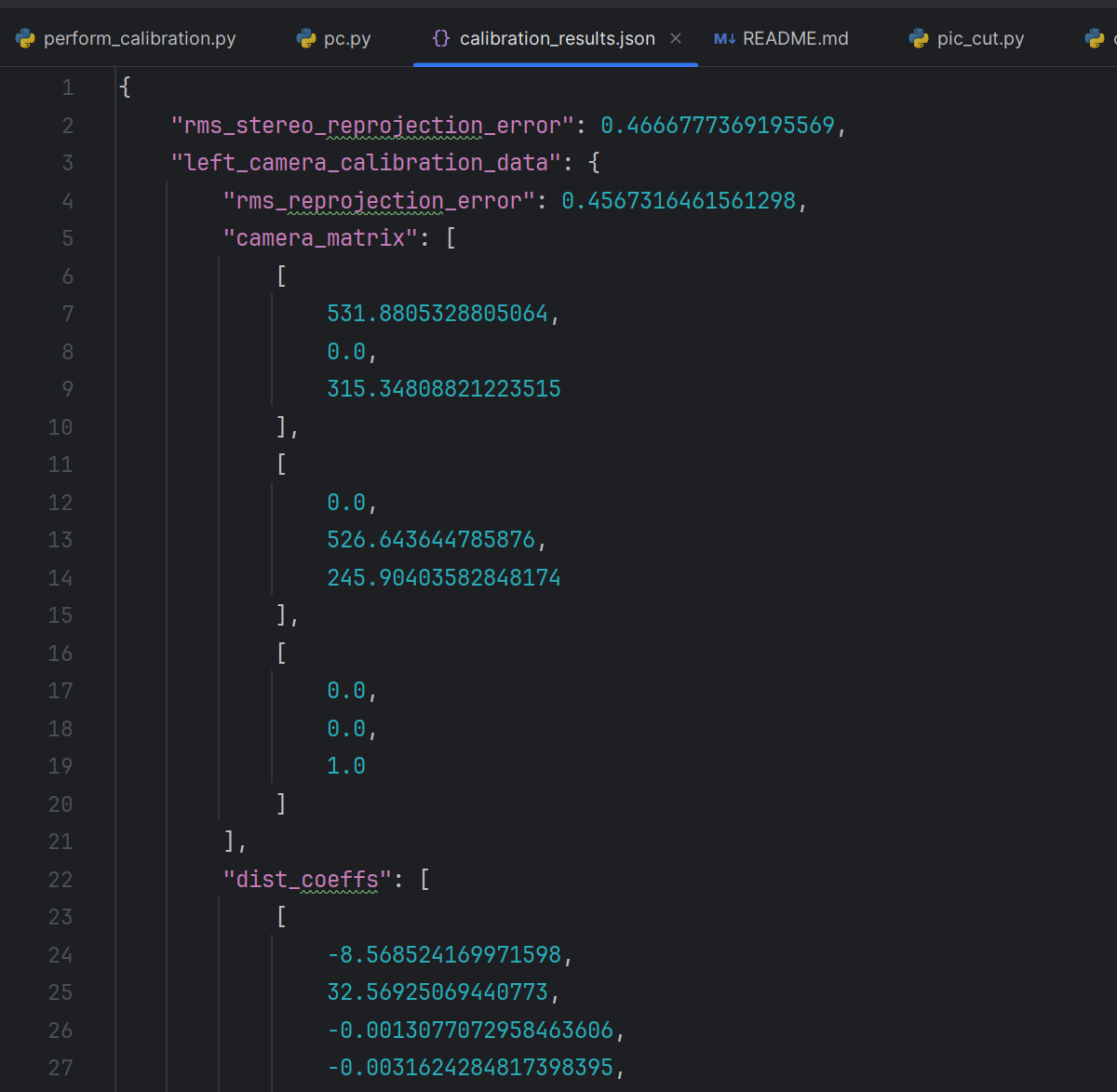
运行perform_calibration.py,等读条完毕,没有报错的话即可得到json格式的标定结果,各种变换矩阵和参数在.\results\calibration_results.json中。
生成深度图和点云
作者其实在完成标定后直接生成过深度图,也在results文件夹中,所以基于他的改一下即可,这里注意一下cap = cv2.VideoCapture(0, cv2.CAP_DSHOW),有些相机是cap = cv2.VideoCapture(0),拿不准就调试一下:
pc.py
import cv2
import numpy as np
import open3d as o3d
from pathlib import Path
from stereo_calib.utils.calibration_utils import load_calibration_data
from stereo_calib.utils.stereo_utils import compute_disparity, compute_depth_map
from typing import Tuple


def cut_stereo_image(stereo_img: np.ndarray) -> Tuple[np.ndarray, np.ndarray]:
    """
    将拼接后的双目图像切割成左图和右图。
    """
    height, width = stereo_img.shape[:2]
    mid = width // 2
    left_img = stereo_img[:, :mid]
    right_img = stereo_img[:, mid:]
    return left_img, right_img


def generate_point_cloud(disparity, image_left, Q):
    points_3d = cv2.reprojectImageTo3D(disparity, Q)
    mask = disparity > 0
    points = points_3d[mask]
    colors = image_left[mask]

    # 创建 Open3D 点云
    pcd = o3d.geometry.PointCloud()
    pcd.points = o3d.utility.Vector3dVector(points)
    pcd.colors = o3d.utility.Vector3dVector(colors / 255.0)
    return pcd


# ====== 1. 加载标定参数 ======
calib_data = load_calibration_data("results/calibration_results.json")
Q = calib_data.perspective_transformation_matrix_Q

# ====== 2. 打开拼接图像的双目相机 ======
cap = cv2.VideoCapture(0, cv2.CAP_DSHOW)
cap.set(cv2.CAP_PROP_FRAME_WIDTH, 1280)
cap.set(cv2.CAP_PROP_FRAME_HEIGHT, 480)

# ====== 4. 实时处理循环(只显示深度图) ======
latest_disparity = None
latest_color = None

while True:
    ret, frame = cap.read()
    if not ret:
        print("无法读取图像")
        break

    # 切出左右图
    frame_l, frame_r = cut_stereo_image(frame)
    gray_l = cv2.cvtColor(frame_l, cv2.COLOR_BGR2GRAY)
    gray_r = cv2.cvtColor(frame_r, cv2.COLOR_BGR2GRAY)

    # 计算视差和深度
    disparity = compute_disparity(gray_l, gray_r, min_disparity=8, num_disparity=16 * 6)
    depth = compute_depth_map(disparity, Q)

    # 可视化深度图
    depth_vis = cv2.applyColorMap(cv2.convertScaleAbs(depth, alpha=255 / np.max(depth)), cv2.COLORMAP_JET)
    cv2.imshow("Depth", depth_vis)

    # 保存最后一帧的视差图和彩色图
    latest_disparity = disparity.copy()
    latest_color = frame_l.copy()

    # 若 OpenCV 窗口被关闭(返回值为 -1),或按下 ESC 键,则退出循环
    if cv2.getWindowProperty("Depth", cv2.WND_PROP_VISIBLE) < 1:
        break
    if cv2.waitKey(1) & 0xFF == 27:
        break


# ====== 5. 用 Open3D 显示最后一帧点云 ======
if latest_disparity is not None and latest_color is not None:
    points_3d = cv2.reprojectImageTo3D(latest_disparity, Q)
    mask = latest_disparity > 0
    points = points_3d[mask]
    colors = latest_color[mask]

    pcd = o3d.geometry.PointCloud()
    pcd.points = o3d.utility.Vector3dVector(points)
    pcd.colors = o3d.utility.Vector3dVector(colors / 255.0)

    o3d.visualization.draw_geometries([pcd], window_name="Final Point Cloud")


# ====== 6. 清理资源 ======
cap.release()
cv2.destroyAllWindows()
在cv2界面可以看到实时更新的深度图,按ESC后即可看到open3d点云。


 481
481

 被折叠的 条评论
为什么被折叠?
被折叠的 条评论
为什么被折叠?
 到【灌水乐园】发言


