


PMLAB X IDE软件入门
1 建立 工程
1.2 新建工程
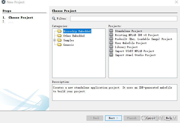
1、单击file—new project----单击standalone project—点击next
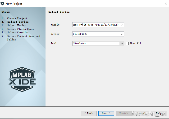
2、family选择第四个,Mid-Range 8-bit MCUs (PIC10/12/16/MCP);
device选择PIC12F1822;
tool选择simulator(或者ICD4)。
然后点击next。
需要注意的是,芯片选型必须正确,要不然和现有芯片符号不符,无法烧录程序。
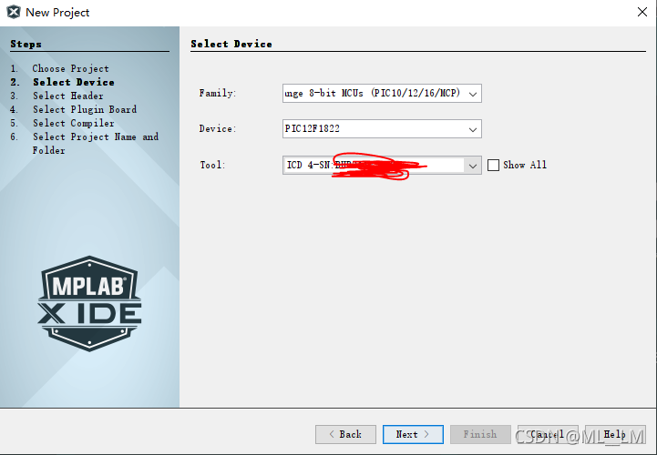
如果您具有调试器,并希望对硬件使用它,则从列表中选择该调试器(本说明为ICD4);
否则,请选择Simulator(软件模拟器)。
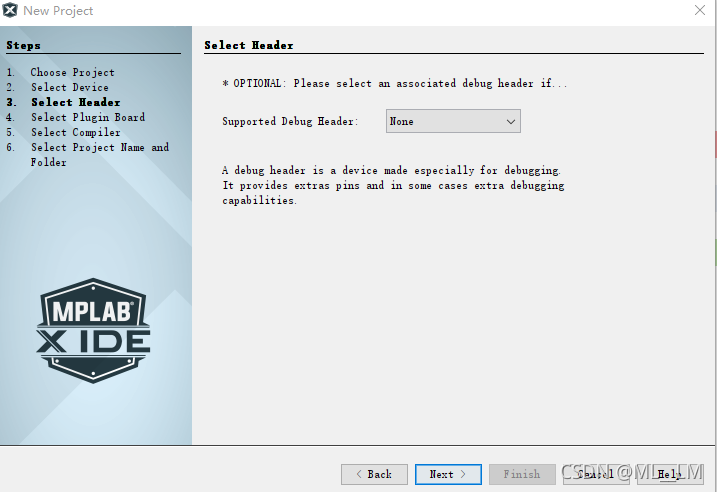
3、点击next
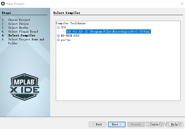
4、编译器选择 XC8,然后点击next。
需要注意的是,必须要先安装XC8,才会出现这个按钮。
XC8的安装包下载地址:
https://www.microchip.com/en-us/development-tools-tools-and-software/mplab-xc-compilers
5、project name:输入工程名字
project location:选择工程所在位置。
encoding:选择GB2312这一栏必须选择GB2312,否则注释里面的汉字无法识别。
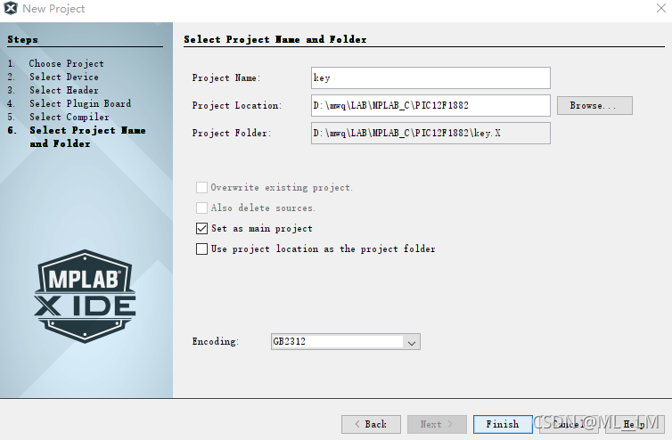
6、点击finish。
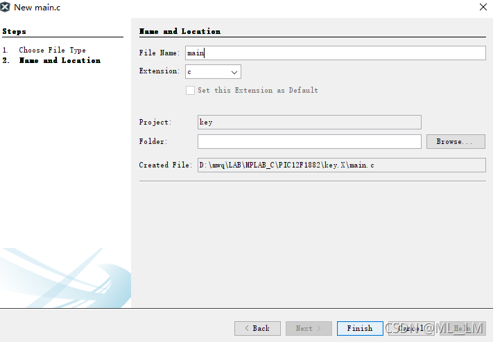
1.2 新建main.c文件
单击source files,右键,选择main.c。然后点击finish。
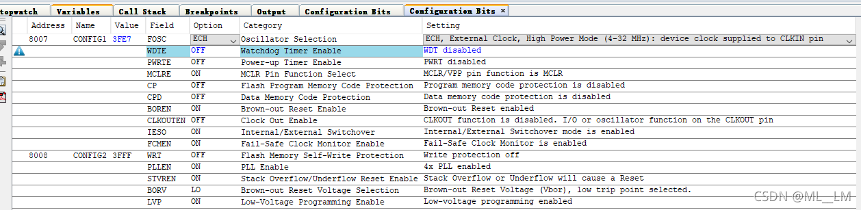
1.3 写配置字
单击production—set Configuration Bit----点击 generate source code to output ----复制生成内容到main函数
// PIC12LF1822 Configuration Bit Settings

// 'C' source line config statements

// CONFIG1
#pragma config FOSC = ECH       // Oscillator Selection (ECH, External Clock, High Power Mode (4-32 MHz): device clock supplied to CLKIN pin)
#pragma config WDTE = OFF       // Watchdog Timer Enable (WDT disabled)
#pragma config PWRTE = OFF      // Power-up Timer Enable (PWRT disabled)
#pragma config MCLRE = ON       // MCLR Pin Function Select (MCLR/VPP pin function is MCLR)
#pragma config CP = OFF         // Flash Program Memory Code Protection (Program memory code protection is disabled)
#pragma config CPD = OFF        // Data Memory Code Protection (Data memory code protection is disabled)
#pragma config BOREN = ON       // Brown-out Reset Enable (Brown-out Reset enabled)
#pragma config CLKOUTEN = OFF   // Clock Out Enable (CLKOUT function is disabled. I/O or oscillator function on the CLKOUT pin)
#pragma config IESO = ON        // Internal/External Switchover (Internal/External Switchover mode is enabled)
#pragma config FCMEN = ON       // Fail-Safe Clock Monitor Enable (Fail-Safe Clock Monitor is enabled)

// CONFIG2
#pragma config WRT = OFF        // Flash Memory Self-Write Protection (Write protection off)
#pragma config PLLEN = ON       // PLL Enable (4x PLL enabled)
#pragma config STVREN = ON      // Stack Overflow/Underflow Reset Enable (Stack Overflow or Underflow will cause a Reset)
#pragma config BORV = LO        // Brown-out Reset Voltage Selection (Brown-out Reset Voltage (Vbor), low trip point selected.)
#pragma config LVP = ON         // Low-Voltage Programming Enable (Low-voltage programming enabled)

// #pragma config statements should precede project file includes.
// Use project enums instead of #define for ON and OFF.

#include <xc.h>
1.4 编写main函数
/*
 * File:   main.c
 * Author: Sure
 *
 * Created on November 13, 2021, 4:39 PM
 */

// PIC12F1822 Configuration Bit Settings

// 'C' source line config statements

// CONFIG1
#pragma config FOSC = ECH       // Oscillator Selection (ECH, External Clock, High Power Mode (4-32 MHz): device clock supplied to CLKIN pin)
#pragma config WDTE = OFF       // Watchdog Timer Enable (WDT disabled)
#pragma config PWRTE = OFF      // Power-up Timer Enable (PWRT disabled)
#pragma config MCLRE = OFF       // MCLR Pin Function Select (MCLR/VPP pin function is MCLR)
#pragma config CP = OFF         // Flash Program Memory Code Protection (Program memory code protection is disabled)
#pragma config CPD = OFF        // Data Memory Code Protection (Data memory code protection is disabled)
#pragma config BOREN = ON       // Brown-out Reset Enable (Brown-out Reset enabled)
#pragma config CLKOUTEN = OFF   // Clock Out Enable (CLKOUT function is disabled. I/O or oscillator function on the CLKOUT pin)
#pragma config IESO = OFF        // Internal/External Switchover (Internal/External Switchover mode is enabled)
#pragma config FCMEN = OFF       // Fail-Safe Clock Monitor Enable (Fail-Safe Clock Monitor is enabled)

// CONFIG2
#pragma config WRT = OFF        // Flash Memory Self-Write Protection (Write protection off)
#pragma config PLLEN = OFF       // PLL Enable (4x PLL enabled)
#pragma config STVREN = OFF      // Stack Overflow/Underflow Reset Enable (Stack Overflow or Underflow will cause a Reset)
#pragma config BORV = LO        // Brown-out Reset Voltage Selection (Brown-out Reset Voltage (Vbor), low trip point selected.)
#pragma config LVP = OFF         // Low-Voltage Programming Enable (Low-voltage programming enabled)

// #pragma config statements should precede project file includes.
// Use project enums instead of #define for ON and OFF.

#include <xc.h>


/*-----------子函数声明--------------*/
void delay_xms(int xms);


void main()
{

	//控制端口的方向为输出
	TRISA0=0;//方向控制寄存器(TRIS)D;1表示输入,0表示输出
	TRISA3=1;

    while(1)
    {
        RA0=0;
        if(RA3==0)
        {
            RA0=1;//端口控制寄存器(PORT)D;1表示高电平,0表示低电平  RD0=1
            delay_xms(500);

            RA0=0;
            delay_xms(500);
        }
    }

}


/*----------------------延时函数---------------------------------------------
关于取值大小:这个如果是在C下变成,这个值不仅仅与晶振、单片机本身运算速度有关,
而且还与C的编译器有关,所以说,这个值虽说是可以精确计算的,
但大多数情况下,程序员用的都是“经验值”。
如果用汇编编程,情况就不一样了,因为每一条指令所使用的机器周期是一定的,
你当然可以根据所有指令使用的总时间,精确的算出具体延时的总时间
--------------------------------------------------------------*/
void delay_xms(int xms)
{
	int i,j;
    for(i=xms;i>=0;i--)
	for(j=110;j>=0;j--);
}
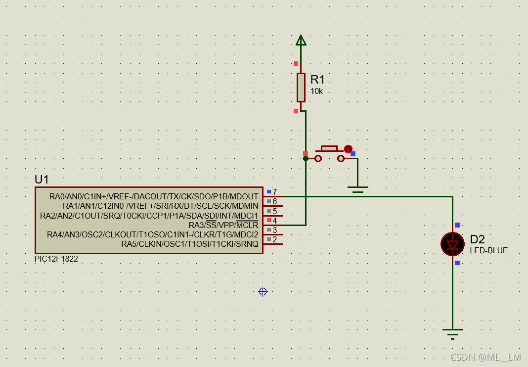
开关这里一定要有上拉电阻,否则功能不正常。
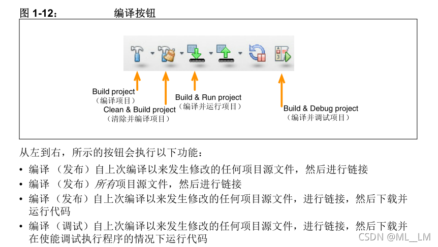
2 编译代码的常见工具栏
2.1 调试代码

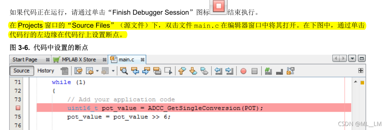
2.1.1 设置断点
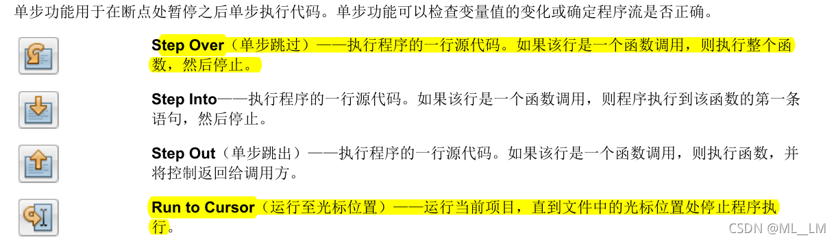
2.1.2 单步执行代码
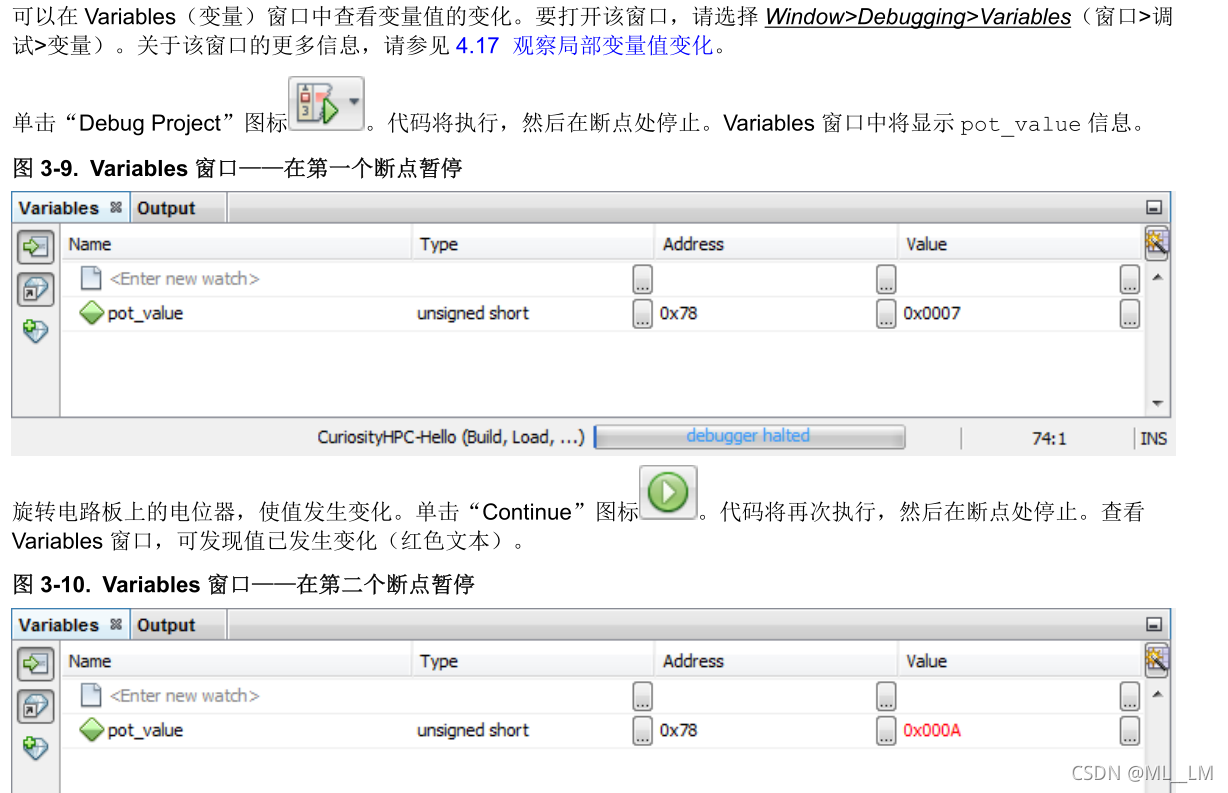
2.1.3 查看变量值
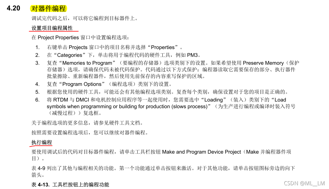
3 器件编程
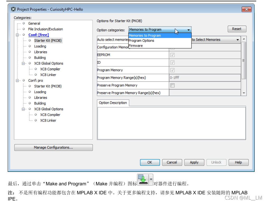
调试完代码之后,可以将它编程到目标器件上。
首先,在 Project Properties 窗口中检查编程选项。对于本教程,无需更改任何选项


 3030
3030

 被折叠的 条评论
为什么被折叠?
被折叠的 条评论
为什么被折叠?
 到【灌水乐园】发言


