


文章目录
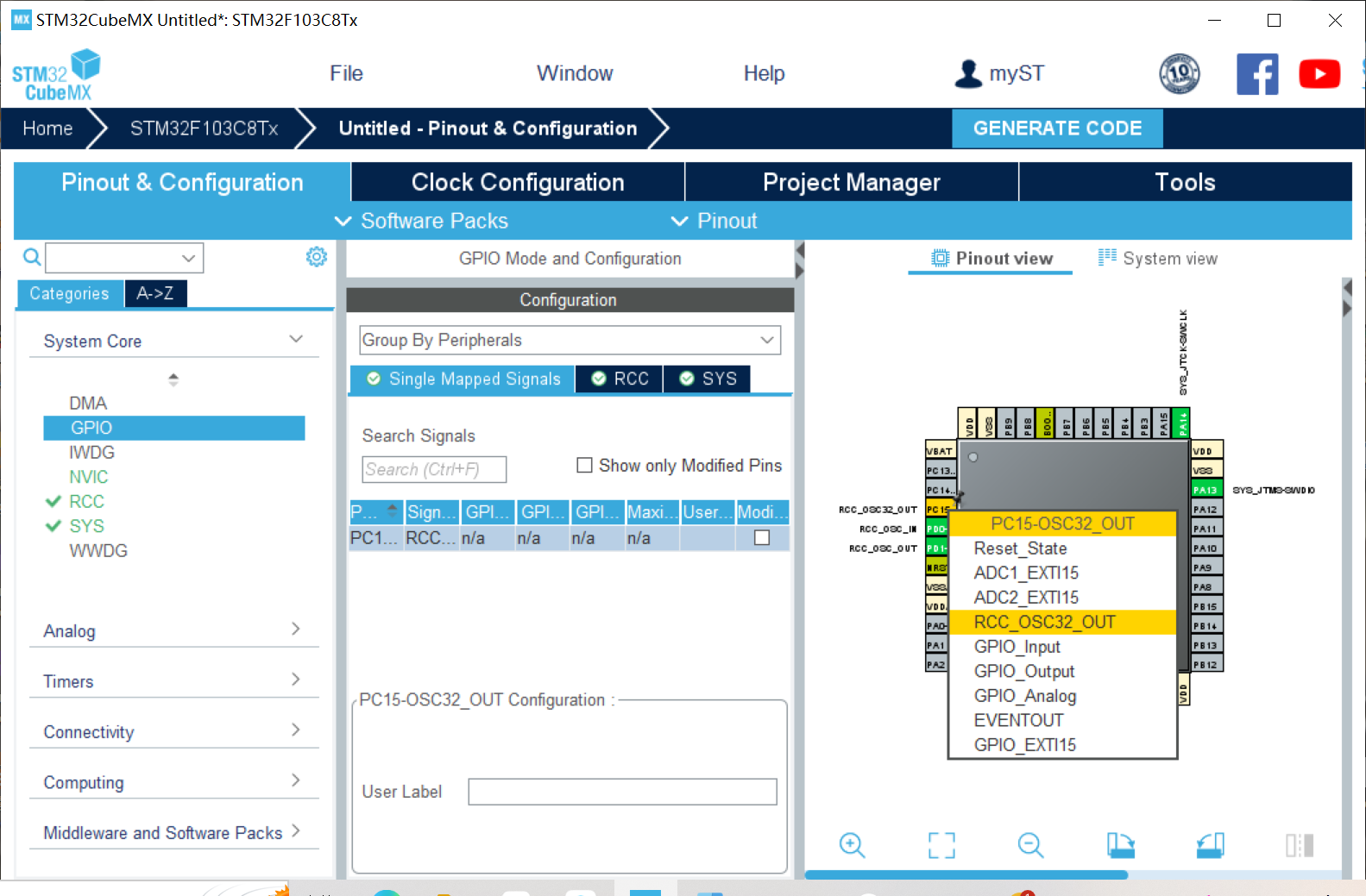
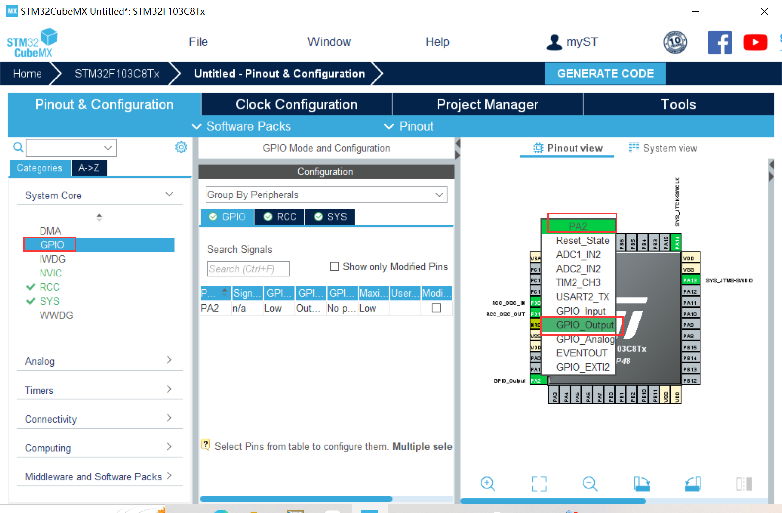
一、使用STM32F103的 Tim2~Tim5其一定时器的某一个通道pin(与GPIOx管脚复用,见下图),连接一个LED,用定时器计数方式,控制LED以2s的频率周期性地亮-灭。
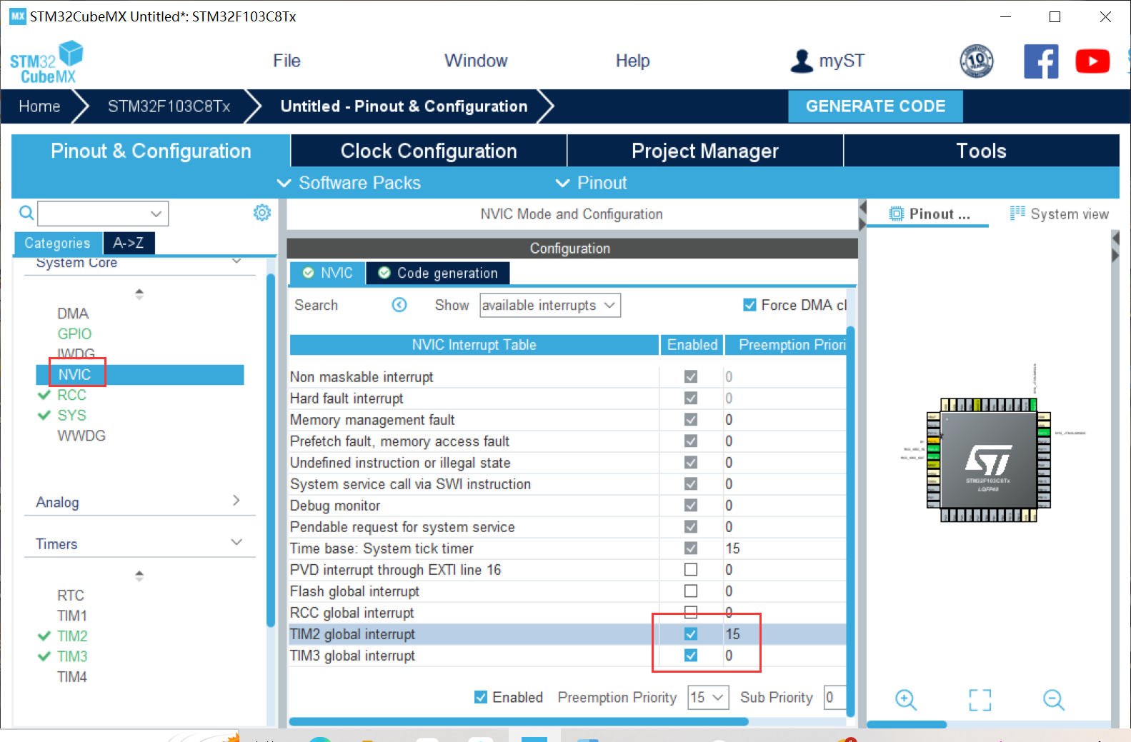
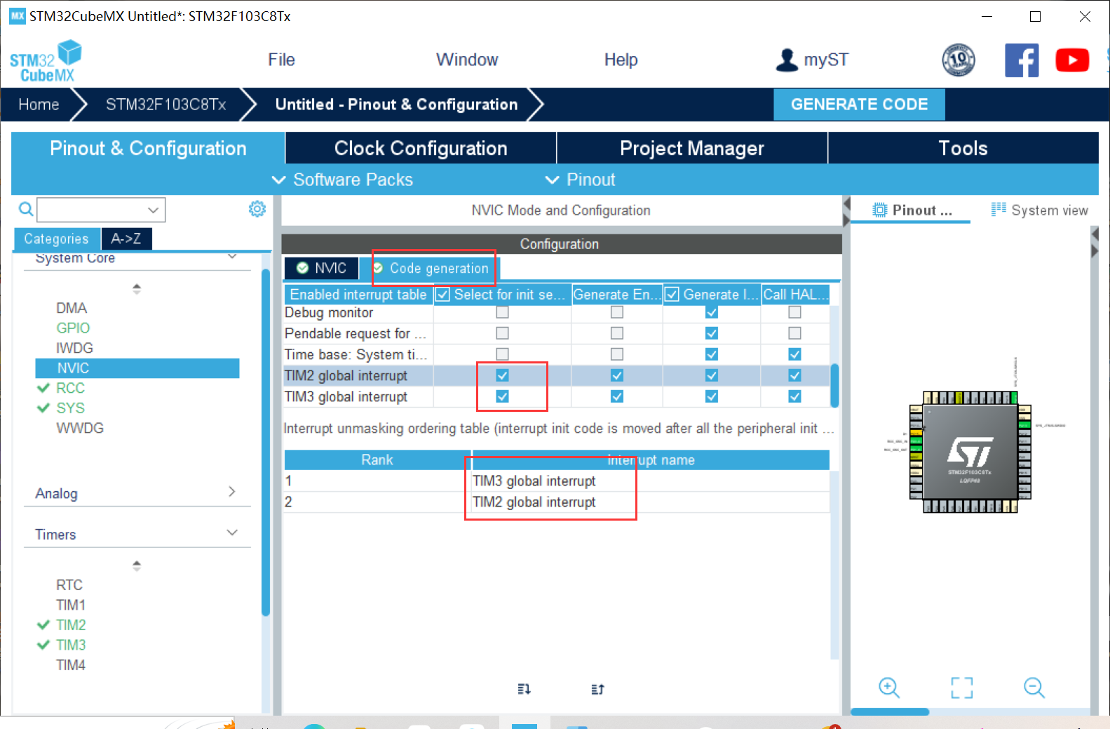
(一)STM32CubeMX配置


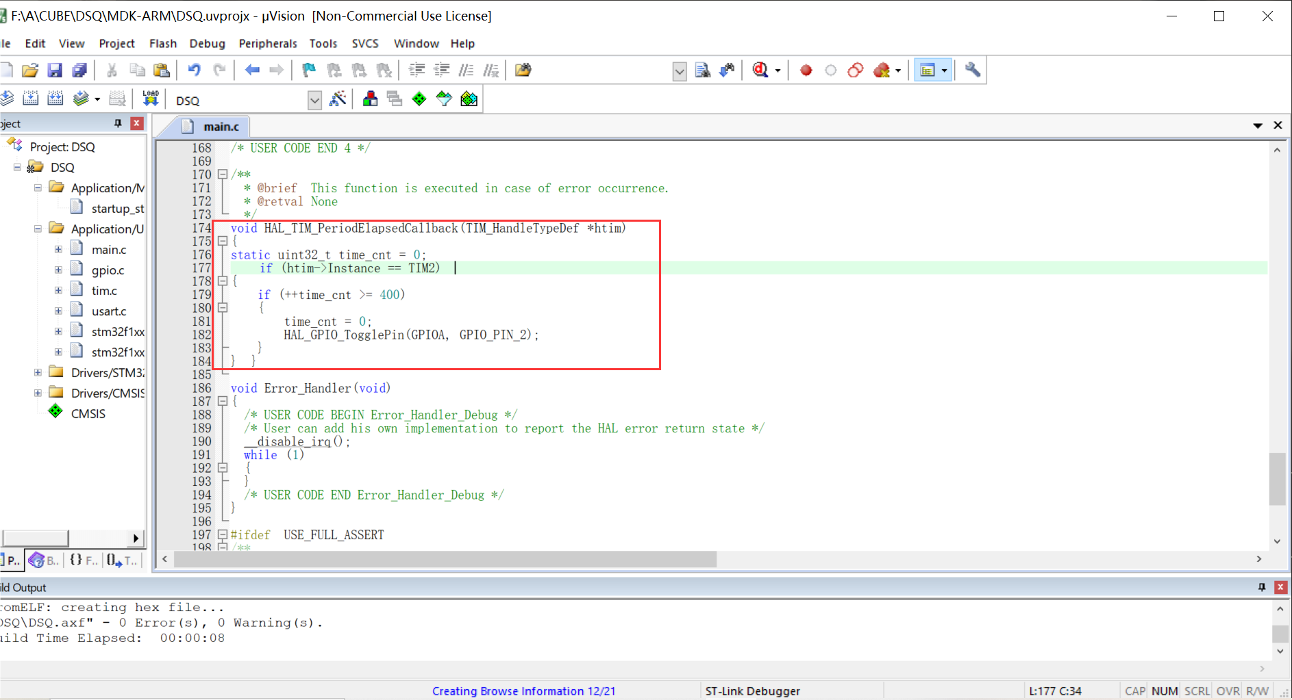
(二)keil写入代码
(三)烧录

二、接上,采用定时器pwm模式,让 LED 以呼吸灯方式渐亮渐灭,周期为1~2秒,自己调整到一个满意效果。使用Keil虚拟示波器,观察 pwm输出波形。
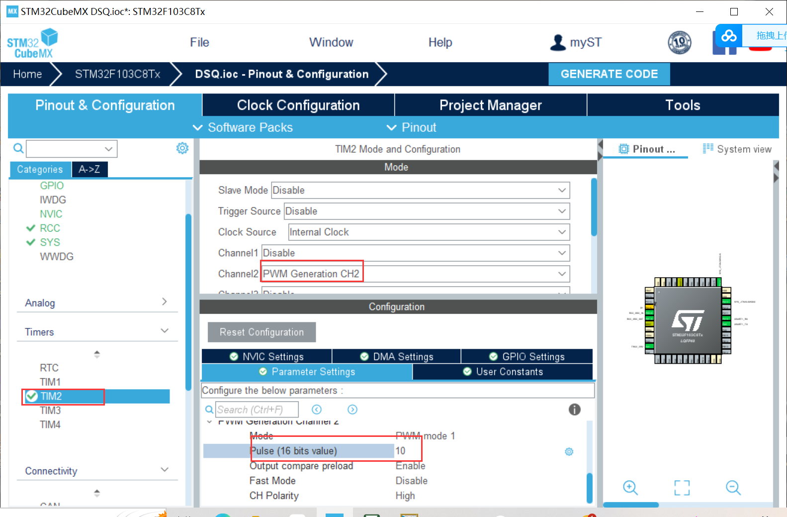
(一)接上更改一点STM32CubeMX相关配置
不用配置TIM3,配置TIM2如下
(二)、keil写入代码
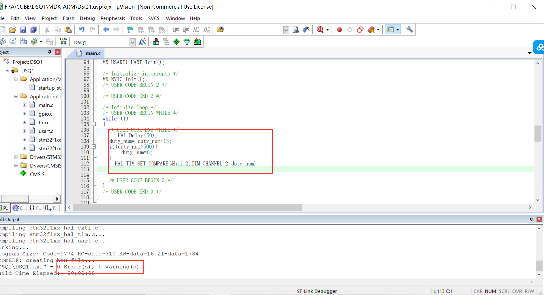
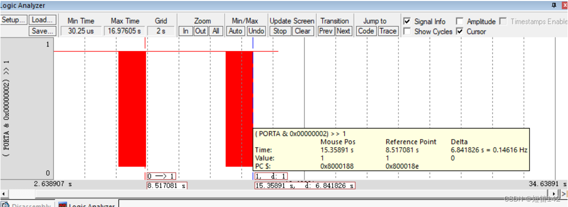
(三)仿真烧录

三、再接上,采用定时器的另外一个通道,编程采集上面的pwm输出信号,获得其周期和脉宽,并重定向输出到串口显示。
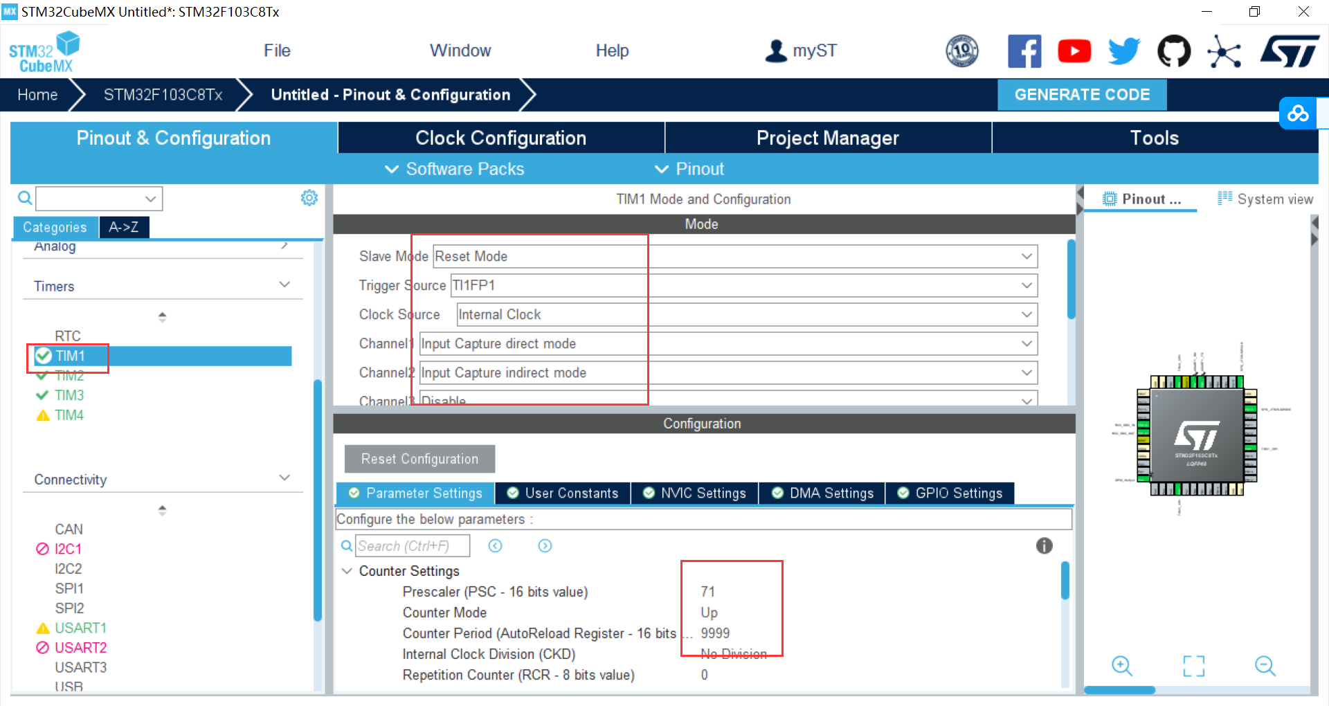
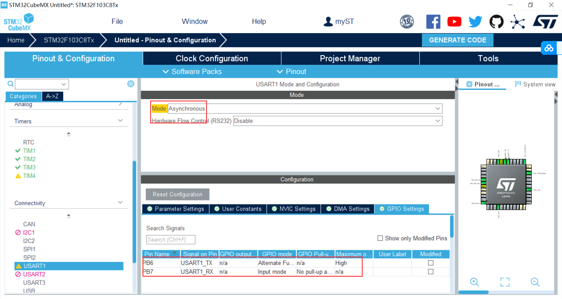
(一)、STM32CubeMX配置
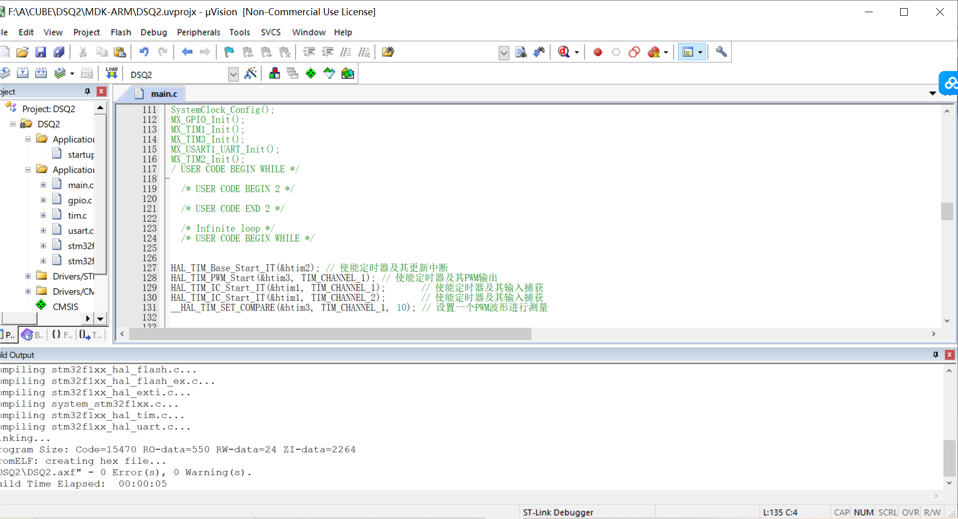
(二)、keil写入代码
/* USER CODE BEGIN Header */
/**
  ******************************************************************************
  * @file           : main.c
  * @brief          : Main program body
  ******************************************************************************
  * @attention
  *
  * Copyright (c) 2023 STMicroelectronics.
  * All rights reserved.
  *
  * This software is licensed under terms that can be found in the LICENSE file
  * in the root directory of this software component.
  * If no LICENSE file comes with this software, it is provided AS-IS.
  *
  ******************************************************************************
  */
/* USER CODE END Header */
/* Includes ------------------------------------------------------------------*/
#include "main.h"
#include "tim.h"
#include "usart.h"
#include "gpio.h"
#include<stdio.h>

/* Private includes ----------------------------------------------------------*/
/* USER CODE BEGIN Includes */

/* USER CODE END Includes */

/* Private typedef -----------------------------------------------------------*/
/* USER CODE BEGIN PTD */

/* USER CODE END PTD */

/* Private define ------------------------------------------------------------*/
/* USER CODE BEGIN PD */

/* USER CODE END PD */

/* Private macro -------------------------------------------------------------*/
/* USER CODE BEGIN PM */

/* USER CODE END PM */

/* Private variables ---------------------------------------------------------*/

/* USER CODE BEGIN PV */

/* USER CODE END PV */

/* Private function prototypes -----------------------------------------------*/
void SystemClock_Config(void);
static void MX_NVIC_Init(void);uint8_t i = 0;

float Duty = 0;
float Frequency = 0;
uint16_t Cap_val1 = 0;
uint16_t Cap_val2 = 0;
/* USER CODE BEGIN PFP */

/* USER CODE END PFP */

/* Private user code ---------------------------------------------------------*/
/* USER CODE BEGIN 0 */

/* USER CODE END 0 */

/**
  * @brief  The application entry point.
  * @retval int
  */
int main(void)
{
  /* USER CODE BEGIN 1 */

  /* USER CODE END 1 */

  /* MCU Configuration--------------------------------------------------------*/

  /* Reset of all peripherals, Initializes the Flash interface and the Systick. */
  HAL_Init();

  /* USER CODE BEGIN Init */

  /* USER CODE END Init */

  /* Configure the system clock */
  SystemClock_Config();

  /* USER CODE BEGIN SysInit */

  /* USER CODE END SysInit */

  /* Initialize all configured peripherals */
  MX_GPIO_Init();
  MX_TIM1_Init();
  MX_TIM2_Init();
  MX_TIM3_Init();
  MX_TIM4_Init();
  MX_USART1_UART_Init();
  /* Initialize interrupts /
MX_NVIC_Init();
/ USER CODE BEGIN 2 */

/* USER CODE END 2 */

/* Infinite loop /
/ USER CODE BEGIN WHILE /
HAL_Init();
SystemClock_Config();
MX_GPIO_Init();
MX_TIM1_Init();
MX_TIM3_Init();
MX_USART1_UART_Init();
MX_TIM2_Init();
/ USER CODE BEGIN WHILE */

  /* USER CODE BEGIN 2 */

  /* USER CODE END 2 */

  /* Infinite loop */
  /* USER CODE BEGIN WHILE */


HAL_TIM_Base_Start_IT(&htim2); // 使能定时器及其更新中断
HAL_TIM_PWM_Start(&htim3, TIM_CHANNEL_1); // 使能定时器及其PWM输出
HAL_TIM_IC_Start_IT(&htim1, TIM_CHANNEL_1);       // 使能定时器及其输入捕获
HAL_TIM_IC_Start_IT(&htim1, TIM_CHANNEL_2);       // 使能定时器及其输入捕获
__HAL_TIM_SET_COMPARE(&htim3, TIM_CHANNEL_1, 10); // 设置一个PWM波形进行测量


  while (1)
  {
    /* USER CODE END WHILE */
 printf("Cap_val1 is :%d ,  Cap_val2 is : %d \r\n", Cap_val1, Cap_val2);
    printf("Duty is :%0.2f%% Frequency is : %0.2f ms\r\n", Duty, Frequency);
    HAL_Delay(1000);


    /* USER CODE BEGIN 3 */
  }
  /* USER CODE END 3 */
}

/**
  * @brief System Clock Configuration
  * @retval None
  */
void HAL_TIM_PeriodElapsedCallback(TIM_HandleTypeDef *tim)
{
if (tim == &htim2)
{
HAL_GPIO_TogglePin(GPIOC, GPIO_PIN_13);
}
}

// 定时输入捕获回调函数 计算占空比和频率
void HAL_TIM_IC_CaptureCallback(TIM_HandleTypeDef *htim)
{
if (htim->Instance == TIM1)
{
if (htim->Channel == HAL_TIM_ACTIVE_CHANNEL_1)
{
Cap_val1 = HAL_TIM_ReadCapturedValue(htim, TIM_CHANNEL_1);
}
if (htim->Channel == HAL_TIM_ACTIVE_CHANNEL_2)
{
Cap_val2 = HAL_TIM_ReadCapturedValue(htim, TIM_CHANNEL_2);
Duty = 100 - (float)Cap_val2 / (float)Cap_val1 * 100;
Frequency = 0.001 * Cap_val1;
}
}
}

void SystemClock_Config(void)
{
  RCC_OscInitTypeDef RCC_OscInitStruct = {0};
  RCC_ClkInitTypeDef RCC_ClkInitStruct = {0};

  /** Initializes the RCC Oscillators according to the specified parameters
  * in the RCC_OscInitTypeDef structure.
  */
  RCC_OscInitStruct.OscillatorType = RCC_OSCILLATORTYPE_HSE;
  RCC_OscInitStruct.HSEState = RCC_HSE_ON;
  RCC_OscInitStruct.HSEPredivValue = RCC_HSE_PREDIV_DIV1;
  RCC_OscInitStruct.HSIState = RCC_HSI_ON;
  RCC_OscInitStruct.PLL.PLLState = RCC_PLL_ON;
  RCC_OscInitStruct.PLL.PLLSource = RCC_PLLSOURCE_HSE;
  RCC_OscInitStruct.PLL.PLLMUL = RCC_PLL_MUL9;
  if (HAL_RCC_OscConfig(&RCC_OscInitStruct) != HAL_OK)
  {
    Error_Handler();
  }

  /** Initializes the CPU, AHB and APB buses clocks
  */
  RCC_ClkInitStruct.ClockType = RCC_CLOCKTYPE_HCLK|RCC_CLOCKTYPE_SYSCLK
                              |RCC_CLOCKTYPE_PCLK1|RCC_CLOCKTYPE_PCLK2;
  RCC_ClkInitStruct.SYSCLKSource = RCC_SYSCLKSOURCE_PLLCLK;
  RCC_ClkInitStruct.AHBCLKDivider = RCC_SYSCLK_DIV1;
  RCC_ClkInitStruct.APB1CLKDivider = RCC_HCLK_DIV2;
  RCC_ClkInitStruct.APB2CLKDivider = RCC_HCLK_DIV1;

  if (HAL_RCC_ClockConfig(&RCC_ClkInitStruct, FLASH_LATENCY_2) != HAL_OK)
  {
    Error_Handler();
  }
}
static void MX_NVIC_Init(void)
{

HAL_NVIC_SetPriority(TIM2_IRQn, 0, 0);
HAL_NVIC_EnableIRQ(TIM2_IRQn);
}


/* USER CODE BEGIN 4 */

/* USER CODE END 4 */

/**
  * @brief  This function is executed in case of error occurrence.
  * @retval None
  */
void Error_Handler(void)
{
  /* USER CODE BEGIN Error_Handler_Debug */
  /* User can add his own implementation to report the HAL error return state */
  __disable_irq();
  while (1)
  {
  }
  /* USER CODE END Error_Handler_Debug */
}

#ifdef  USE_FULL_ASSERT
/**
  * @brief  Reports the name of the source file and the source line number
  *         where the assert_param error has occurred.
  * @param  file: pointer to the source file name
  * @param  line: assert_param error line source number
  * @retval None
  */
void assert_failed(uint8_t *file, uint32_t line)
{
  /* USER CODE BEGIN 6 */
  /* User can add his own implementation to report the file name and line number,
     ex: printf("Wrong parameters value: file %s on line %d\r\n", file, line) */
  /* USER CODE END 6 */
}
#endif /* USE_FULL_ASSERT */
(三)、烧录

四、超声波测距模块
1.HC-SR04测距原理
外部 MCU 给模块 Trig 脚一个大于 10uS 的高电平脉冲;模块会给出一个与距离等比的高电平脉冲信号,可根据脉宽时间“T”算出:
距离=T*C/2 (C 为声速)
声速温度公式:c=(331.45+0.61t/℃)m•s-1 (其中 330.45 是在 0℃)
0℃声速: 330.45M/S
20℃声速: 342.62M/S
40℃声速: 354.85M/S
2.使用STM32实现测距方案
通过本次定时器的学习,
在实现HC-SR04的超声波模块测距我们可以用到定时器的PWM输出功能和输入捕获功能:
一方面,trig信号通过调节PWM波的占空比来输出;
另一方面,输入捕获模块返回的回响信号,记录高电平时间;随后计算,向串口打印输出。
主函数代码编写:
	  __HAL_TIM_SetCompare(&htim3,TIM_CHANNEL_2,10);//10us trig信号输入
	  case 0:
		capture_Cnt++;
	      TIM_RESET_CAPTUREPOLARITY(&htim2,TIM_CHANNEL_1);
		__HAL_TIM_SET_CAPTUREPOLARITY(&htim2, TIM_CHANNEL_1, TIM_ICPOLARITY_RISING);
		HAL_TIM_IC_Start_IT(&htim2, TIM_CHANNEL_1);	//启动输入捕获
		break;
	case 3:
		high_time = capture_Buf[1]- capture_Buf[0];    //高电平时间
	    printf ( "高电平时间 :%d us\n",high_time);
		capture_Cnt = 0;  //清空标志位
	    HAL_Delay(10);
		break;
参考:
[定时器&PWM应用编程-CSDN博客](https://blog.csdn.net/m0_63061253/article/details/134212605)

[嵌入式系统第8-9周作业定时器&PWM应用编程-CSDN博客](https://blog.csdn.net/weixin_65393144/article/details/134223815)


 2844
2844


 被折叠的 条评论
为什么被折叠?
被折叠的 条评论
为什么被折叠?
 到【灌水乐园】发言


