


1. c++基本知识
-
宏定义
typedef int led_t;
typedef int cnt32_t;//计数器 -
using namespace std;
itoa (int, char*, int);//函数# include <stdio.h> # include <stdlib.h> void main (void) { int num = 100; char str[25]; itoa(num, str, 10); printf("The number 'num' is %d and the string 'str' is %s. \n" , num, str); }第一个参数是要转换的数字,第二个参数是要写入转换结果的目标字符串,第三个参数是转移数字时 所用的基数。在上例中,转换基数为10。10:十进制;2:二进制…
-
指针
-
数据在内存中存储时是分块存储的。变量都是存储东西的
-
指针变量是存储了一个指针,int *p;同变量定义相同,定义了一个p变量,但他属于指针型,但他存储的是地址。
-
变量的指针和指针变量:前者是指变量的存储地址,指针理解为地址;后者是是一个变量,这个变量存储的是一个地址。
-
指针变量的定义
int *p;使用
p = &a;//p是一个指针变量,指针变量是存储地址的一块空间,这块空间是存储变量a的地址 -
“&”和“*”的结合方向

-
-
指针数组和数组指针
指针数组:”指针的数组”,首先这个变量是一个数组。一个数组,每个元素都是单独的指针【地址】int *arr[4] = {1,2,3,4}; //arr是指针数组,它有四个元素,每个元素是一个int *类型的指针,这些指针存放着其对应字符串的首地址。数组指针:一个指针,其指向一个数组的地址。
int (*p)[6]; //一个数组指针,总共六个 -
const 作用和简答用法
作用:
1. 对变量声明只读特性,保护变量值以防被修改。
2. 节省空间,避免不必要的内存分配。
用法:int a=2;//普通定义 const int a = 2;//在后续程序中无法修改 //在普通变量中加上const即可 -
static作用:只在本文件中使用变量。
-
extern作用:可以在文件之外使用。
-
结构体的定义和使用:
定义
1. 第一种struct stu{ int a; int b; int c; } //声明结构体变量 struct stu aa,bb; //变量赋初值 aa.a=1; aa.b=2; aa.c=3;- 第二种 将struct stu替换,需要使用关键词typedef
typedef struct stu{
	int a;
	int b;
	int c;
}STU;
STU aa,bb;
//赋初值 同上面一样。
//
//这种方式需要注意
STU aa={
	.a = 1,
	.b = 2,
	.c = 3
	};
定义成这种就能实现关键词替换成自己的类型名“STU”。
结构体数组,数组的数据类型就是定义的结构体。
比如:STU AA[3]={ {1,2,3},//赋值时小的数据类型要对应 {2,3,4}, {3,4,5} };结构体指针
-
struct 结构体名 *指针;
-
结构体访问变量的方法
//定义结构体
struct student{
char name;
int num;
int score;
}*p;
//这里定义了一个结构体指针
//访问方法
//第一种
p->name=
p->num
//第二种
(*p).name
(*p).num
(*p).score
//VGA显示接口的参数定义方法。封装方式值得学习
typedef struct {
	char label[64]; /* Label describing the resolution */
	u32 width; /*Width of the active video frame*/
	u32 height; /*Height of the active video frame*/
	u32 hps; /*Start time of Horizontal sync pulse, in pixel clocks (active width + H. front porch)*/
	u32 hpe; /*End time of Horizontal sync pulse, in pixel clocks (active width + H. front porch + H. sync width)*/
	u32 hmax; /*Total number of pixel clocks per line (active width + H. front porch + H. sync width + H. back porch) */
	u32 hpol; /*hsync pulse polarity*/
	u32 vps; /*Start time of Vertical sync pulse, in lines (active height + V. front porch)*/
	u32 vpe; /*End time of Vertical sync pulse, in lines (active height + V. front porch + V. sync width)*/
	u32 vmax; /*Total number of lines per frame (active height + V. front porch + V. sync width + V. back porch) */
	u32 vpol; /*vsync pulse polarity*/
	double freq; /*Pixel Clock frequency*/
} VideoMode;
//这里运用了static const 结构体的声明
static const VideoMode VMODE_640x480 = {
	.label = "640x480@60Hz",
	.width = 640,
	.height = 480,
	.hps = 656,
	.hpe = 752,
	.hmax = 799,
	.hpol = 0,
	.vps = 490,
	.vpe = 492,
	.vmax = 524,
	.vpol = 0,
	.freq = 25.0
};
- attribute ((aligned(4)))用法
-
字节对齐n 表示几字节。该声明将强制编译器确保(尽它所能)变量分配空间时采用n字节对齐方式。
struct S {

short b[3];

} __attribute__ ((aligned (8)));

typedef int int32_t __attribute__ ((aligned (8)));
int main()
{
 int __attribute__((aligned(8))) a = 1;
 int __attribute__((aligned(4))) b = 2;

 printf("%d %d\n",a,b);

  return 0;
}
-
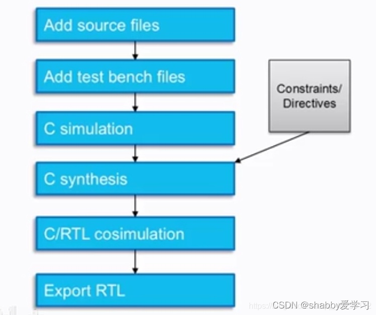
2.1 HLS 设计流水灯实验【包括包括工程的创建,仿真,综合,封装,以及在硬件平台上的实现】
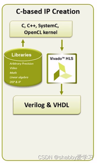
HLS就是用c或者c++完成verilog代码的转换。流程框图是这样的

-
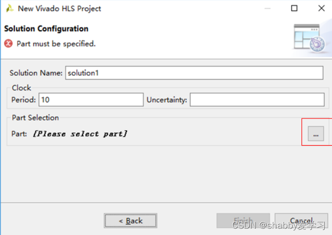
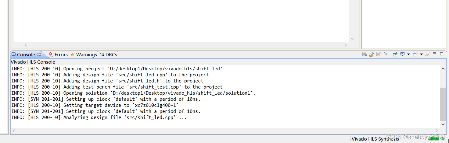
打开 Vivado HLS 开发工具,单击 Creat New Project 创建一个新工程,设置好工程路径和工程名,一直点击Next

-
选择芯片型号,zynq7010,点击next
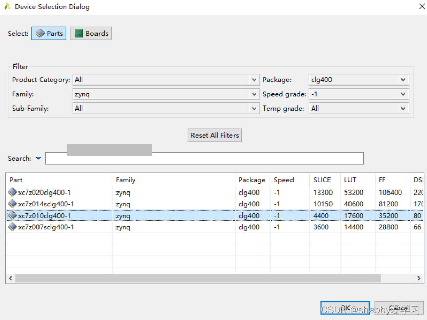
-
右单击 Source,选择 New file,添加一个设计源文件。
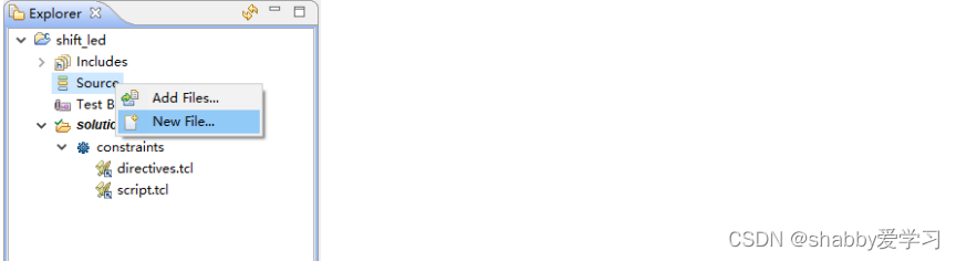
-
功能文件shift_led.cpp 一定要带上后缀
#include "shift_led.h" void shift_led(led_t *led_o,led_t led_i) { led_t tmp_led; cnt32_t i;//for循环的延时变量 tmp_led = led_i; for(i = 0;i < MAX_CNT;i++) { if(i==SHIFT_FLAG) { tmp_led = ((tmp_led>>3)&0x1) + ((tmp_led<<1)&0xE);//左移 *led_o = tmp_led; } } } -
添加一个 shift_led.h 文件
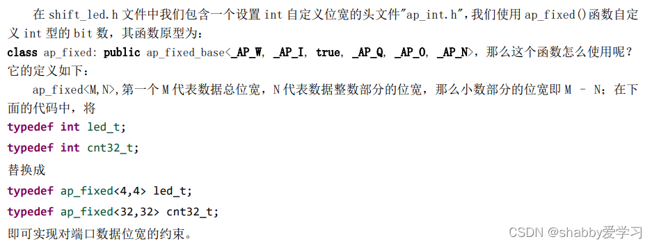
#ifndef _SHIFT_LED_H_ #define _SHIFT_LED_H_ //加入设置int自定义位宽的头文件 #include "ap_int.h" //设置灯半秒动一次,开发板时钟频率是100M //#define MAX_CNT 1000/2 //仅用于仿真,不然时间较长 #define MAX_CNT 100000000/2 #define SHIFT_FLAG MAX_CNT-2 typedef int led_t; typedef int cnt32_t;//计数器 //typedef ap_fixed<4,4> led_t; //第一个4代表总位宽,第二个4代表整数部分的位宽是4,则小数部分位宽=4-4=0 //typedef ap_fixed<32,32> cnt32_t; void shift_led(led_t *led_o,led_t led_i); #endif -
单击 Test Bench,添加一个名为 Test_shift_led.cpp 的测试文件,并添加如下程序
#include "shift_led.h"
#include <stdio.h>
using namespace std;
int main()
{
led_t led_o;
led_t led_i = 0xE;// 1110
const int SHIFT_TIME = 4;
int i;
for(i = 0;i < SHIFT_TIME;i++)
{
	shift_led(&led_o,led_i);
	led_i = led_o;
	char string[25];
	itoa((unsigned int)led_o&0xF,string,2);;//&oxF是为了取led_o的4位,转化为二进制数出
	if(i == 2)
		fprintf(stdout,"shift_out= 0%s\n",string);//数据对齐,高位补零
	else
		fprintf(stdout,"shift_out= %s\n",string);
}
}
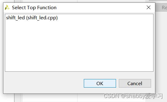
2.2代码综合
- :点击 Project -> Project Settings在 Synthesis 界面下选择综合的顶层函数名
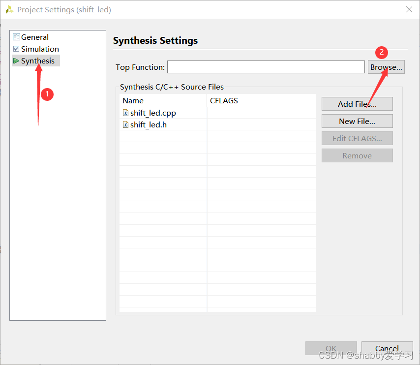
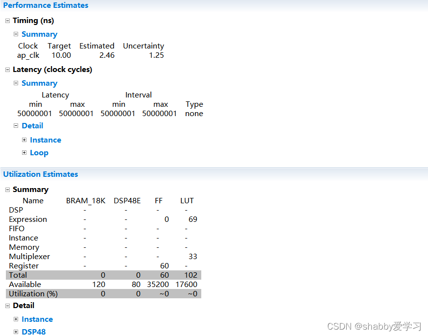
- 因为当前工程中只存在一个 Solution(解决方案),我们选择 Solution –> Run C Synthesis–>Active Solutions 或者直接点击 进行综合,等待一段时间,在未经优化的情况下综合报告如图所示,我们可以看到 FF 和 LUT 使用情况
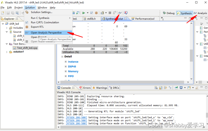
- 单击方框选中的地方点击选择打开分析报告
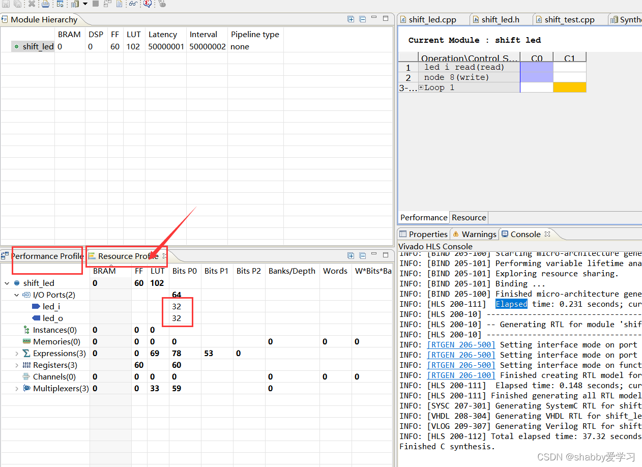
- 在下图所示 1 的地方点击出现 2 所示的 shift_led,点击展开后可以看到 LED 输入和输出位宽均为 32 位,板载是 4 个 LED,那么该怎么去进行优化得到我们想要的结果呢?
2.3代码优化
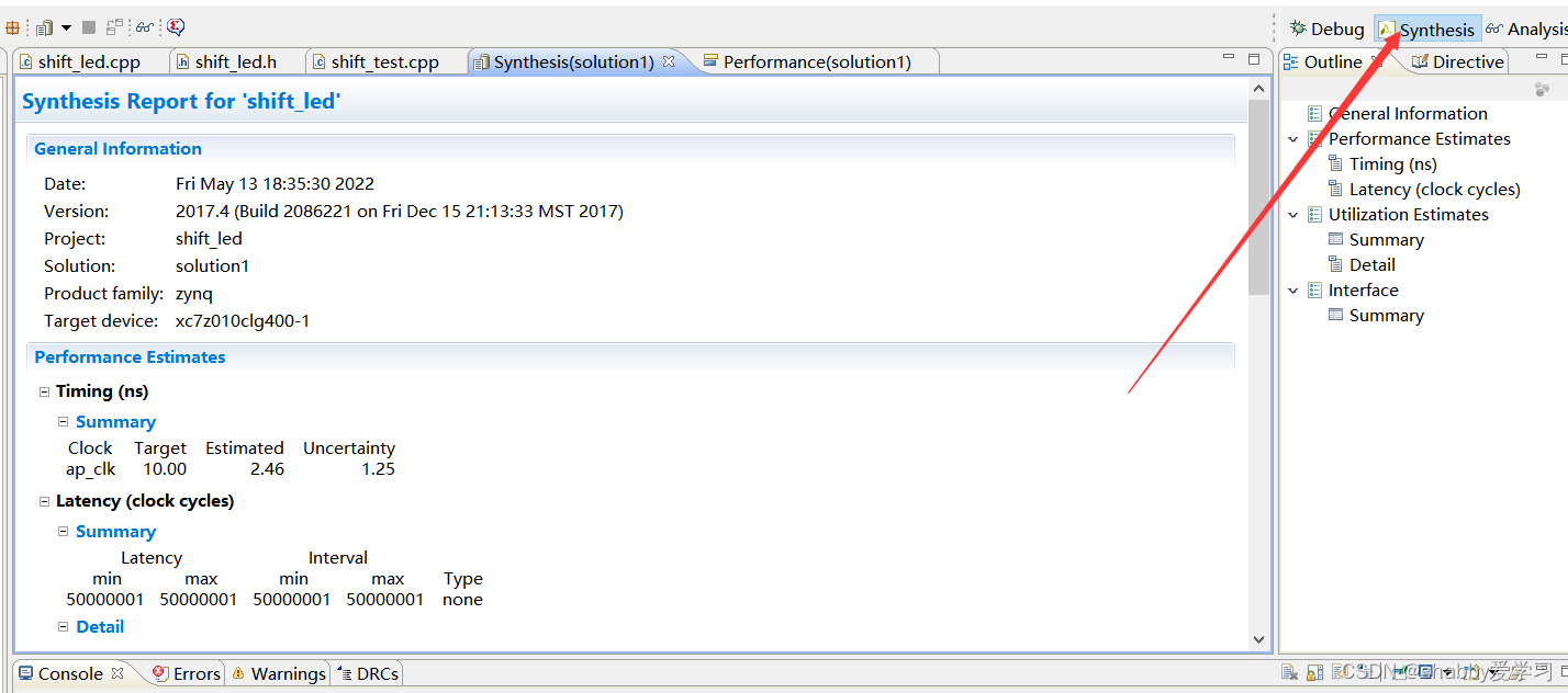
- 点击 Synthesis 切换到工作空间主界面
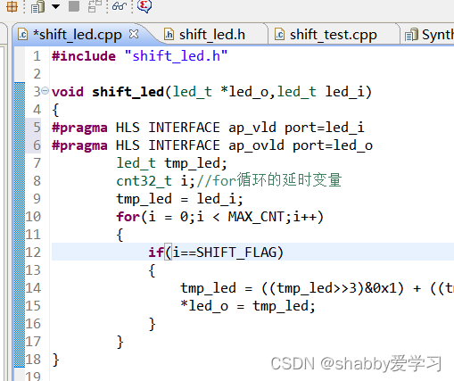
另外再进行端口约束。约束方法如下,双击打开 shift_led.cpp,在需综合的 shift_led.cpp 文件中的 Directive目录下的 led_o 上右键选择 Insert Directive。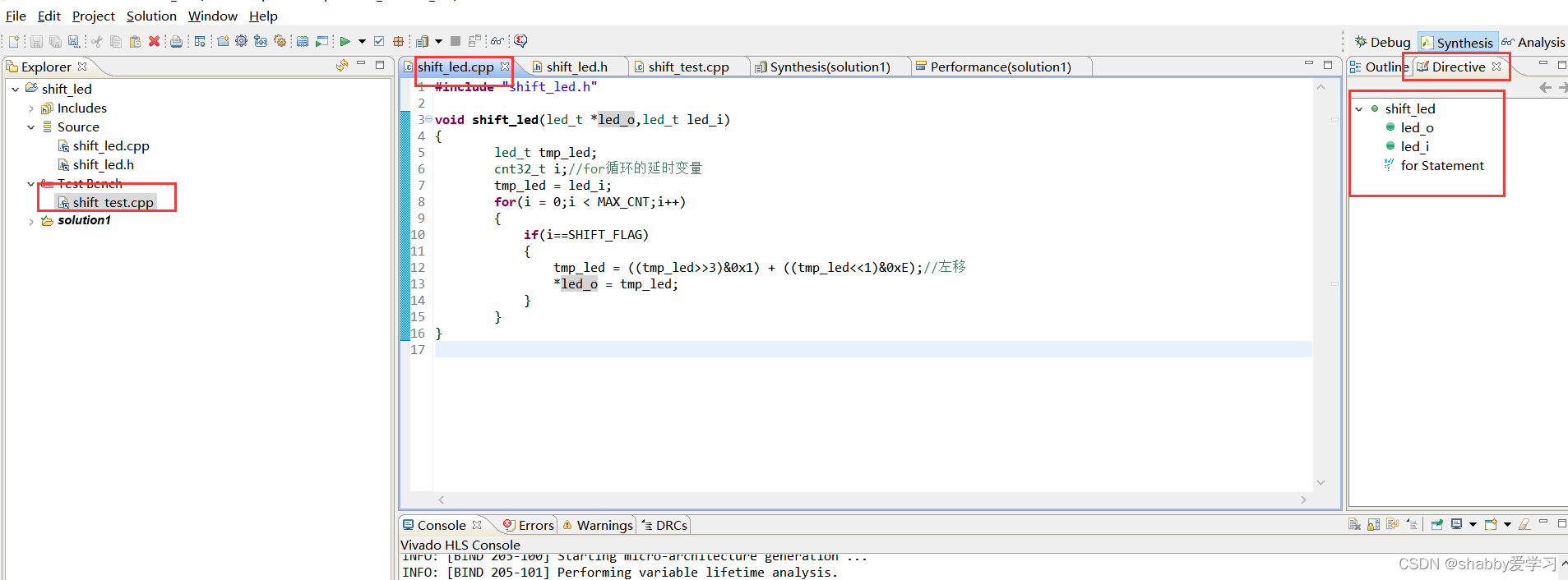
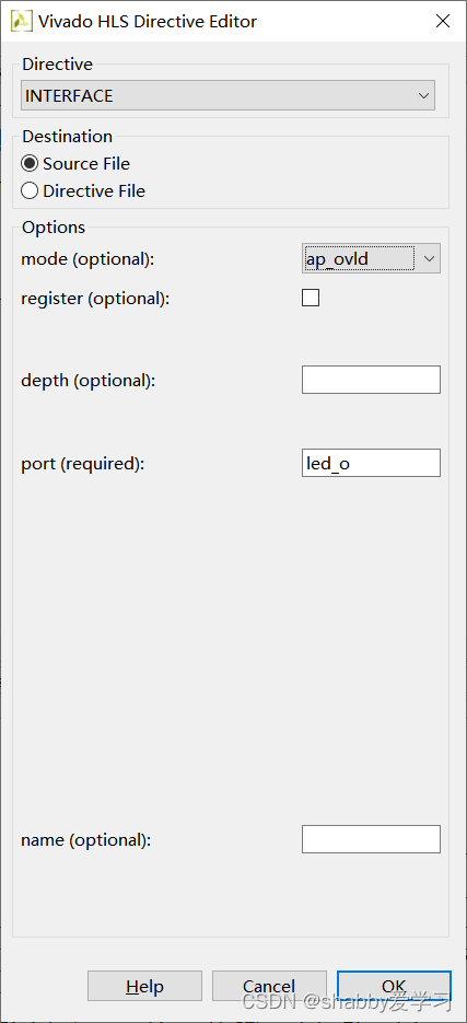
因为 led_o 是接口,所以 Directive 选择为 INTERFACE,Destination 选择为 Source File,那么有的会问了,这两个有什么区别吗?区别就是 Source File 是针对所有的 Solution 采用同一个优化手段,而 Directive File 是对当前的 Solution 有效,mode(optional)我们选为 ap_ovld,即输出使能。
完成后重新综合,查看资源明显减少。
2.4程序仿真
仿真分为 C 代码仿真和 C/RTL 联合仿真。其中 C/RTL 联合仿真可以使用 Vivado 自带的仿真软件仿真,也可以使用第三方仿真软件 Modelsim 进行联合仿真。
C语言仿真
-
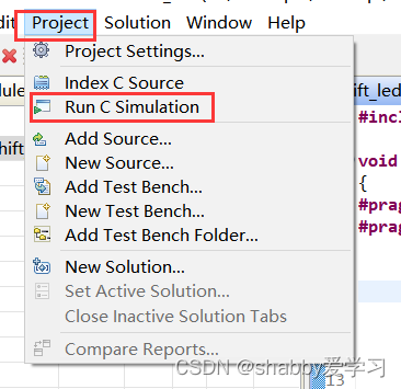
单击 Project 下的 Run C Simulation 或直接单击 开始 C 仿真
-
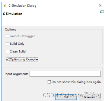
勾选 Optimized Compile,加载编译仿真窗口
-
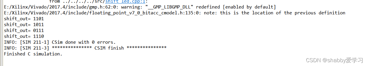
等待一段时间,仿真结果如下,我们可以看到数据循环左移了一位,达到了我们想要的实验效果
-
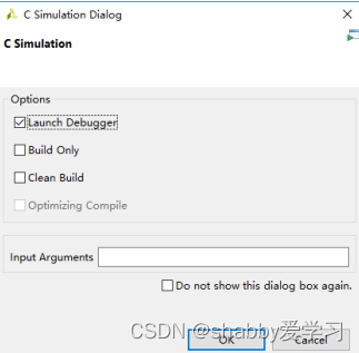
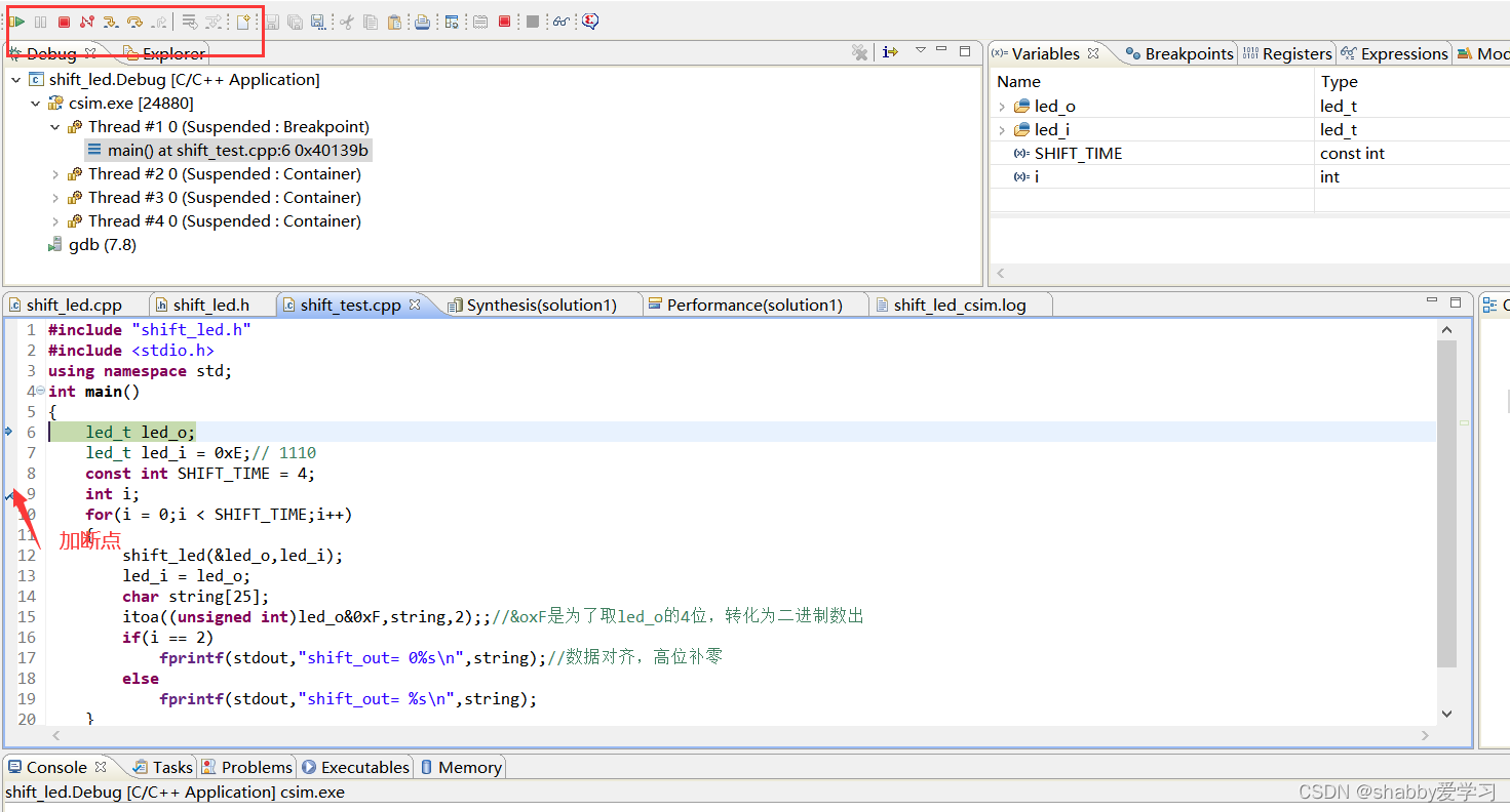
加载调试窗口,出现调试界面,可以添加断点观察调试信号数据
C/RTL 联合仿真
vivado自带仿真工具-
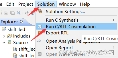
单击 Solution 下的 Run C/RTL cosimulation 运行协同仿真
-
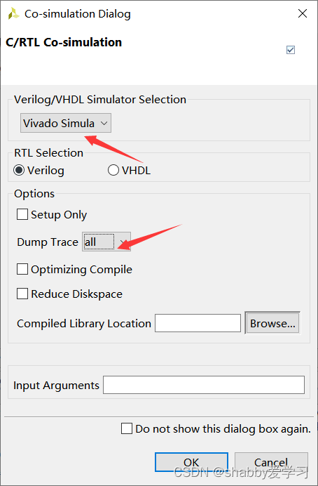
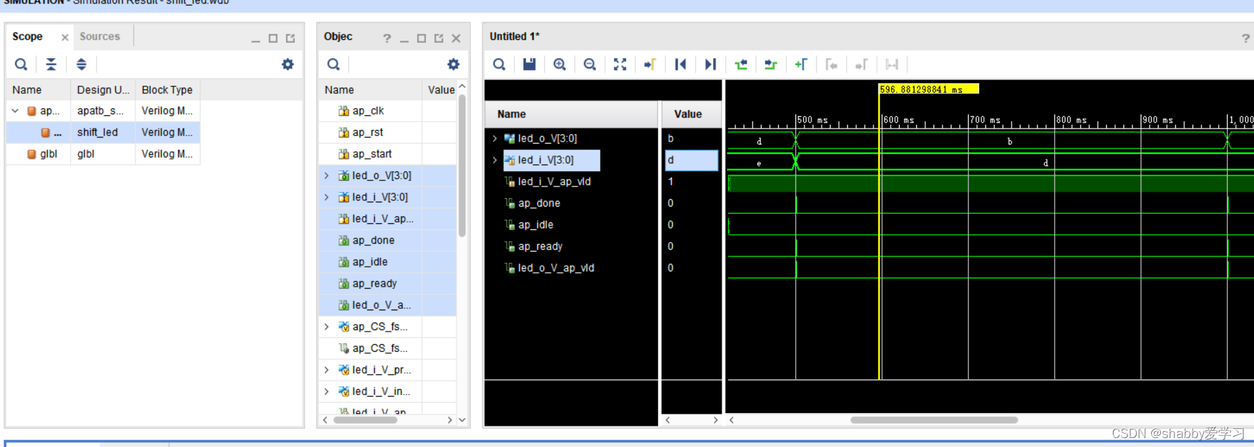
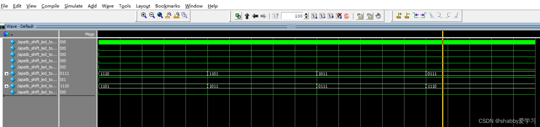
设置如下,点击 OK,开始仿真。Dump Trace 选择 all,可以查看到 RTL 仿真波形
-
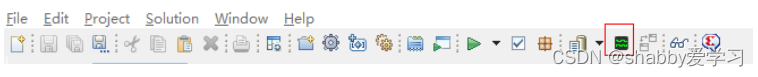
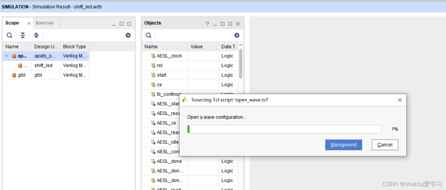
点击图标,打开波形窗口,添加观察信号
这个过程非常花时间需要耐心等待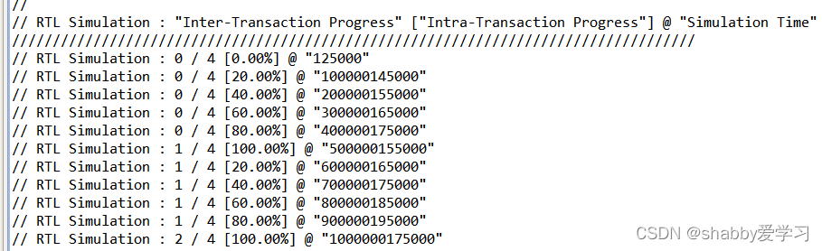
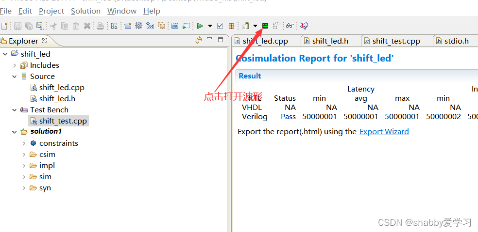
这可是非常卡卡卡卡!
-
-
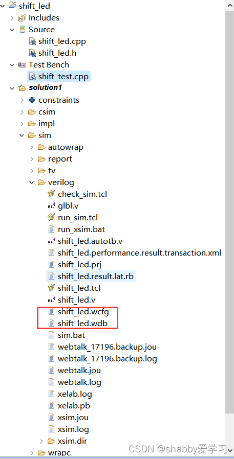
波形文件位置
使用 Modelsim 联合仿真
-
单击 Solution 下的 Run C/RTL cosimulation 运行协同仿真
-
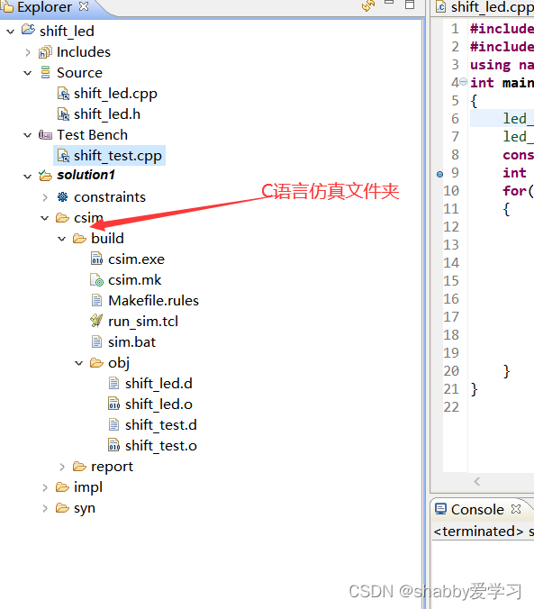
运行协同仿真一段时间后,我们可以发现在 solution1 目录下多了一个 sim 文件夹,在其 verilog 文件夹下可以看到生成的波形文件 shift_led.wlf
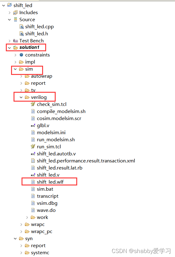
-
通过 modelsim 打开该文件,看关键接口的时序。首先打开 modelsim,然后单击 File 菜单下的 open命令
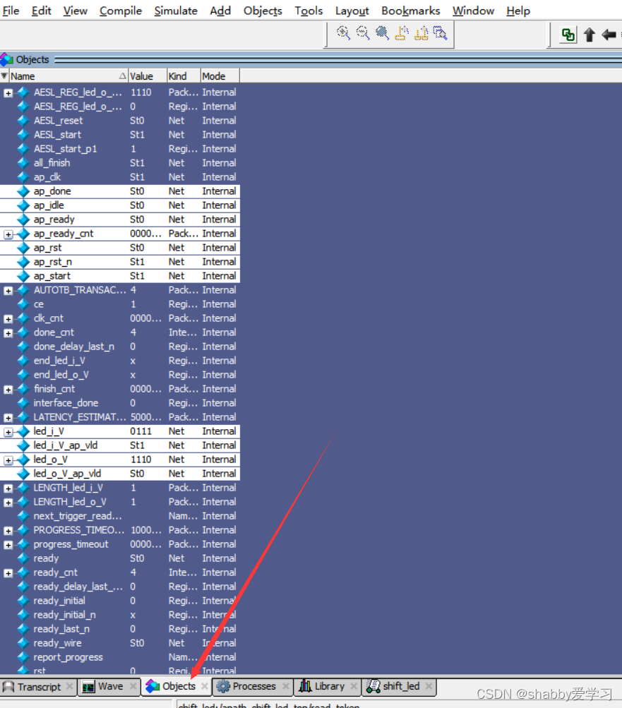
-
在 objects 设置区,按住 ctrl 键选中要查看波形的信号, Add wave
2.5HLS封装
HLS 只是把你的算法实现从 C 到 RTL的转化,而不能在硬件平台上进行测试,需要把 HLS 工程打包成一个 IP 以便于 Vivado 进行调用。
-
单击 Solution 菜单下的 Export RTL 或直接单击 导出 RTL 级
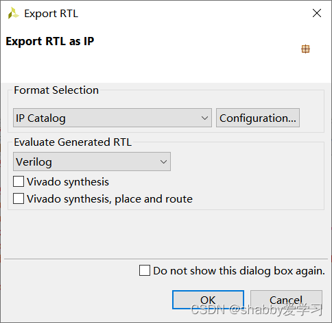
-
点击 configuration 对一些参数进行补充
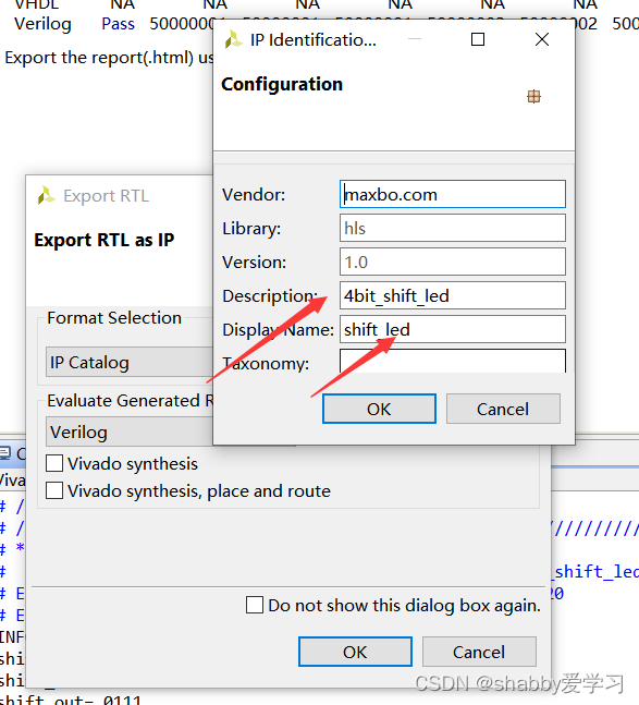
如果出现这种报错,把电脑时钟设置成2019年以前就能通过编译
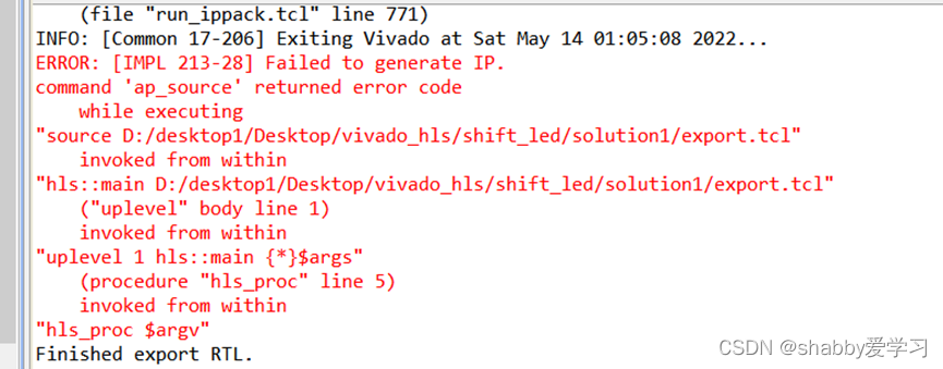
-
等待一段时间后在 solution1 目录下多了一个 impl 文件夹,并且在 ip 文件夹生成了一个压缩包,这就是打包好的 IP,在 Vivado 中进行使用
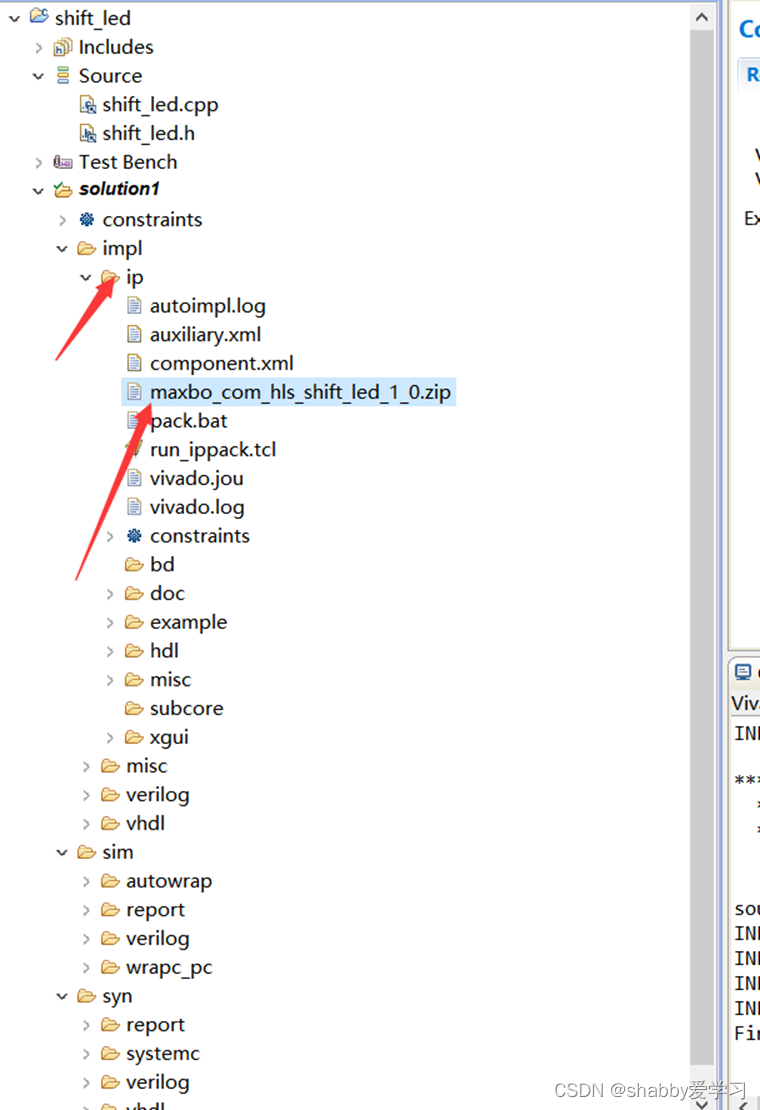
2.6硬件平台
-
按照zynq新建工程
-
完成后,压缩包解压然后,选择 IP->Repository,进入添加 IP 设置区、
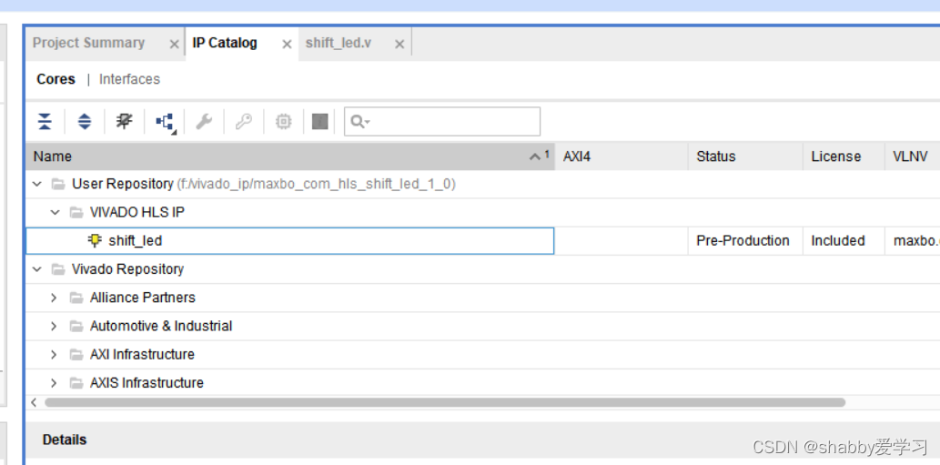
设置IP名字,在顶层中例化IP
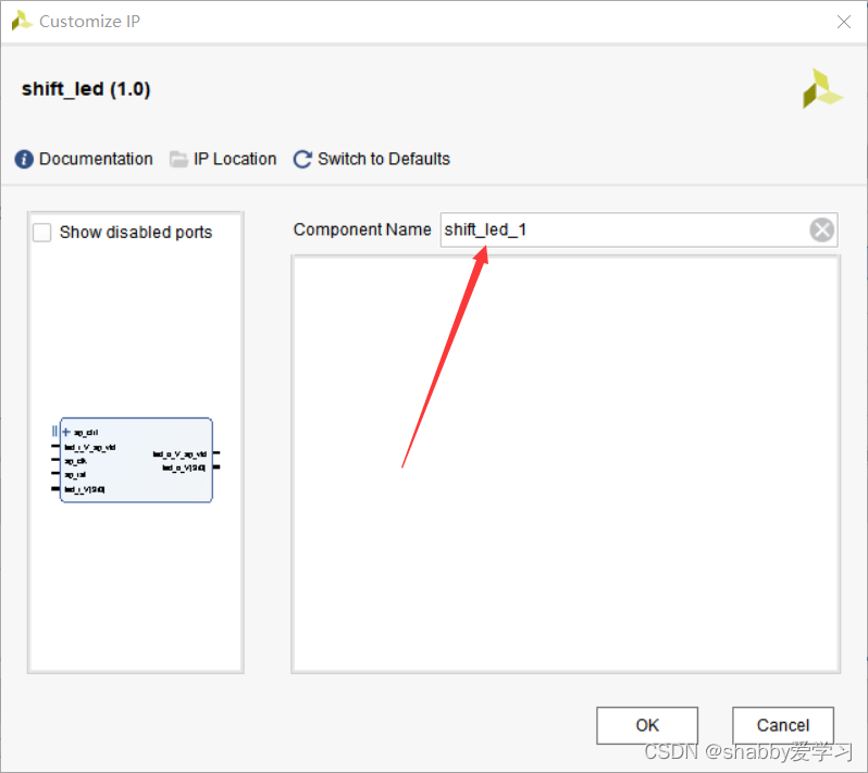
-
创建一个名为 shift_led 的 Verilog 文件
module shift_led
 #(
 parameter DATA_WIDTH = 4//数据位宽
 )
 (
	input i_clk,
	input i_rst_n,
	output reg [DATA_WIDTH-1:0] led
 );
	 reg [1:0] cnt ;
	 reg [DATA_WIDTH-1:0] led_i_V ;
	 wire ap_start ;
	 wire led_i_vld;
	 wire [DATA_WIDTH-1:0] led_o_V ;
	 always@(posedge i_clk or negedge i_rst_n)begin
		 if(i_rst_n == 1'b0)
			 cnt <= 2'd0;
		 else if(cnt[1]==1'b0)
			 cnt <= cnt + 1'b1;
	 end
	 always@(posedge i_clk or negedge i_rst_n)begin
		 if(i_rst_n == 1'b0)
			 led_i_V <= 4'd0;
		 else if(cnt[0]==1'b1)
			 led_i_V <= 4'h1;
		 else if(led_o_vld == 1'b1)
		 led_i_V <= led_o_V;
	 end
	 always@(posedge i_clk or negedge i_rst_n)begin
		 if(i_rst_n == 1'b0)
			 led <= 1'b0;
		 else if(led_o_vld == 1'b1)
			 led <= led_o_V;
	 end
	 assign ap_start = cnt[1];
	 assign led_i_vld = cnt[1];

	 shift_led_0 u_shift_led_0(
		  .led_o_V_ap_vld (led_o_vld),// output wire led_o_vld
		  .led_i_V_ap_vld (led_i_vld),// input wire led_i_vld
		  .ap_clk (i_clk ),// input wire ap_clk
		  .ap_rst (~i_rst_n ),// input wire ap_rst
		  .ap_start (ap_start ),// input wire ap_start
		  .ap_done ( ),// output wire ap_done
		  .ap_idle ( ),// output wire ap_idle
		  .ap_ready ( ),// output wire ap_ready
		  .led_i_V (led_i_V ),// output wire [3 : 0] led_o_V
		  .led_o_V (led_o_V ) // input wire [3 : 0] led_i_V
  );
 endmodule
- 引脚约束,下载调试


 454
454

 被折叠的 条评论
为什么被折叠?
被折叠的 条评论
为什么被折叠?
 到【灌水乐园】发言


