


3D projection
From Wikipedia, the free encyclopedia
A 3D projection is a mathematical transformation used to project three dimensional points onto a two dimensional plane. Often this is done to simulate the relationship of the camera to subject. 3D projection is often the first step in the process of representing three dimensional shapes two dimensionally in computer graphics, a process known as rendering.
The following algorithm was a standard on early computer simulations and videogames, and it is still in use with heavy modifications for each particular case. This article describes the simple, general case.
Contents[hide] |
<script type="text/javascript"> // </script>
[edit] Data necessary for projection
Data about the objects to render is usually stored as a collection of points, linked together in triangles. Each point is a set of three numbers, representing its X,Y,Z coordinates from an origin relative to the object they belong to. Each triangle is a set of three such points. In addition, the object has three coordinates X,Y,Z and some kind of rotation, for example, three angles alpha, beta and gamma, describing its position and orientation relative to a "world" reference frame.
Last comes the observer (or camera). The observer has a set of three X,Y,Z coordinates and three alpha, beta and gamma angles, describing the observer's position and the direction in which it is pointing.
All this data is usually stored using floating point values, although many programs convert them to integers at various points in the algorithm to speed up the calculations.
[edit] First step: world transform
The first step is to transform the point's coordinates, taking into account the position and orientation of the object they belong to. This is done using a set of four matrices: (The matrix used here is column major, i.e., v' = Matrix*v, the same in OpenGL but different in DirectX.)
-
 — object
translation
— object
translation
-
 — rotation about the
x-axis
— rotation about the
x-axis
-
 — rotation about the
y-axis
— rotation about the
y-axis
-
 — rotation about the
z-axis.
— rotation about the
z-axis.
The four matrices are multiplied together, and the result is the world transform matrix: a matrix that, if a point's coordinates were multiplied by it, would result in the point's coordinates being expressed in the "world" reference frame.
Note that unlike multiplication between numbers, the order used to multiply the matrices is significant; changing the order will change the results too. When dealing with the three rotation matrices, a fixed order is good for the necessity of the moment that must be chosen. The object should be rotated before it is translated, since otherwise the position of the object in the world would get rotated around the centre of the world, wherever that happens to be.
World transform = Translation × Rotation
To complete the transform in the most general way possible, another matrix called the scaling matrix is used to scale the model along the axes. This matrix is multiplied to the four given above to yield the complete world transform. The form of this matrix is:
-
 — where
sx,
sy, and
sz are the scaling factors along the three co-ordinate axes.
— where
sx,
sy, and
sz are the scaling factors along the three co-ordinate axes.
Since it is usually convenient to scale the model in its own model space or coordinate system, scaling should be the first transformation applied. The final transform thus becomes:
World transform = Translation × Rotation × Scaling
(as in some computer graphics books or programming APIs such as DirectX, it uses matrices with translation vectors in the bottom row, in this scheme, the order of matrices would be reversed.)
-
 — final result of Translation ×
x ×
y ×
z × Scaling.
— final result of Translation ×
x ×
y ×
z × Scaling.
[edit] Second step: camera transform
The second step is virtually identical to the first one, except for the fact that it uses the six coordinates of the observer instead of the object, and the inverses of the matrices should be used, and they should be multiplied in the opposite order. (Note that (A×B)-1=B-1×A-1.) The resulting matrix can transform coordinates from the world reference frame to the observer's one.
The camera typically looks in its z direction, the x direction is typically left, and the y direction is typically up.
-
 — inverse object translation (the inverse of a translation is a translation in the opposite direction).
-
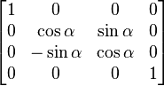 — inverse rotation about the
x-axis (the inverse of a rotation is a rotation in the opposite direction. Note that sin(−x) = −sin(
x), and cos(−
x) = cos(
x)).
— inverse rotation about the
x-axis (the inverse of a rotation is a rotation in the opposite direction. Note that sin(−x) = −sin(
x), and cos(−
x) = cos(
x)).
-
 — inverse rotation about the
y-axis.
— inverse rotation about the
y-axis.
-
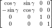 — inverse rotation about the
z-axis.
— inverse rotation about the
z-axis.
The two matrices obtained from the first two steps can be multiplied together to get a matrix capable of transforming a point's coordinates from the object's reference frame to the observer's reference frame.
- Camera transform = inverse rotation × inverse translation
- Transform so far = camera transform × world transform.
[edit] Third step: perspective transform
The resulting coordinates would be good for an isometric projection or something similar, but realistic rendering requires an additional step to simulate perspective distortion. Indeed, this simulated perspective is the main aid for the viewer to judge distances in the simulated view.
A perspective distortion can be generated using the following 4×4 matrix:
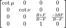
where μ is the angle between a line pointing out of the camera in z direction and the plane through the camera and the right-hand edge of the screen, and ν is the angle between the same line and the plane through the camera and the top edge of the screen. This projection should look correct, if you are looking with one eye; your actual physical eye is located on the line through the centre of the screen normal to the screen, and μ and ν are physically measured assuming your eye is the camera. On typical computer screens as of 2003, cot μ is probably about 11/3 times cot ν, and cot μ might be about 1 to 5, depending on how far from the screen you are.
F is a positive number representing the distance of the observer from the front clipping plane, which is the closest any object can be to the camera. B is a positive number representing the distance to the back clipping plane, the farthest away any object can be. If objects can be at an unlimited distance from the camera, B can be infinite, in which case (B + F)/(B − F) = 1 and −2BF/(B − F) = −2F.
If you are not using a Z-buffer and all objects are in front of the camera, you can just use 0 instead of (B + F)/(B − F) and −2BF/(B − F). (Or anything you want.)
All the calculated matrices can be multiplied together to get a final transformation matrix. One can multiply each of the points (represented as a vector of three coordinates) by this matrix, and directly obtain the screen coordinate at which the point must be drawn. The vector must be extended to four dimensions using homogeneous coordinates:

Note that in computer graphics libraries, such as OpenGL, you should give the matrices in the opposite order than they should be applied, that is, first the perspective transform, then the camera transform, then the object transform, as the graphics library applies the transformations in the opposite order than you give the transformations in. This is useful, since the world transform typically changes more often than the camera transform, and the camera transform changes more often than the perspective transform. One can, for example, pop the world transform off a stack of transforms and multiply a new world transform on, without having to do anything with the camera transform and perspective transform.
Remember that {x'/ω', y'/ω'} are the final coordinates, where {−1, −1} is typically the bottom left corner of the screen, {1, 1} is the top right corner of the screen, {1, −1} is the bottom right corner of the screen and {−1, 1} is the top left corner of the screen.
If using a Z-buffer, a z'/ω' value of −1 corresponds to the front of the Z-buffer, and a value of 1 corresponds to the back of the Z-buffer. If the front clipping plane is too close, a finite precision Z-buffer will be less accurate. The same applies to the back clipping plane, but to a significantly lesser degree; a Z-buffer works correctly with the back clipping plane at an infinite distance, but not with the front clipping plane at 0 distance.
Objects should only be drawn where −1 ≤ z'/ω' ≤ 1. If it is less than −1, the object is in front of the front clipping plane. If it is more than 1, the object is behind the back clipping plane. To draw a simple single-colour triangle, {x'/ω', y'/ω'} for the three corners contains sufficient information. To draw a textured triangle, where one of the corners of the triangle is behind the camera, all the coordinates {x', y', z', ω'} for all three points are needed, otherwise the texture would not have the correct perspective, and a point behind the camera would not appear in the correct location. In fact, the projection of a triangle where a point is behind the camera is not technically a triangle, since the area is infinite and two of the angles sum to more than 180°, the third angle being effectively negative. (Typical modern graphics libraries use all four coordinates, and can correctly draw "triangles" with some points behind the camera.) Also, if a point is on the plane through the camera normal to the camera direction, ω' is 0, and {x'/ω', y'/ω'} is meaningless.
[edit] Simple version

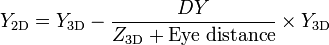
where  is the distance between the eye and the 3D point in the X/Y axis, a large positive Z is towards the horizon and 0 is screen.
[edit] Note about terminology
All of the above-described 4-by-4 transformation matrices containing homogeneous coordinates are often classified, somewhat improperly, as "homogeneous transformation matrices". However, most of them (except for simple rotation and scaling matrices) represent definitely non-homogeneous and non-linear transformations (translations, roto-translations, perspective projections). And even the matrices themselves, as you can see, look rather heterogeneous, i.e. composed of different kinds of elements. Since they are multi-purpose transformation matrices, capable of representing both affine and projective transformations, they might be called "general transformation matrices", or, depending on the application, "affine transformation" or "perspective projection" matrices. Moreover, since the homogeneous coordinates describe a projective vector space, they might be also called "projective space transformation matrices".
[edit] See also
Personal tools
Toolbox
In other languages


- This page was last modified 08:28, 3 March 2007.
- All text is available under the terms of the GNU Free Documentation License. (See Copyrights for details.)
Wikipedia® is a registered trademark of the Wikimedia Foundation, Inc., a US-registered 501(c)(3) tax-deductible nonprofit charity. - Privacy policy
- About Wikipedia
- Disclaimers


 被折叠的 条评论
为什么被折叠?
被折叠的 条评论
为什么被折叠?
 到【灌水乐园】发言


