


目录-----接单片机设计:DPJSJ0X78
一、识别目标
使用OpenMV摄像头模块来识别网球,并将识别到的网球在图像中的坐标通过串口通信传输出去,以便其他设备接收并利用这些坐标信息进行后续处理或操作。
二、可供采取的识别方式
1. 阈值识别:
阈值识别是一种基于颜色、亮度或其他图像特征设定固定阈值来进行物体识别的方法。在OpenMV IDE(集成开发环境)中,可以通过分析网球在图像中的颜色特征,手动设定或自动获取颜色阈值,然后利用这些阈值对图像进行二值化处理,从而识别出网球。
2. 多阈值识别:
多阈值识别是对阈值识别方法的扩展,它使用多个阈值来处理更复杂的颜色或亮度变化。在网球识别中,由于光照条件、网球材质或表面磨损等因素,网球的颜色可能会有所变化。因此,可以设定多个颜色阈值范围,以覆盖网球在不同条件下的颜色变化。然后,对每个阈值范围分别进行阈值识别,并将结果合并以得到更准确的网球区域。
3. 多阈值加最多像素点识别:
在多阈值识别的基础上,增加像素量作为识别条件可以提高识别的准确性。具体做法是,在确定了网球可能的颜色范围后,不仅检查像素颜色是否满足阈值条件,还统计满足条件的像素数量。如果某个连通区域中的像素数量超过预设的阈值(即最小网球像素量),则认为该区域是一个网球。这种方法有助于减少误识别,例如将图像中的噪点或类似颜色的其他物体误认为是网球。
4. 训练神经网络目标检测(重点) :
训练模型识别是一种基于机器学习或深度学习的方法。OpenMV官方提供了训练神经网络目标检测的教程(训练神经网络目标检测),可学习这个教程进行改造,实现自己想要的物品识别。
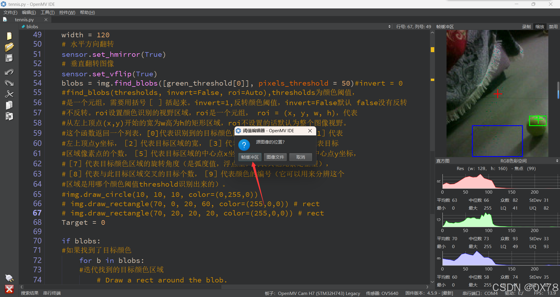
三、单阈值识别
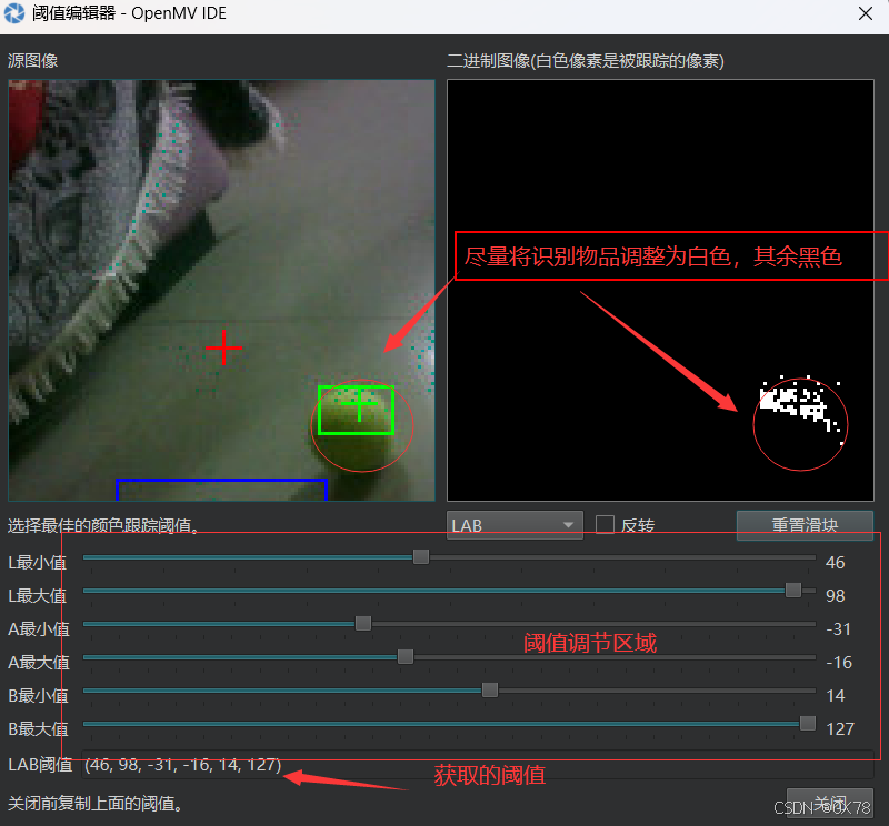
1. 网球阈值获取
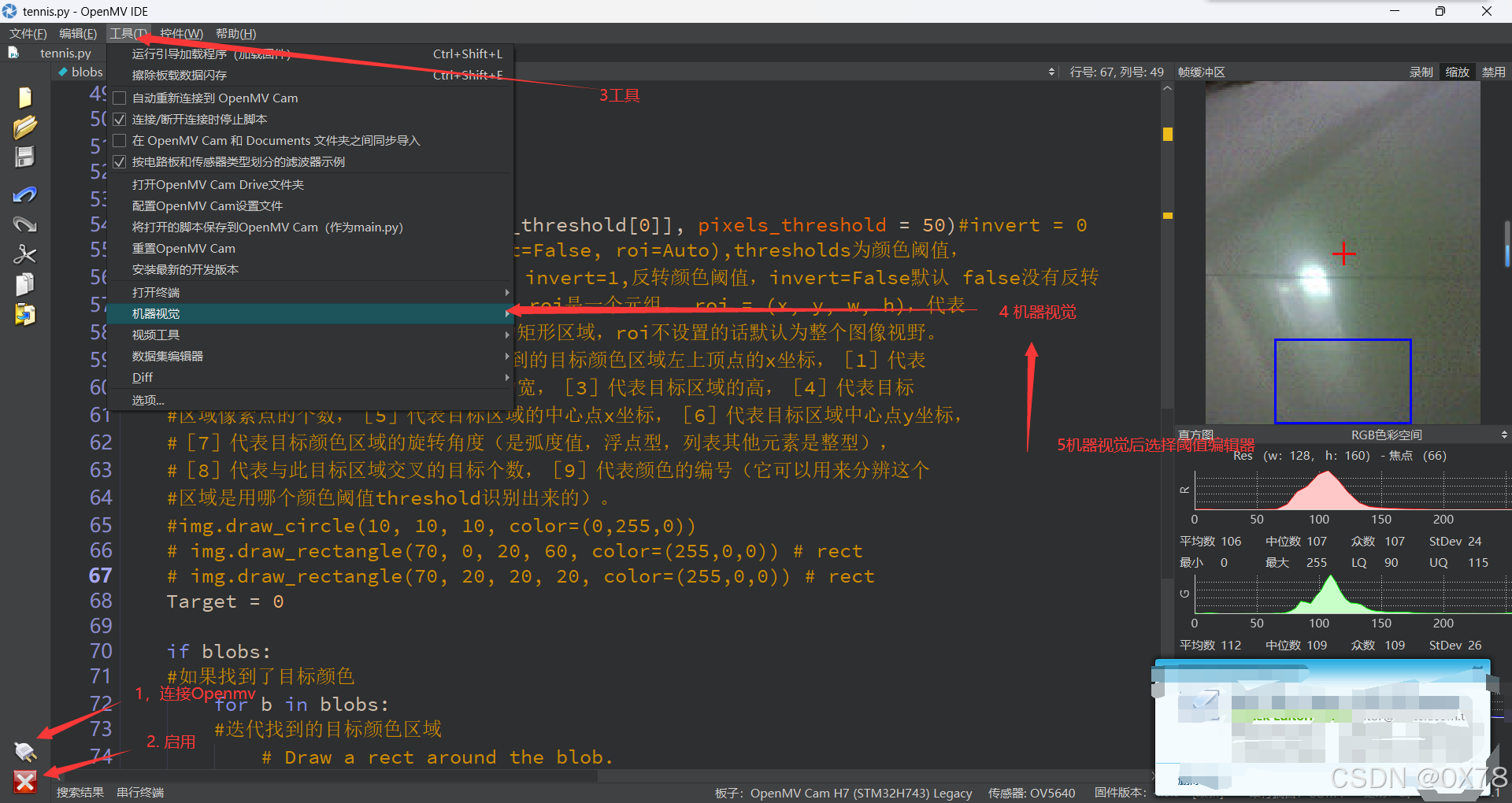
这里要保证摄像头处有网球
2. 代码编写
# 色块监测 例子
#
# 这个例子展示了如何通过find_blobs()函数来查找图像中的色块
# 这个例子查找的颜色是深绿色

import sensor, image, time
import ustruct
# 颜色追踪的例子,一定要控制环境的光,保持光线是稳定的。
green_threshold_num = 2
green_threshold = {}
green_threshold[0] = (48, 100, -128, -8, 20, 127)
green_threshold[1] = (15, 100, -46, -16, 12, 61)
# green_threshold   = (15, 100, -46, -16, 12, 61)
#设置绿色的阈值,括号里面的数值分别是L A B 的最大值和最小值(minL, maxL, minA,
# maxA, minB, maxB),LAB的值在图像左侧三个坐标图中选取。如果是灰度图,则只需
#设置(min, max)两个数字即可。

import display
import time
from pyb import UART

# UART 3, and baudrate.
uart = UART(3, 115200)
uart.init(115200, bits=8, parity=None, stop=1)
#RX P5      TX P4
# 初始化串口


sensor.reset() # 初始化摄像头
sensor.set_pixformat(sensor.RGB565) # 格式为 RGB565.
sensor.set_framesize(sensor.QQVGA2) # 使用 QQVGA 速度快一些
sensor.skip_frames(time = 2000) # 跳过2000s,使新设置生效,并自动调节白平衡
sensor.set_auto_gain(False) # 关闭自动自动增益。默认开启的,在颜色识别中,一定要关闭白平衡。
sensor.set_auto_whitebal(False)
#关闭白平衡。白平衡是默认开启的,在颜色识别中,一定要关闭白平衡。
clock = time.clock() # 追踪帧率

lcd = display.SPIDisplay()


while(True):
    #lcd.write(sensor.snapshot())  # Take a picture and display the image.
    clock.tick() # Track elapsed milliseconds between snapshots().
    img = sensor.snapshot() # 从感光芯片获得一张图像  宽=128 高=160
    lcd.write(img)  # Take a picture and display the image.
    length = 160
    width = 120
    # 水平方向翻转
    sensor.set_hmirror(True)
    # 垂直翻转图像
    sensor.set_vflip(True)
    blobs = img.find_blobs([green_threshold[0]], pixels_threshold = 50)#invert = 0
    #find_blobs(thresholds, invert=False, roi=Auto),thresholds为颜色阈值,
    #是一个元组,需要用括号[ ]括起来。invert=1,反转颜色阈值,invert=False默认 false没有反转
    #不反转。roi设置颜色识别的视野区域,roi是一个元组, roi = (x, y, w, h),代表
    #从左上顶点(x,y)开始的宽为w高为h的矩形区域,roi不设置的话默认为整个图像视野。
    #这个函数返回一个列表,[0]代表识别到的目标颜色区域左上顶点的x坐标,[1]代表
    #左上顶点y坐标,[2]代表目标区域的宽,[3]代表目标区域的高,[4]代表目标
    #区域像素点的个数,[5]代表目标区域的中心点x坐标,[6]代表目标区域中心点y坐标,
    #[7]代表目标颜色区域的旋转角度(是弧度值,浮点型,列表其他元素是整型),
    #[8]代表与此目标区域交叉的目标个数,[9]代表颜色的编号(它可以用来分辨这个
    #区域是用哪个颜色阈值threshold识别出来的)。
    #img.draw_circle(10, 10, 10, color=(0,255,0))
    # img.draw_rectangle(70, 0, 20, 60, color=(255,0,0)) # rect
    # img.draw_rectangle(70, 20, 20, 20, color=(255,0,0)) # rect
    Target = 0

    if blobs:
    #如果找到了目标颜色
        for b in blobs:
        #迭代找到的目标颜色区域
            # Draw a rect around the blob.
            if abs(b[3] - b[2]) <= 10 :
                img.draw_rectangle(b[0:4], color=(0,255,0)) # rect
                #用矩形标记出目标颜色区域
                img.draw_cross(b[5], b[6], color=(0,255,0)) # cx, cy
                #在目标颜色区域的中心画十字形标记
                #print(b[5], b[6])
                img.draw_cross(64, 80, color=(255,0,0)) # cx, cy
                Target = 1
                uart.write("Target:" + str(Target) + ";X:" + str(b[5]) + ";Y:" + str(img.height() - b[6]) + ";TargetX:" + str(img.width()) + ";TargetY:" + str(img.height()) + ";")

                # 如果没有找到目标颜色
    if Target == 0:
        uart.write("Target:" + str(Target) + ";X:" + "0" + ";Y:" + "0" + ";TargetX:" + str(img.width()) + ";TargetY:" + str(img.height()) + ";")

    img.draw_cross(64, 80, color=(255,0,0)) # cx, cy
    img.draw_rectangle(32,120,128-32*2,40, color=(0,0,255))
    lcd.write(img)  # Take a picture and display the image.


    #print(clock.fps()) # 注意: 你的OpenMV连到电脑后帧率大概为原来的一半
    #如果断开电脑,帧率会增加
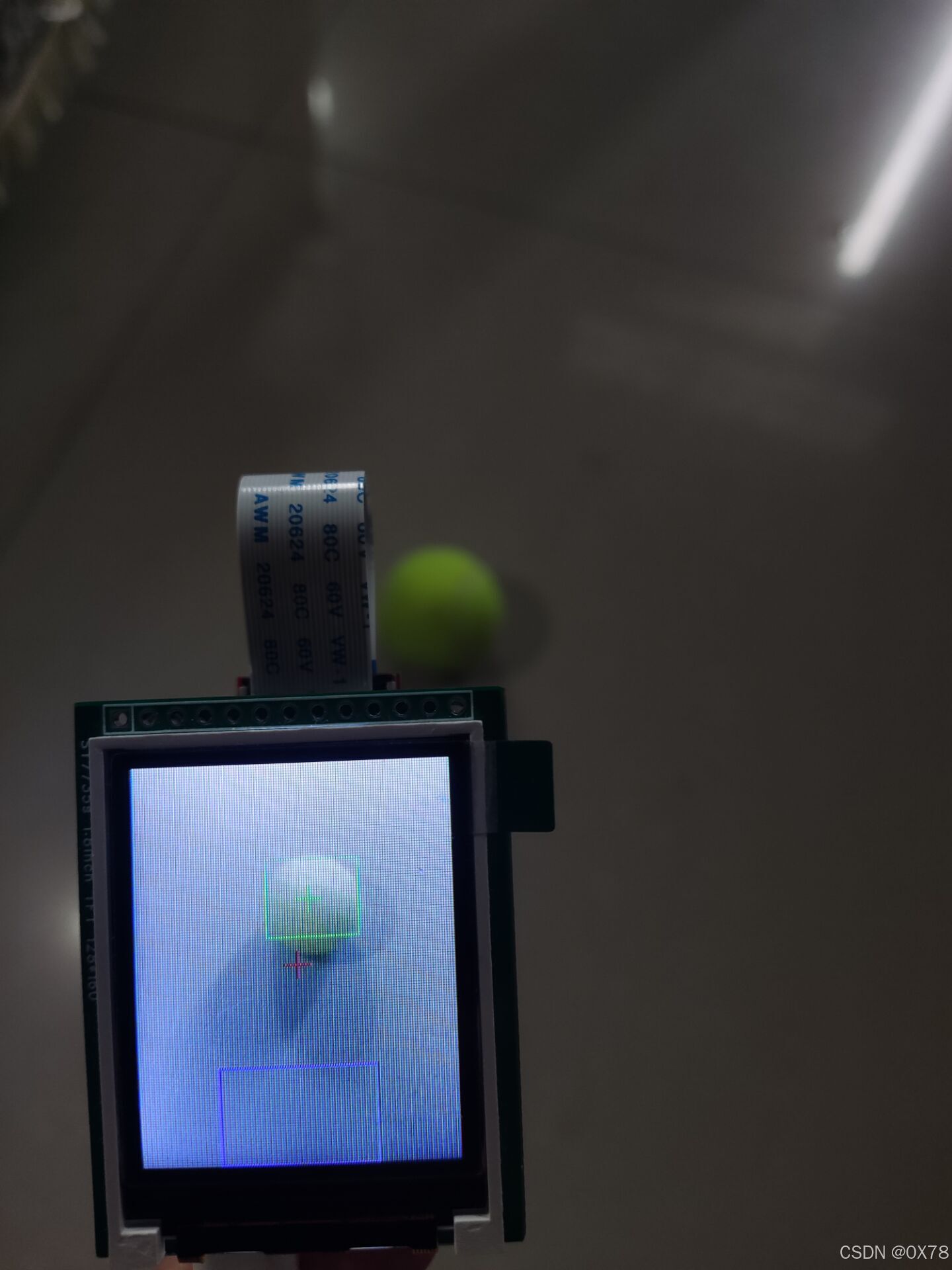
3. 识别效果
这种识别方式对环境,光照要求极高,环境变化后容易识别不准确。
四、多阈值识别加最多像素点识别
1. 阈值获取
使用三、1中描述的阈值获取方法,在不同的环境和光照条件下分别获取相应的阈值,并将这些阈值保存到一个数组中。
2. 代码编写
# 色块监测 例子
#
# 这个例子展示了如何通过find_blobs()函数来查找图像中的色块
# 这个例子查找的颜色是深绿色

import sensor, image, time
import ustruct
# 颜色追踪的例子,一定要控制环境的光,保持光线是稳定的。
green_threshold_num = 4
green_threshold = {}
green_threshold[0] = (48, 100, -128, -8, 20, 127)
green_threshold[1] = (15, 100, -46, -16, 12, 61)
green_threshold[2] = (37, 64, -39, -12, 28, 127)
green_threshold[3] = (46, 98, -31, -16, 14, 127)
# green_threshold   = (15, 100, -46, -16, 12, 61)
#设置绿色的阈值,括号里面的数值分别是L A B 的最大值和最小值(minL, maxL, minA,
# maxA, minB, maxB),LAB的值在图像左侧三个坐标图中选取。如果是灰度图,则只需
#设置(min, max)两个数字即可。

import display
import time
from pyb import UART

# UART 3, and baudrate.
uart = UART(3, 115200)
uart.init(115200, bits=8, parity=None, stop=1)
#RX P5      TX P4
# 初始化串口


sensor.reset() # 初始化摄像头
sensor.set_pixformat(sensor.RGB565) # 格式为 RGB565.
sensor.set_framesize(sensor.QQVGA2) # 使用 QQVGA 速度快一些
sensor.skip_frames(time = 2000) # 跳过2000s,使新设置生效,并自动调节白平衡
sensor.set_auto_gain(False) # 关闭自动自动增益。默认开启的,在颜色识别中,一定要关闭白平衡。
sensor.set_auto_whitebal(False)
#关闭白平衡。白平衡是默认开启的,在颜色识别中,一定要关闭白平衡。
clock = time.clock() # 追踪帧率


lcd = display.SPIDisplay()

# 记录网球不同阈值的数组下标
green_threshold_i = 0
Target = 0
Xmax = 128
Ymax = 160
XSD = 0
uart.write("start")
while(True):


    #lcd.write(sensor.snapshot())  # Take a picture and display the image.
    clock.tick() # Track elapsed milliseconds between snapshots().
    img = sensor.snapshot() # 从感光芯片获得一张图像  宽=128 高=160
    lcd.write(img)  # Take a picture and display the image.

    if green_threshold_i == green_threshold_num:
        # 此处发送数据
        uart.write("Target:" + str(Target) + ";X:" + str(Xmax) + ";Y:" + str(Ymax) + ";TargetX:" + str(img.width()) + ";TargetY:" + str(img.height()) + ";")
        if Target == 1:
            img.draw_circle(Xmax, img.height()-Ymax, 15, color = (255, 0, 0)) # 实际发送坐标(有效坐标)

        # 将发送完的数据清零重新计算
        green_threshold_i = 0
        Target = 0
        Xmax = 128
        Ymax = 160
        XSD = 0
    # 水平方向翻转
    sensor.set_hmirror(True)
    # 垂直翻转图像
    sensor.set_vflip(True)
    blobs = img.find_blobs([green_threshold[green_threshold_i]], pixels_threshold = 50)#invert = 0
    green_threshold_i = green_threshold_i + 1

    #find_blobs(thresholds, invert=False, roi=Auto),thresholds为颜色阈值,
    #是一个元组,需要用括号[ ]括起来。invert=1,反转颜色阈值,invert=False默认 false没有反转
    #不反转。roi设置颜色识别的视野区域,roi是一个元组, roi = (x, y, w, h),代表
    #从左上顶点(x,y)开始的宽为w高为h的矩形区域,roi不设置的话默认为整个图像视野。
    #这个函数返回一个列表,
    # [0]代表识别到的目标颜色区域左上顶点的x坐标,
    # [1]代表左上顶点y坐标,
    # [2]代表目标区域的宽,
    # [3]代表目标区域的高,
    # [4]代表目标区域像素点的个数,[5]代表目标区域的中心点x坐标,[6]代表目标区域中心点y坐标,
    #[7]代表目标颜色区域的旋转角度(是弧度值,浮点型,列表其他元素是整型),
    #[8]代表与此目标区域交叉的目标个数,[9]代表颜色的编号(它可以用来分辨这个
    #区域是用哪个颜色阈值threshold识别出来的)。
    #img.draw_circle(10, 10, 10, color=(0,255,0))
    # img.draw_rectangle(70, 0, 20, 60, color=(255,0,0)) # rect
    # img.draw_rectangle(70, 20, 20, 20, color=(255,0,0)) # rect


    if blobs:
    #如果找到了目标颜色
        for b in blobs:
        #迭代找到的目标颜色区域
            # Draw a rect around the blob.
            if abs(b[3] - b[2]) <= 10 :
                # img.draw_rectangle(b[0:4], color=(0,255,0)) # rect
                #用矩形标记出目标颜色区域
                # img.draw_cross(b[5], b[6], color=(0,255,0)) # cx, cy
                #在目标颜色区域的中心画十字形标记
                #print(b[5], b[6])
                # img.draw_cross(64, 80, color=(255,0,0)) # cx, cy
                Target = 1
                X = b[5]
                Y = img.height() - b[6]
                if b[4] > XSD:
                    # 记录最大且有效的坐标点
                    Xmax = X
                    Ymax = Y
                    XSD = b[4]
                # if green_threshold_i == green_threshold_num - 1:
                #    uart.write("Target:" + str(Target) + ";X:" + str(b[5]) + ";Y:" + str(img.height() - b[6]) + ";TargetX:" + str(img.width()) + ";TargetY:" + str(img.height()) + ";")

                # 如果没有找到目标颜色
    # if Target == 0:
    #    uart.write("Target:" + str(Target) + ";X:" + "0" + ";Y:" + "0" + ";TargetX:" + str(img.width()) + ";TargetY:" + str(img.height()) + ";")

    img.draw_cross(64, 80, color=(255,0,0)) # cx, cy
    img.draw_rectangle(40,100,128-40*2,60, color=(0,0,255))

    # 显示到lcd屏上面
    lcd.write(img)  # Take a picture and display the image.


    #print(clock.fps()) # 注意: 你的OpenMV连到电脑后帧率大概为原来的一半
    #如果断开电脑,帧率会增加
3. 效果演示
我的最新作品,快来一睹为快!
五、训练神经网络目标检测
1. 获取数据集
首先打开OpenMVIDE连接openmv,然后找到(新数据集)
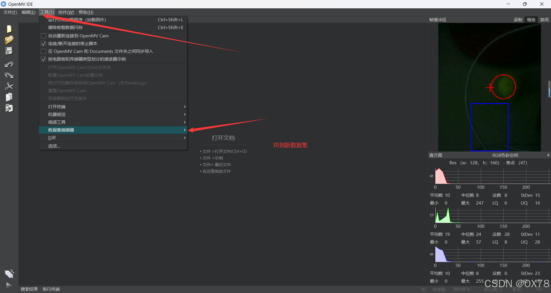
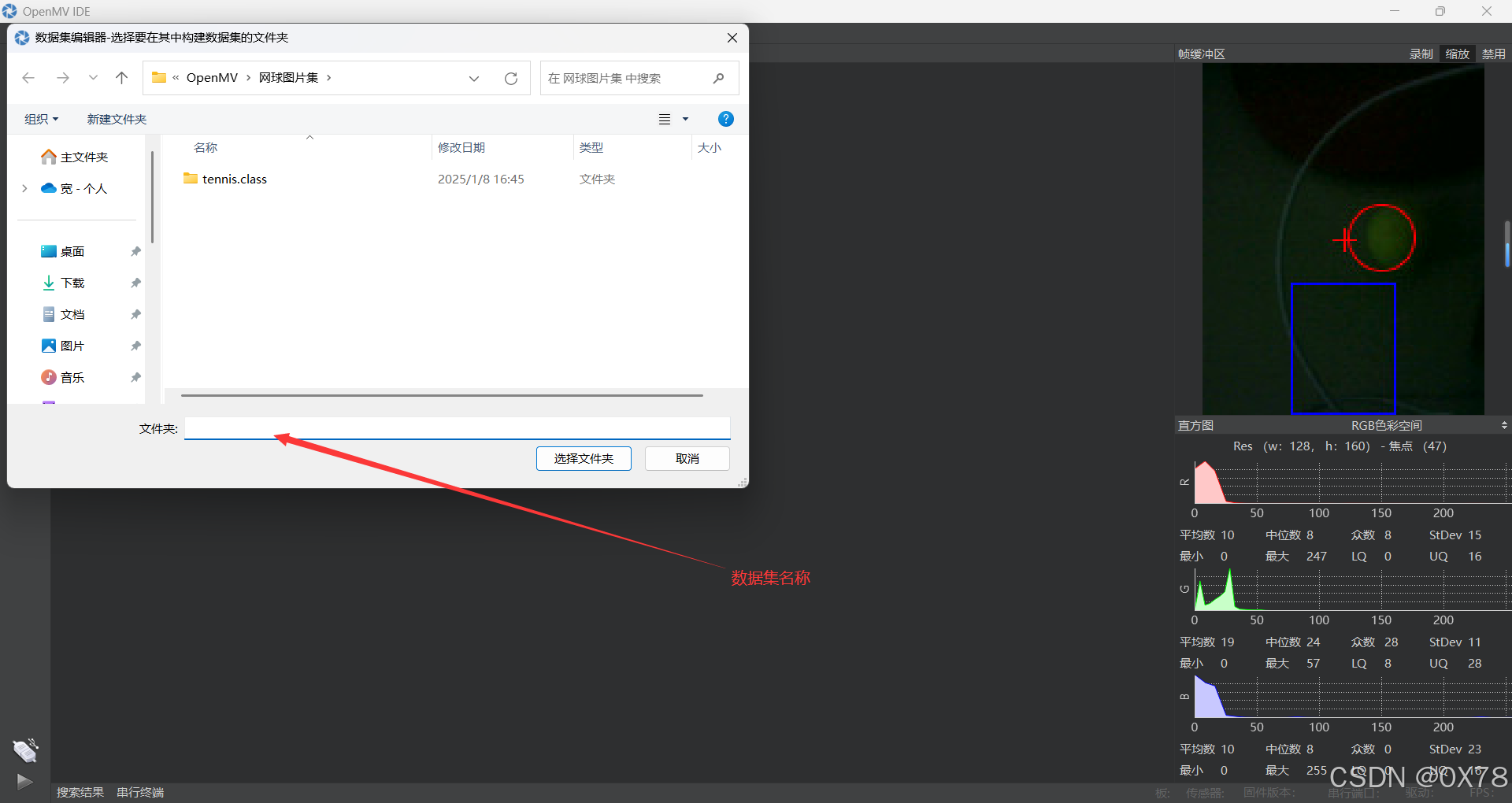
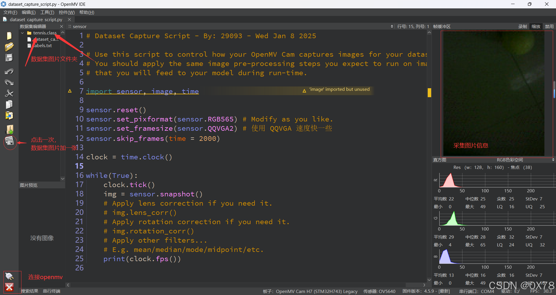
数据集采集使用方法
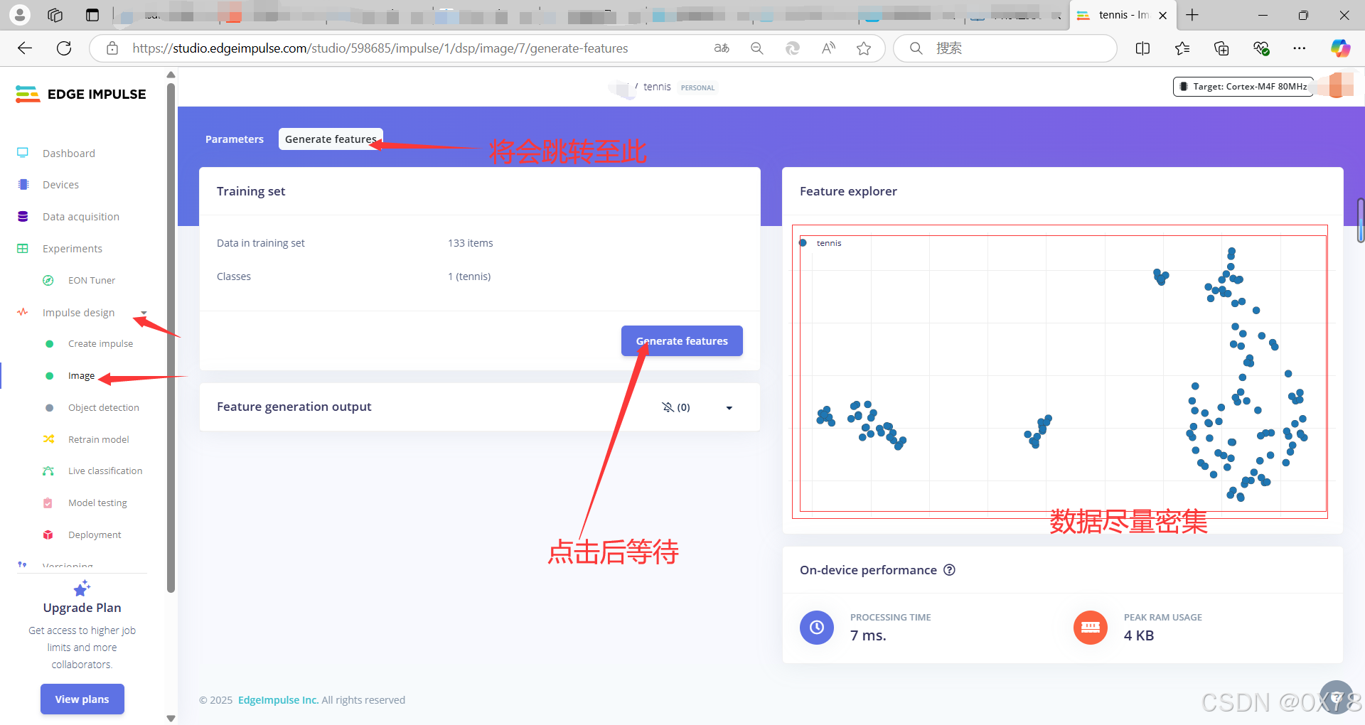
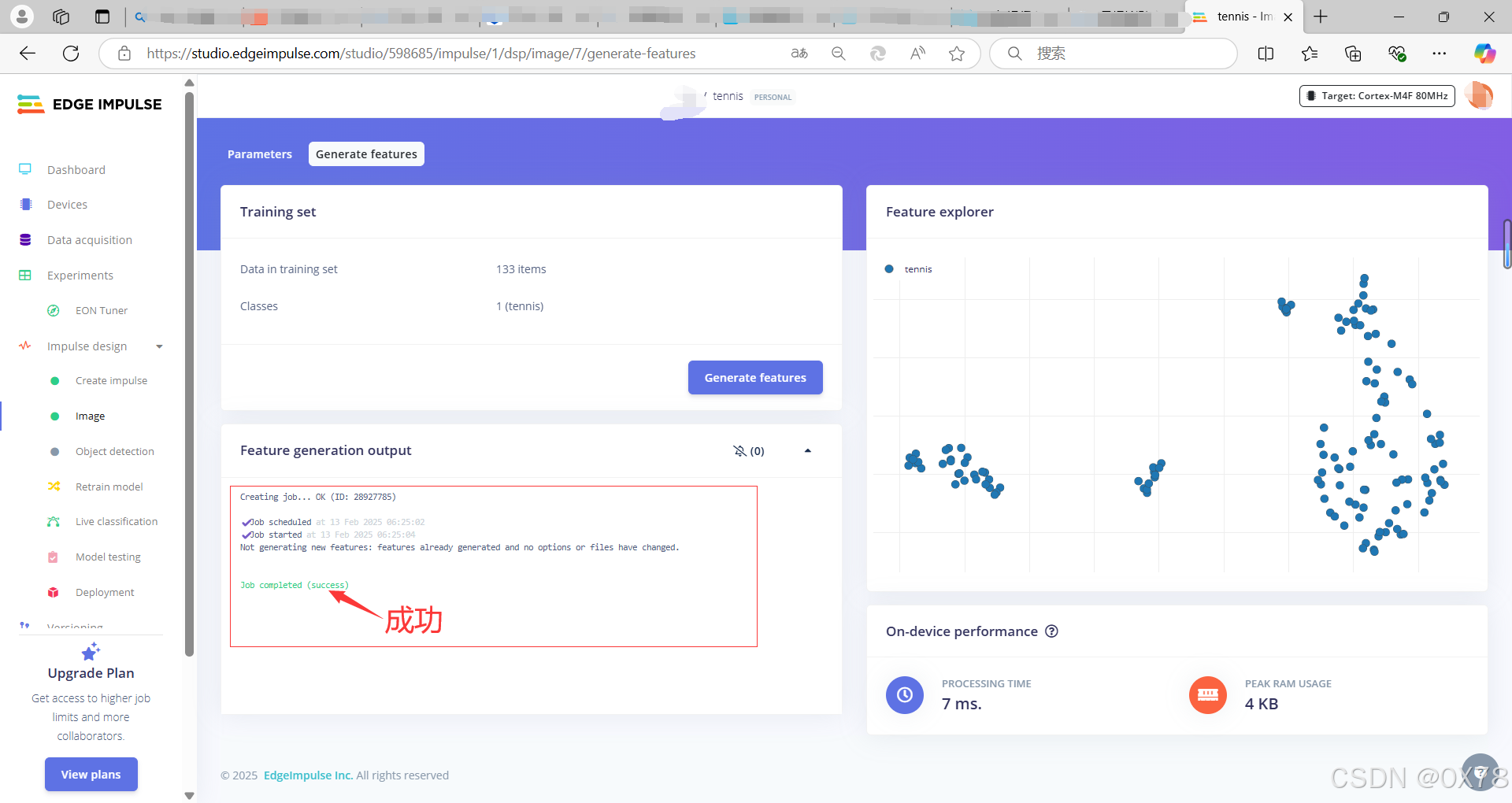
2. 训练神经网络目标检测
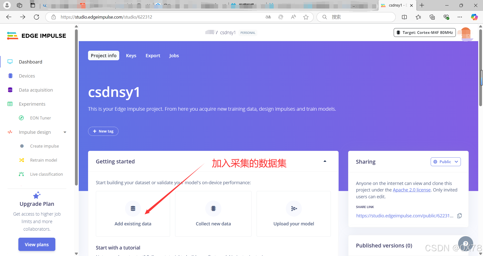
OpenMV合作伙伴EdgeImpulse在线训练网站:https://www.edgeimpulse.com/


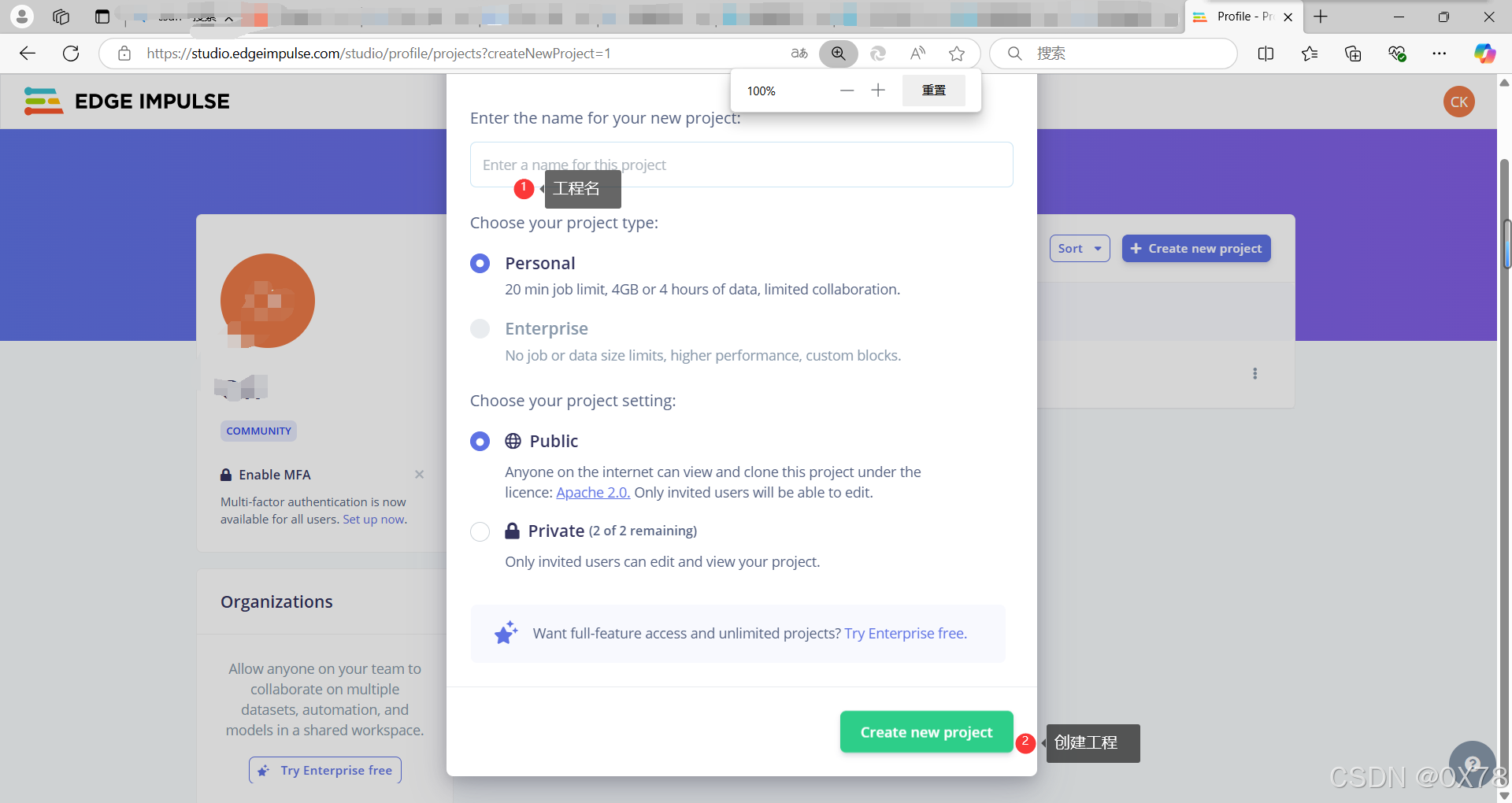
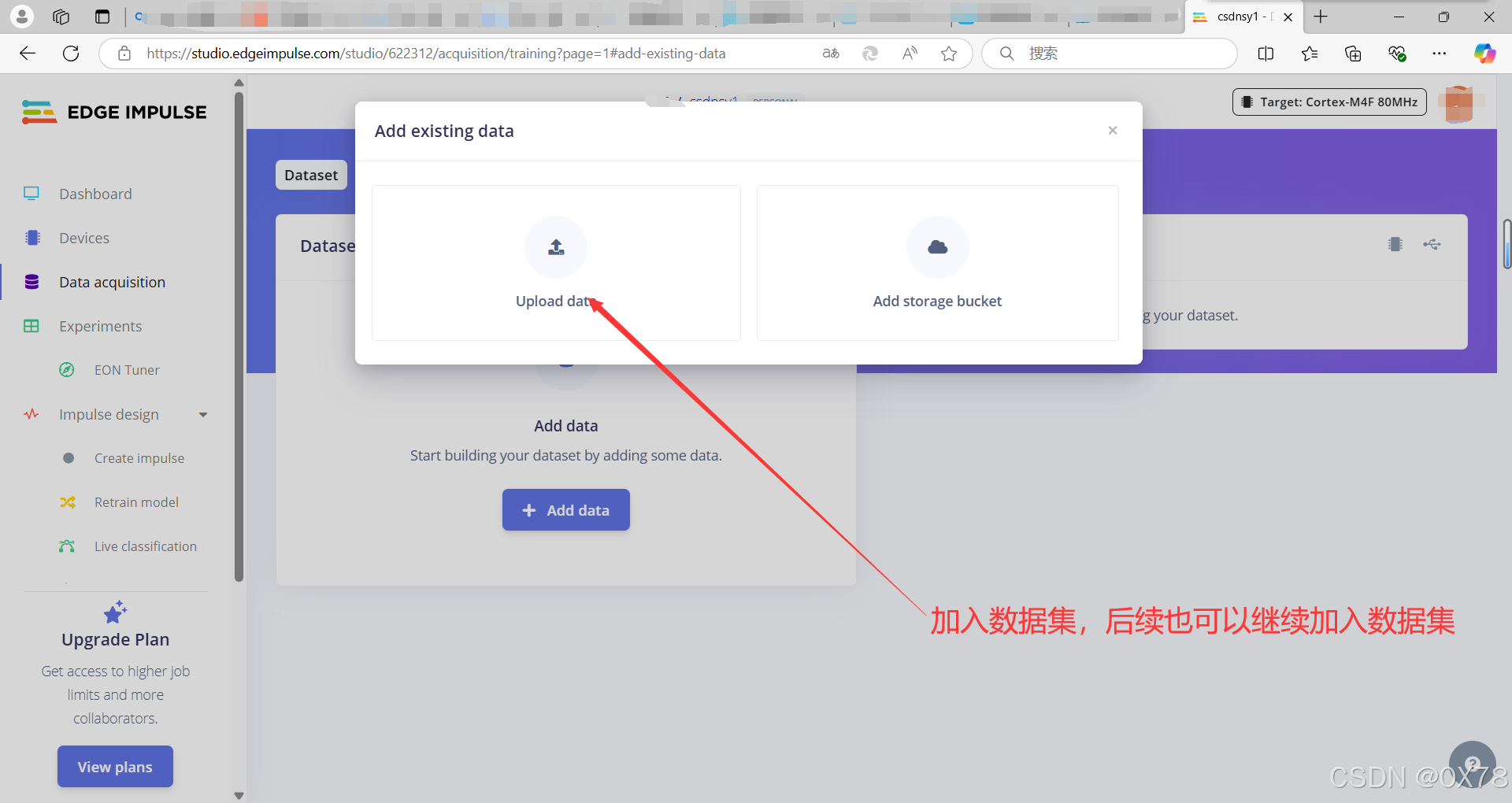
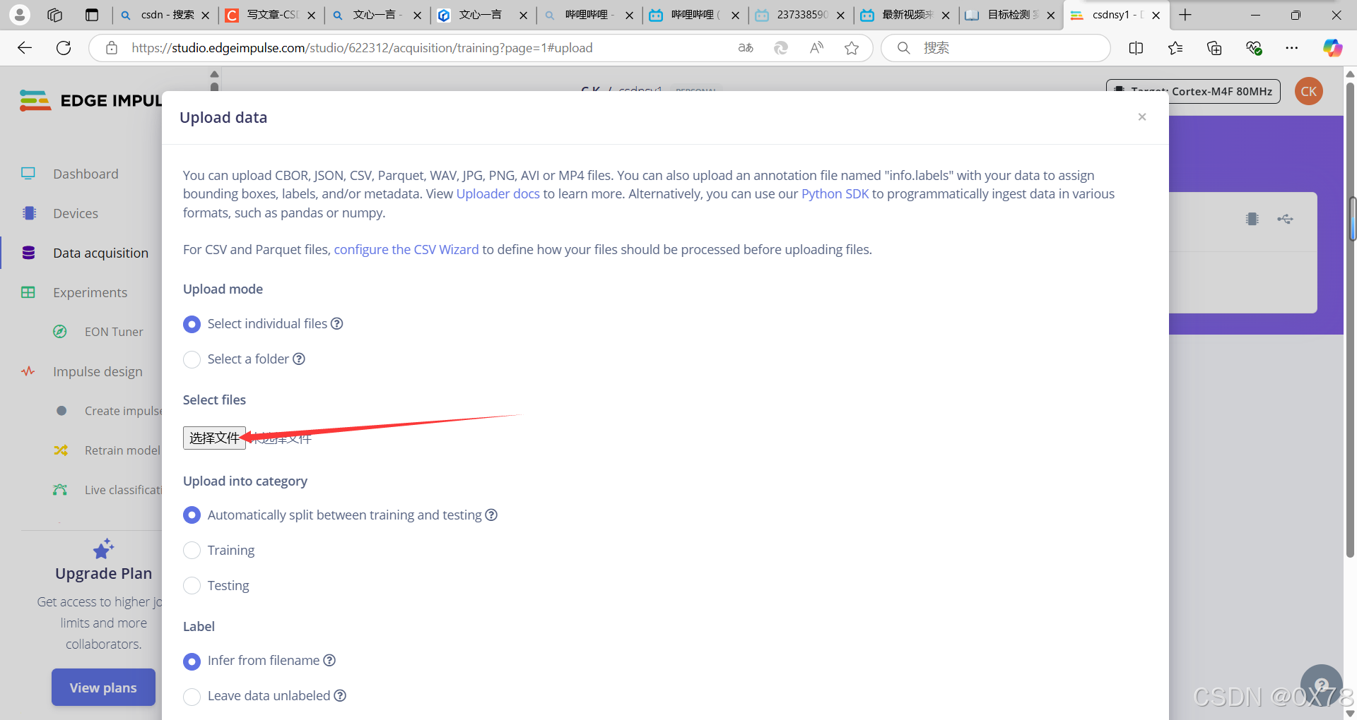
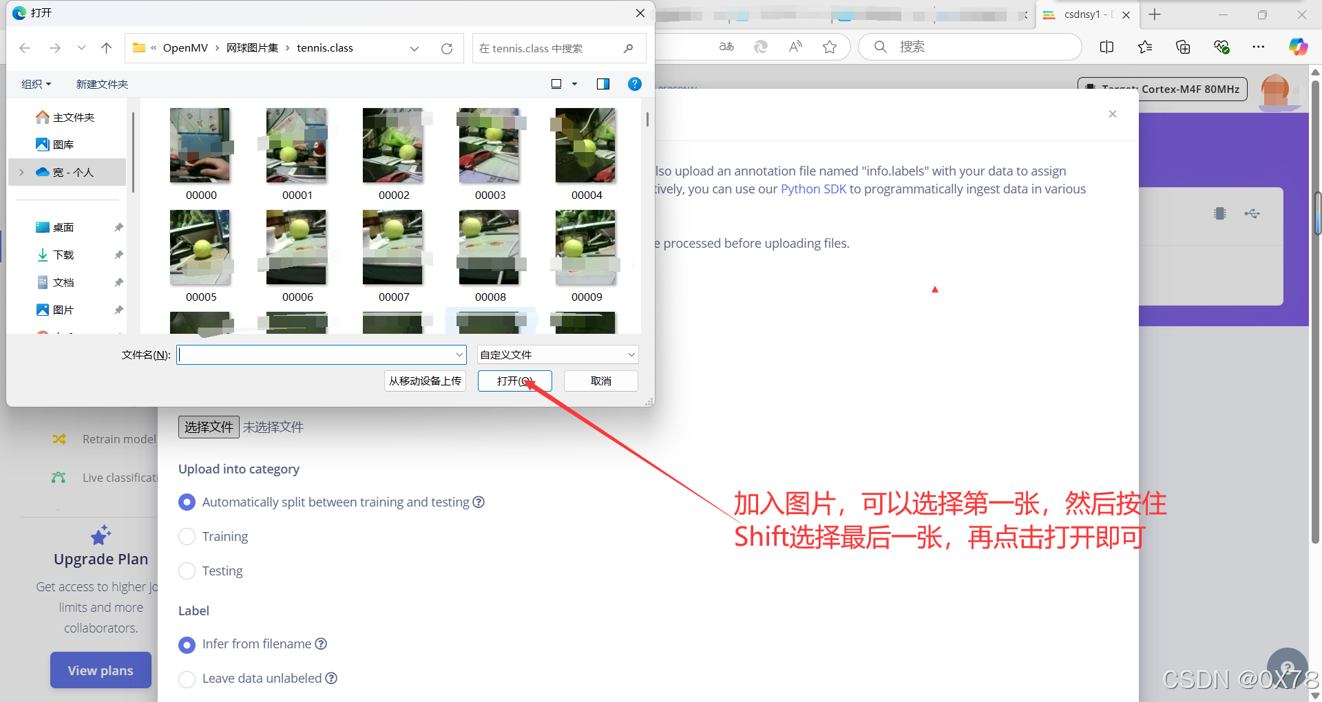
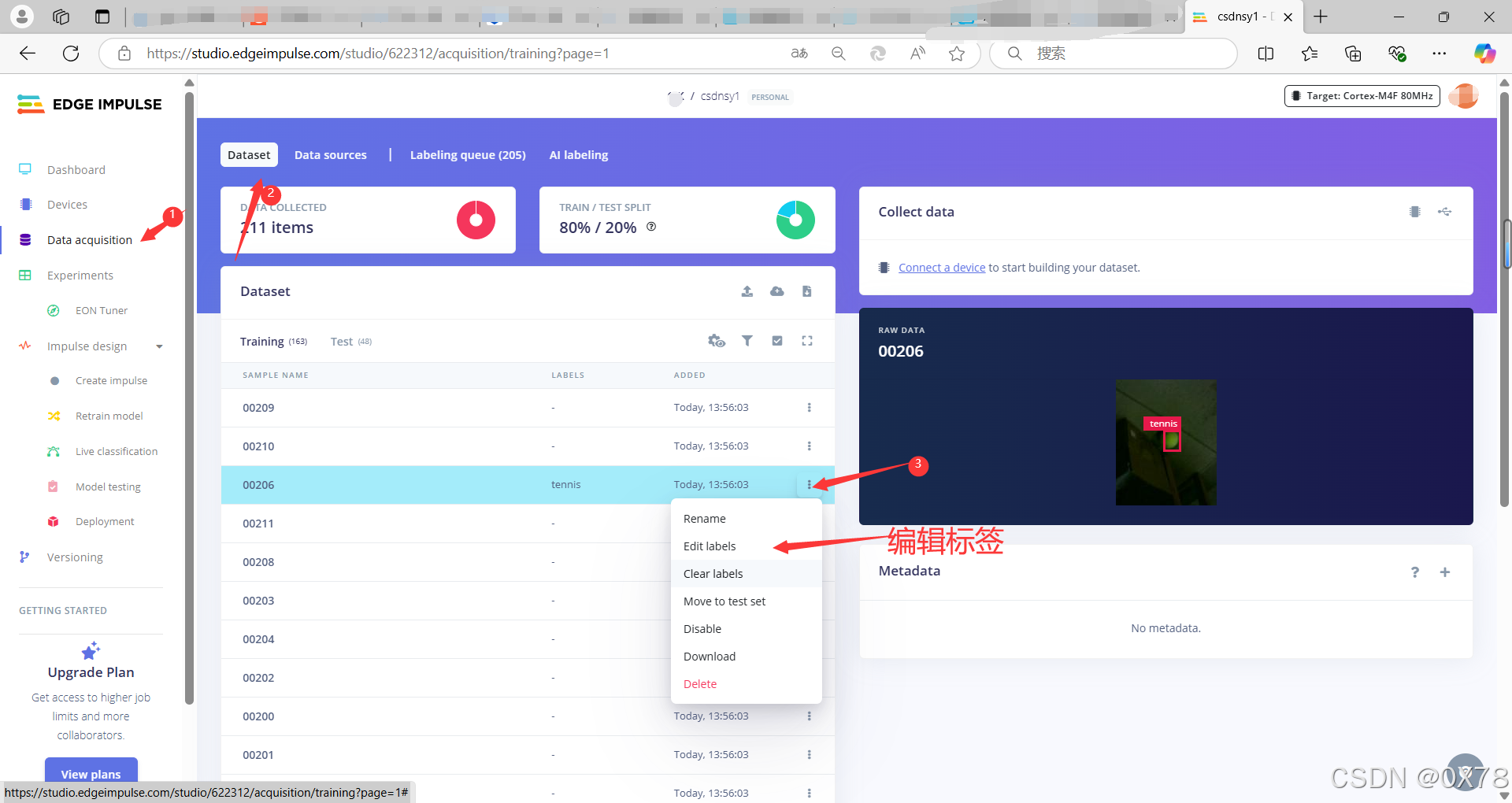
加入数据集
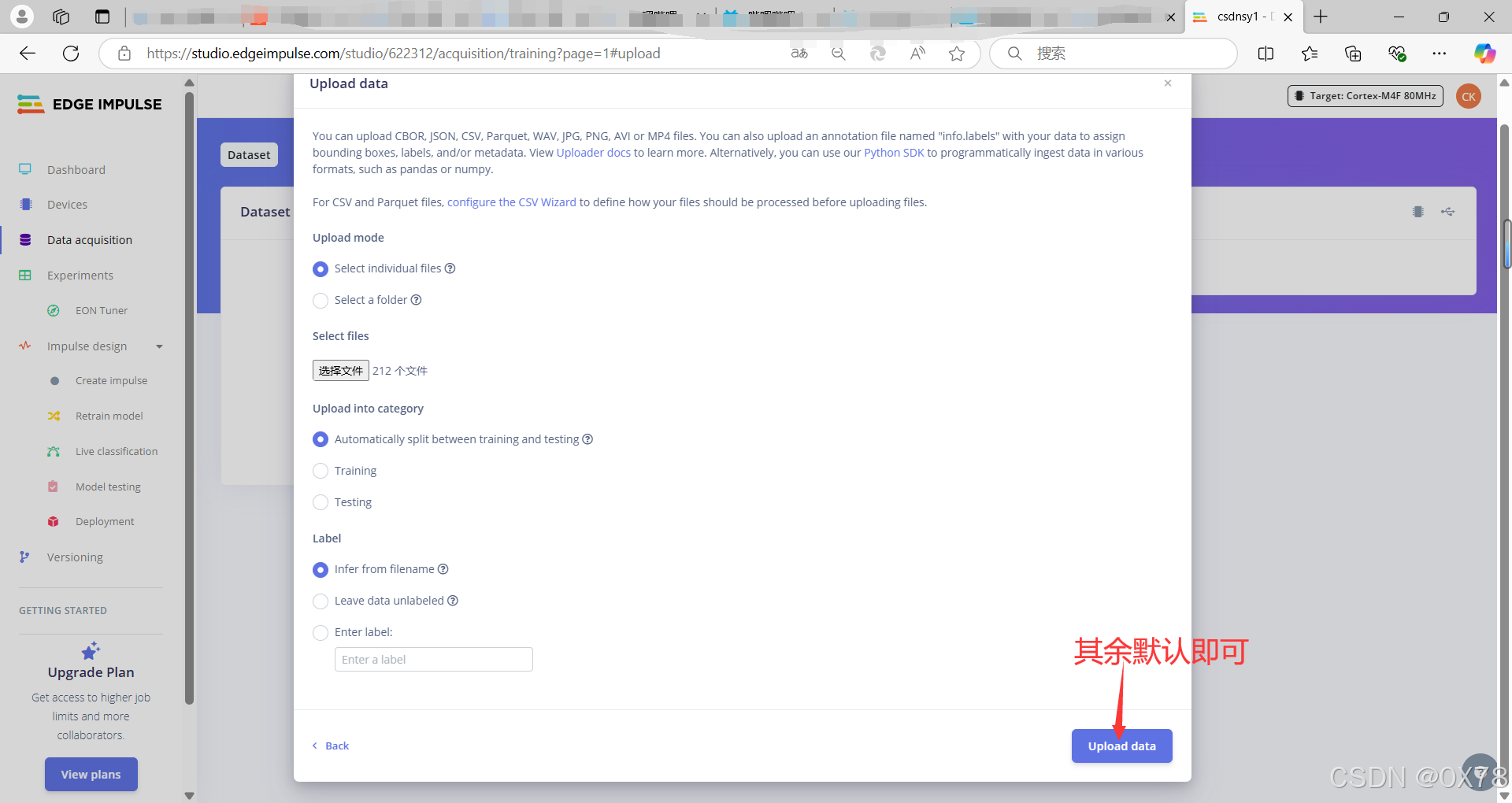
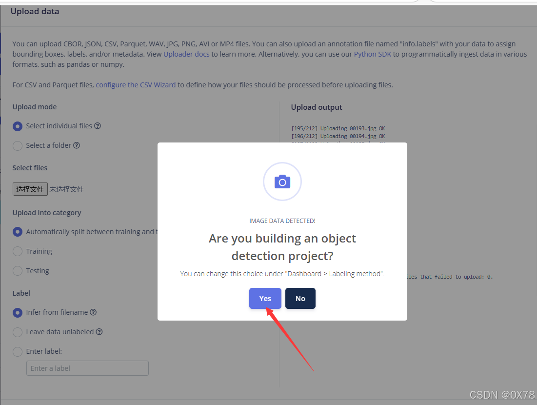
yes等待后,叉掉即可。
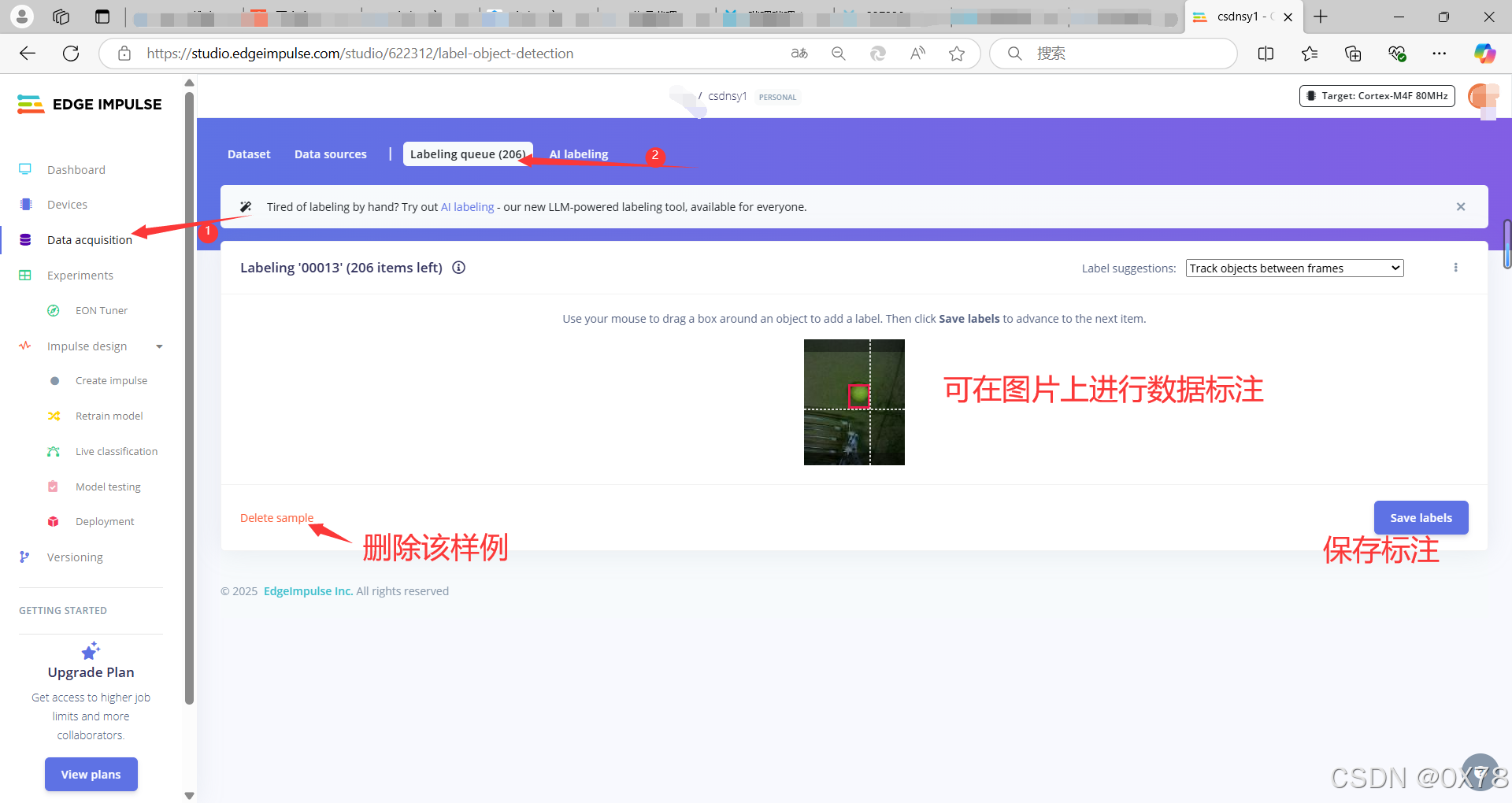
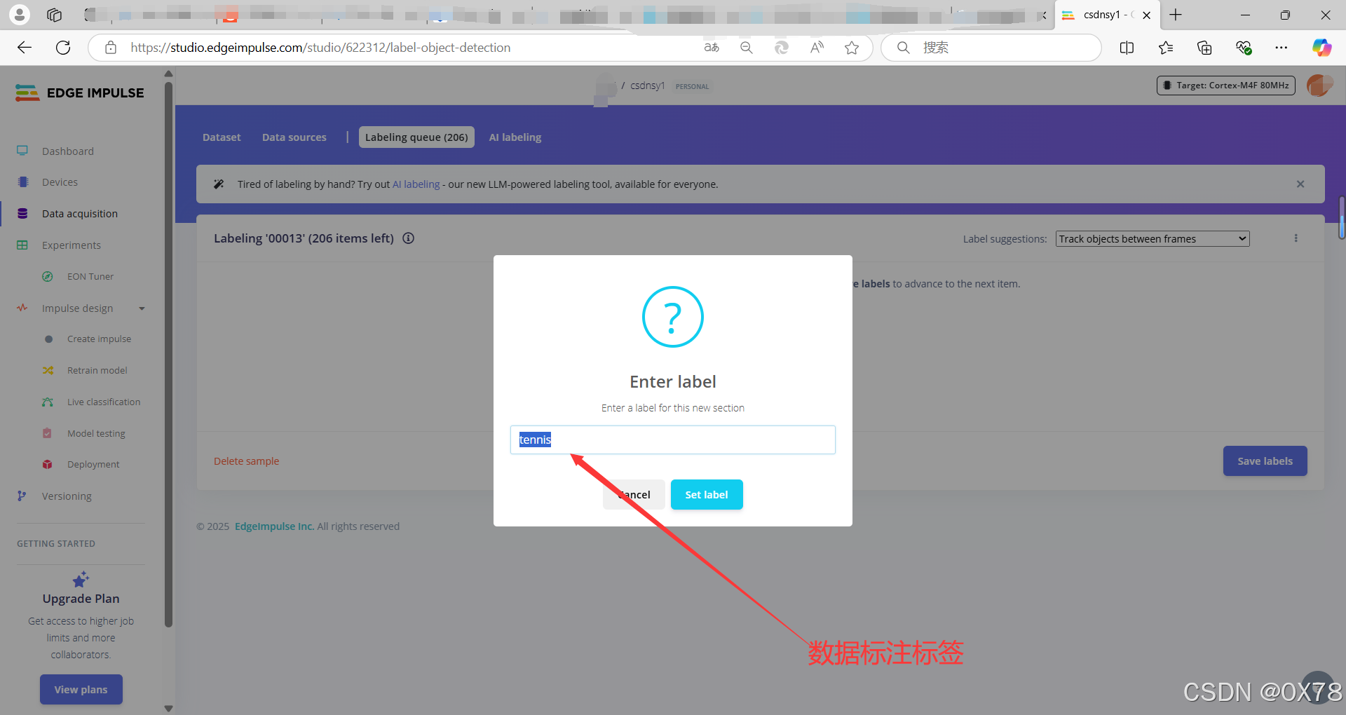
数据标注
标记错误解决方法
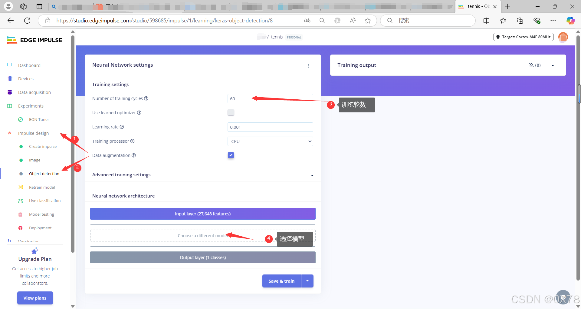
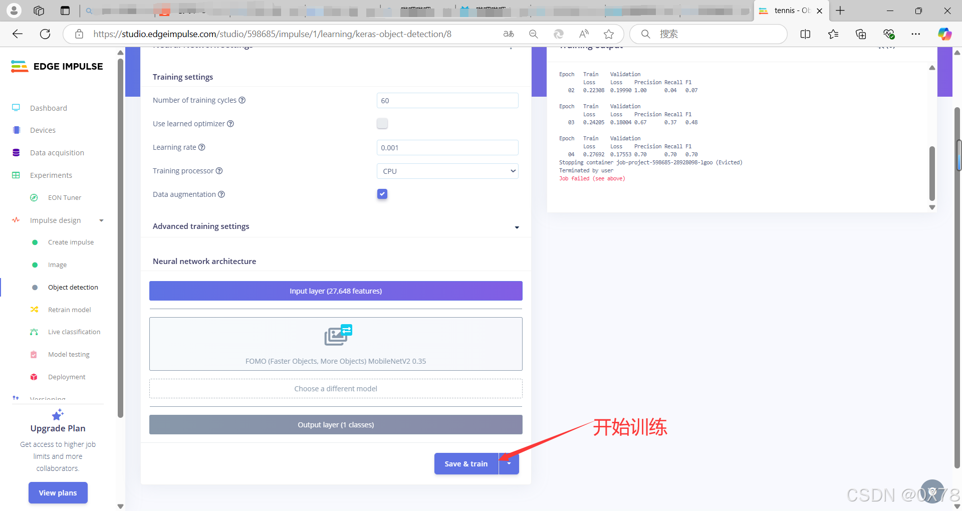
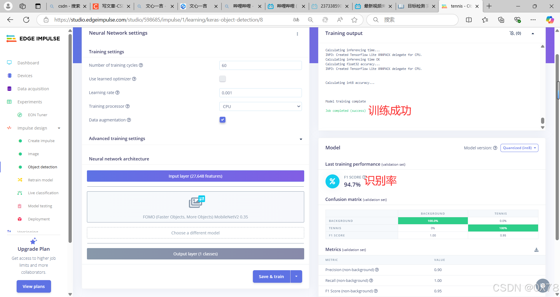
训练模型
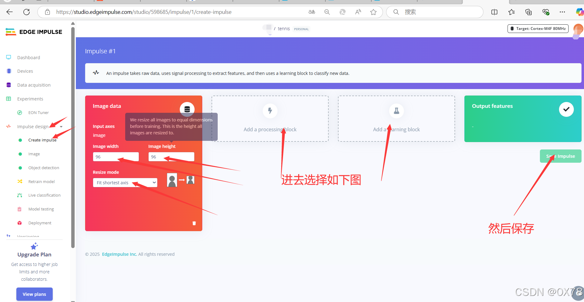
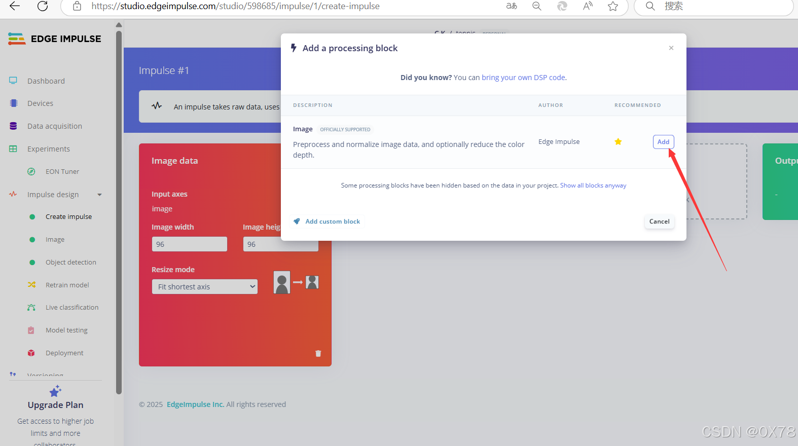
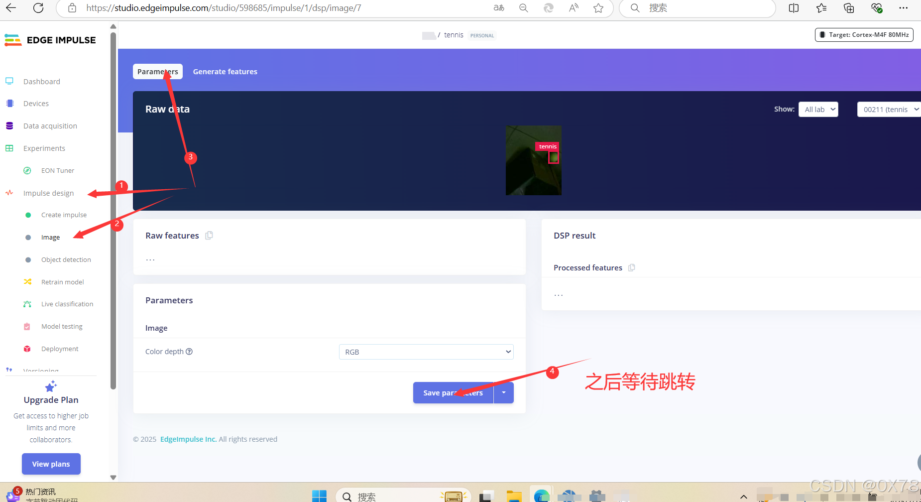
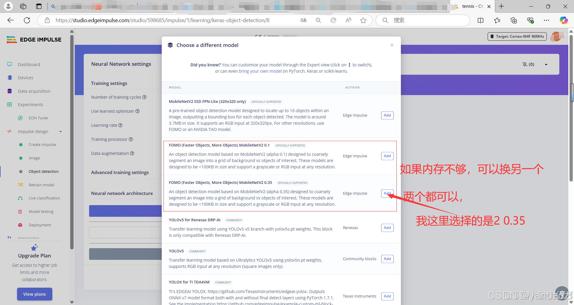
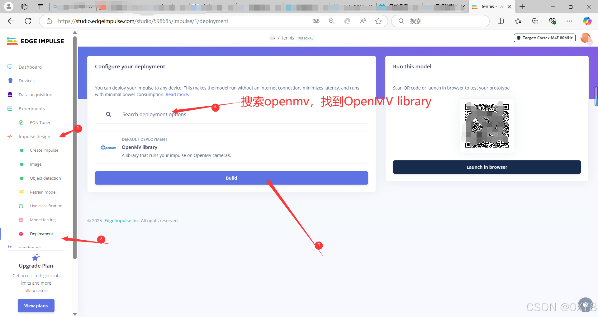
选择模型
导入模型
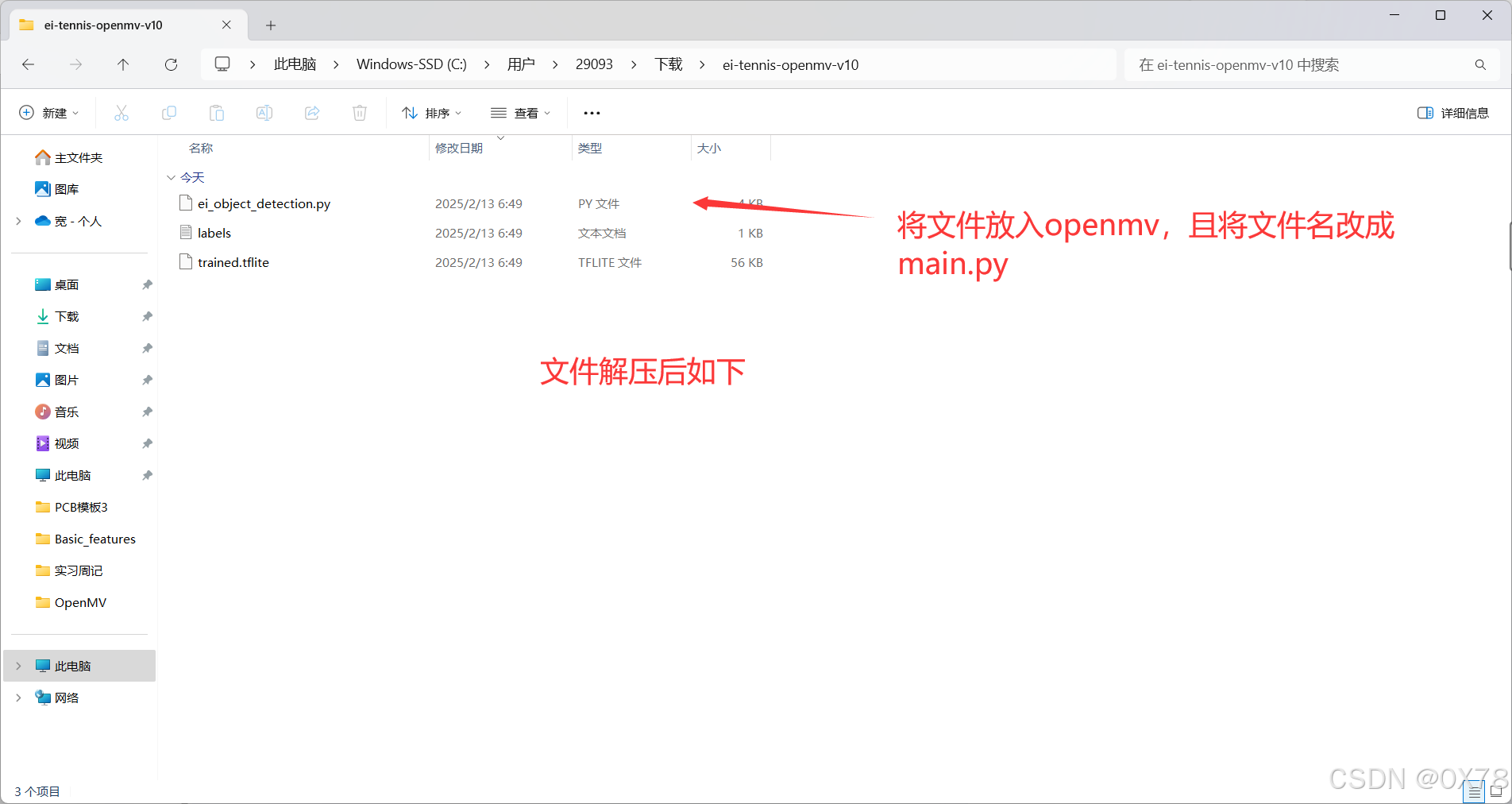
获取模型解压后如下
3. 代码编写
将代码修改,加入lcd屏后串口发送
注释版
# Edge Impulse - OpenMV FOMO Object Detection Example
#
# 这个工作受MIT许可证授权。
# 版权所有 (c) 2013-2024 OpenMV LLC。保留所有权利。
# 许可证详情见:https://github.com/openmv/openmv/blob/master/LICENSE

# 导入必要的库
import sensor, image, time, os, ml, math, uos, gc
from ulab import numpy as np
import ustruct
import display
from pyb import UART

# 配置UART串口,使用UART 3,波特率115200
uart = UART(3, 115200)
uart.init(115200, bits=8, parity=None, stop=1)
# RX连接P5, TX连接P4
# 初始化串口
clock = time.clock() # 用于追踪帧率

# 初始化LCD显示屏
lcd = display.SPIDisplay()

# 初始化摄像头传感器
sensor.reset()                         # 重置并初始化传感器
sensor.set_pixformat(sensor.RGB565)    # 设置像素格式为RGB565(或灰度)
sensor.set_framesize(sensor.QQVGA2)    # 使用QQVGA分辨率以提高速度
sensor.set_windowing((240, 240))       # 设置240x240的窗口
sensor.skip_frames(time=2000)          # 让摄像头调整

# 加载模型
net = None
labels = None
min_confidence = 0.5                   # 设置最小置信度阈值

try:
    # 尝试加载模型,如果剩余内存少于64K,则将模型文件加载到Flash中
    net = ml.Model("trained.tflite", load_to_fb=uos.stat('trained.tflite')[6] > (gc.mem_free() - (64*1024)))
except Exception as e:
    # 如果加载失败,抛出异常
    raise Exception('加载"trained.tflite"失败,是否已将.tflite和labels.txt文件复制到存储设备? (' + str(e) + ')')

try:
    # 尝试加载标签文件
    labels = [line.rstrip('\n') for line in open("labels.txt")]
except Exception as e:
    # 如果加载失败,抛出异常
    raise Exception('加载"labels.txt"失败,是否已将.tflite和labels.txt文件复制到存储设备? (' + str(e) + ')')

# 定义颜色列表,用于绘制检测到的对象边框
colors = [
    (255,   0,   0),
    (  0, 255,   0),
    (255, 255,   0),
    (  0,   0, 255),
    (255,   0, 255),
    (  0, 255, 255),
    (255, 255, 255),
]

# 设置置信度阈值列表
threshold_list = [(math.ceil(min_confidence * 255), 255)]

# 定义后处理函数,用于处理模型输出
def fomo_post_process(model, inputs, outputs):
    # 获取模型的输出形状
    ob, oh, ow, oc = model.output_shape[0]

    # 计算x和y方向的缩放比例
    x_scale = inputs[0].roi[2] / ow
    y_scale = inputs[0].roi[3] / oh
    scale = min(x_scale, y_scale)

    # 计算x和y方向的偏移量
    x_offset = ((inputs[0].roi[2] - (ow * scale)) / 2) + inputs[0].roi[0]
    y_offset = ((inputs[0].roi[3] - (oh * scale)) / 2) + inputs[0].roi[1]

    # 初始化列表,用于存储每个类别的检测结果
    l = [[] for i in range(oc)]

    # 遍历每个输出通道
    for i in range(oc):
        # 将输出通道的数据转换为图像
        img = image.Image(outputs[0][0, :, :, i] * 255)
        # 在图像中查找二值化区域(blobs)
        blobs = img.find_blobs(
            threshold_list, x_stride=1, y_stride=1, area_threshold=1, pixels_threshold=1
        )
        # 遍历每个检测到的区域
        for b in blobs:
            rect = b.rect()  # 获取区域的矩形框
            x, y, w, h = rect
            # 计算区域的置信度
            score = img.get_statistics(thresholds=threshold_list, roi=rect).l_mean() / 255.0
            # 将区域的坐标和尺寸转换回原始图像坐标系
            x = int((x * scale) + x_offset)
            y = int((y * scale) + y_offset)
            w = int(w * scale)
            h = int(h * scale)
            # 将检测结果添加到列表中
            l[i].append((x, y, w, h, score))
    return l

# 重置帧率追踪器
clock = time.clock()

# 初始化变量
Target = 0  # 目标检测标志
Xmax = 0    # 最大X坐标
Ymax = 0    # 最大Y坐标
# 向串口发送开始信号
uart.write("start")
while(True):
    clock.tick()  # 更新帧率追踪器

    # 拍摄一帧图像
    img = sensor.snapshot()
    # 水平翻转图像
    sensor.set_hmirror(True)
    # 垂直翻转图像
    sensor.set_vflip(True)
    # 通过串口发送当前检测状态和目标位置信息
    uart.write("Target:" + str(Target) + ";X:" + str(Xmax) + ";Y:" + str(Ymax) + ";TargetX:" + str(img.width()) + ";TargetY:" + str(img.height()) + ";")
    print("Target:" + str(Target) + ";X:" + str(Xmax) + ";Y:" + str(Ymax) + ";TargetX:" + str(img.width()) + ";TargetY:" + str(img.height()) + ";")
    # 重置变量
    Xmax = 0
    Ymax = 0
    Target = 0
    # 使用模型进行预测,并处理输出结果
    for i, detection_list in enumerate(net.predict([img], callback=fomo_post_process)):
        if i == 0: continue  # 跳过背景类别
        if len(detection_list) == 0: continue  # 如果该类别没有检测结果,则跳过

        # 打印类别标签
        print("********** %s **********" % labels[i])

        # 遍历检测结果
        for x, y, w, h, score in detection_list:
            Target = 1  # 设置目标检测标志
            # 计算中心坐标
            center_x = math.floor(x + (w / 2))
            center_y = math.floor(y + (h / 2))
            # 更新最大X坐标和Y坐标(注意Y坐标需要转换为相对于底部的距离)
            Xmax = center_x
            Ymax = img.height() - center_y
            # 打印检测结果
            print(f"x {center_x}\ty {center_y}\tscore {score}")
            # 在图像上绘制检测到的对象中心
            img.draw_circle((center_x, center_y, 12), color=colors[i])

    # 打印当前帧率
    print(clock.fps(), "fps", end="\n\n")
    # 在图像上绘制一个十字标记和一个矩形框(仅用于演示)
    img.draw_cross(64, 80, color=(255,0,0)) # cx, cy
    img.draw_rectangle(40,100,128-40*2,60, color=(0,0,255))

    # 将图像显示到LCD上
    lcd.write(img)
无注释版
# Edge Impulse - OpenMV FOMO Object Detection Example
#
# This work is licensed under the MIT license.
# Copyright (c) 2013-2024 OpenMV LLC. All rights reserved.
# https://github.com/openmv/openmv/blob/master/LICENSE

import sensor, image, time, os, ml, math, uos, gc
from ulab import numpy as np
import ustruct
import display
from pyb import UART

# UART 3, and baudrate.
uart = UART(3, 115200)
uart.init(115200, bits=8, parity=None, stop=1)
#RX P5      TX P4
# 初始化串口
clock = time.clock() # 追踪帧率


lcd = display.SPIDisplay()

sensor.reset()                         # Reset and initialize the sensor.
sensor.set_pixformat(sensor.RGB565)    # Set pixel format to RGB565 (or GRAYSCALE)
sensor.set_framesize(sensor.QQVGA2) # 使用 QQVGA 速度快一些
sensor.set_windowing((240, 240))       # Set 240x240 window.
sensor.skip_frames(time=2000)          # Let the camera adjust.

net = None
labels = None
min_confidence = 0.5

try:
    # load the model, alloc the model file on the heap if we have at least 64K free after loading
    net = ml.Model("trained.tflite", load_to_fb=uos.stat('trained.tflite')[6] > (gc.mem_free() - (64*1024)))
except Exception as e:
    raise Exception('Failed to load "trained.tflite", did you copy the .tflite and labels.txt file onto the mass-storage device? (' + str(e) + ')')

try:
    labels = [line.rstrip('\n') for line in open("labels.txt")]
except Exception as e:
    raise Exception('Failed to load "labels.txt", did you copy the .tflite and labels.txt file onto the mass-storage device? (' + str(e) + ')')

colors = [ # Add more colors if you are detecting more than 7 types of classes at once.
    (255,   0,   0),
    (  0, 255,   0),
    (255, 255,   0),
    (  0,   0, 255),
    (255,   0, 255),
    (  0, 255, 255),
    (255, 255, 255),
]

threshold_list = [(math.ceil(min_confidence * 255), 255)]

def fomo_post_process(model, inputs, outputs):
    ob, oh, ow, oc = model.output_shape[0]

    x_scale = inputs[0].roi[2] / ow
    y_scale = inputs[0].roi[3] / oh

    scale = min(x_scale, y_scale)

    x_offset = ((inputs[0].roi[2] - (ow * scale)) / 2) + inputs[0].roi[0]
    y_offset = ((inputs[0].roi[3] - (ow * scale)) / 2) + inputs[0].roi[1]

    l = [[] for i in range(oc)]

    for i in range(oc):
        img = image.Image(outputs[0][0, :, :, i] * 255)
        blobs = img.find_blobs(
            threshold_list, x_stride=1, y_stride=1, area_threshold=1, pixels_threshold=1
        )
        for b in blobs:
            rect = b.rect()
            x, y, w, h = rect
            score = (
                img.get_statistics(thresholds=threshold_list, roi=rect).l_mean() / 255.0
            )
            x = int((x * scale) + x_offset)
            y = int((y * scale) + y_offset)
            w = int(w * scale)
            h = int(h * scale)
            l[i].append((x, y, w, h, score))
    return l

clock = time.clock()

Target = 0
Xmax = 0
Ymax = 0
uart.write("start")
while(True):
    clock.tick()

    img = sensor.snapshot()
    # 水平方向翻转
    sensor.set_hmirror(True)
    # 垂直翻转图像
    sensor.set_vflip(True)
    uart.write("Target:" + str(Target) + ";X:" + str(Xmax) + ";Y:" + str(Ymax) + ";TargetX:" + str(img.width()) + ";TargetY:" + str(img.height()) + ";")
    print("Target:" + str(Target) + ";X:" + str(Xmax) + ";Y:" + str(Ymax) + ";TargetX:" + str(img.width()) + ";TargetY:" + str(img.height()) + ";")
    Xmax = 0
    Ymax = 0
    Target = 0
    for i, detection_list in enumerate(net.predict([img], callback=fomo_post_process)):
        if i == 0: continue  # background class
        if len(detection_list) == 0: continue  # no detections for this class?

        print("********** %s **********" % labels[i])

        for x, y, w, h, score in detection_list:
            Target = 1
            center_x = math.floor(x + (w / 2))
            center_y = math.floor(y + (h / 2))
            Xmax = center_x
            Ymax = img.height() - center_y
            print(f"x {center_x}\ty {center_y}\tscore {score}")
            img.draw_circle((center_x, center_y, 12), color=colors[i])

    print(clock.fps(), "fps", end="\n\n")
    img.draw_cross(64, 80, color=(255,0,0)) # cx, cy
    img.draw_rectangle(40,100,128-40*2,60, color=(0,0,255))

    lcd.write(img)  # Take a picture and display the image.
六、串口发送
Target:1;X:<X_COORD>;Y:<Y_COORD>;TargetX:<IMG_WIDTH>;TargetY:<IMG_HEIGHT>;
七、总结
优缺点分析
单阈值识别
- 优点
- 实现简单:代码逻辑相对简单,易于理解和上手,对于初学者来说是一种快速实现目标识别的方法。
- 计算效率高:由于只使用一个固定的颜色阈值进行二值化处理,计算量较小,能保证较高的帧率,实时性较好。
- 缺点
- 对环境要求高:光照、网球材质、表面磨损等因素导致网球颜色变化时,识别准确性会大幅下降,适应性较差。
- 误识别率高:容易将图像中的噪点或类似颜色的其他物体误认为是网球,鲁棒性不足。
多阈值识别加最多像素点识别
- 优点
- 适应性增强:通过设置多个颜色阈值范围,能覆盖网球在不同光照和环境条件下的颜色变化,提高了识别的适应性。
- 减少误识别:增加像素量作为识别条件,有助于排除图像中的噪点和小面积的类似颜色区域,降低误识别率。
- 缺点
- 阈值获取复杂:需要在不同环境和光照条件下分别获取阈值,并保存到数组中,增加了前期准备工作的复杂度。
- 计算量增加:对每个阈值范围分别进行阈值识别,并合并结果,计算量相对单阈值识别有所增加,可能会影响帧率。
训练神经网络目标检测
- 优点
- 识别准确性高:通过大量数据训练得到的模型,能够学习到网球的特征,对不同光照、角度和环境下的网球都有较好的识别效果,鲁棒性强。
- 适应性强:可以适应网球颜色、形状等的变化,对于复杂场景的处理能力优于传统的阈值识别方法。
- 缺点
- 训练成本高:需要获取大量的数据集,并进行标注,训练过程也需要一定的计算资源和时间。
- 模型加载和运行要求高:需要将训练好的模型文件和标签文件复制到存储设备,且对设备的内存和计算能力有一定要求,会影响设备的运行效率。
参考资料
1. 实际道路环境交通标志识别 - 自行训练神经网络目标点检测
接单片机设计:DPJSJ0X78


 651
651

 被折叠的 条评论
为什么被折叠?
被折叠的 条评论
为什么被折叠?
 到【灌水乐园】发言


