


这里写自定义目录标题
Rasterization光栅化
走样
屏幕内的像素点是离散的,二维的,计算机生成的图像最基本的元素就是三角形,如何对其离散化操作?
最简单的想法:一个像素点对应一个坐标点,对这个坐标点采样,看他是否在三角形内。
问题:可以看到明显的锯齿,发生了走样
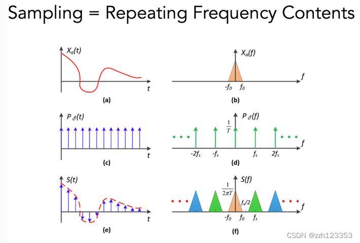
采样是什么?
Sampling = Repeating Frequency Contents
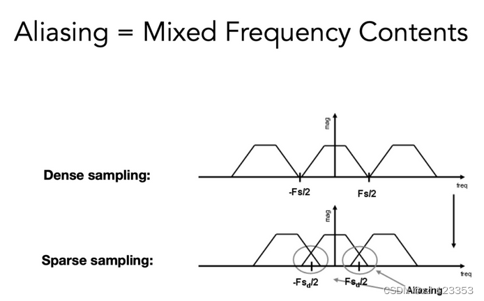
Aliasing = Mixed Frequency Contents
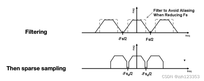
如何避免走样问题?
- 增加采样率
增加频域中的距离,避免发生堆叠
更高的分辨率设备
昂贵、代价大 - 反走样
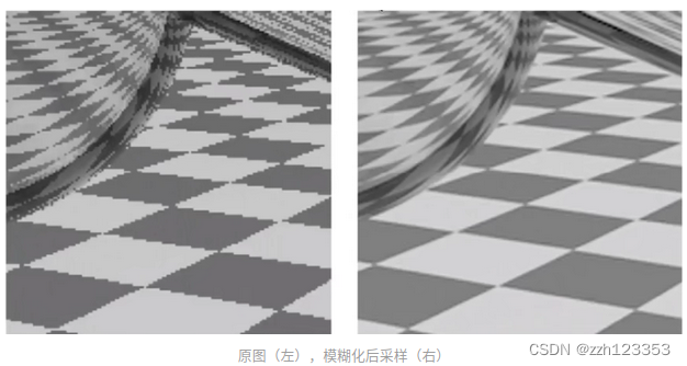
先模糊(卷积)再采样
最理想的状态:像素颜色是负责区域的平均值。
(1)先模糊(滤波),再采样(Blurring/Pre-Filtering Before Sampling):对一个需要显示到屏幕上图形,使用像素中心对图形进行采样,因为像素的离散性质,会不可避免的产生锯齿,如下图所示:
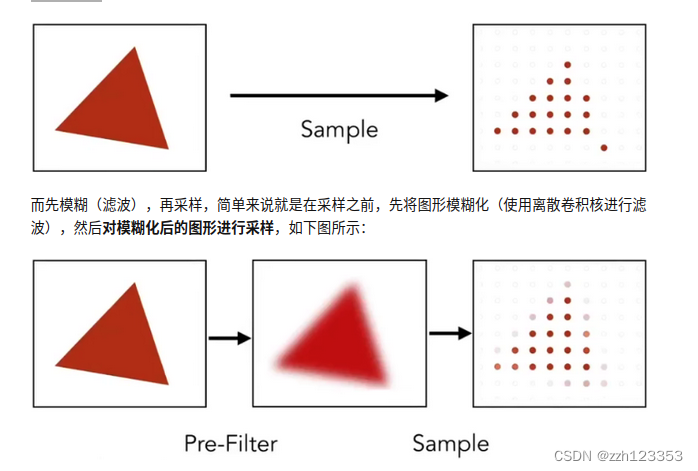
这种方法实际效果还是不错的,只是会将图片变得更模糊,但锯齿的确是减轻很多,如下图所示:
 思考:能否反过来,先采样,再模糊(滤波)?肯定不行,首先,这种行为有个专有名称 Blurred Aliasing(滤波走样),对一个有锯齿的图,模糊化后,图模糊了,但锯齿还在,然后再对这个有锯齿的图进行采样,得到的是一个即模糊,又有锯齿的图,如下图所示
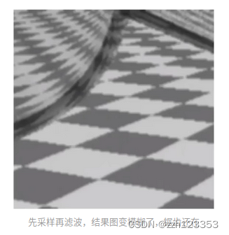
本质原因:进行模糊操作,本质上是通过一个离散卷积核降低图片中颜色变化剧烈的部分,使得这部分像素值是卷积核中像素颜色的平均值,弱化了锯齿的视觉效果,对弱化的锯齿图进行采样,就能得到一个锯齿不那么严重的图,而先采样再模糊,使得模糊失去了其原本的作用。
MSAA
即所谓超采样,依旧是利用了采样的原理,将一个物理像素在逻辑上划分多个子区域,然后对这些子区域的中心进行采样,相当于在逻辑上增加了像素点。比如将一个像素划分为 4x4 个子区域,然后以子区域中心作为采样点,由原来的1个采样点扩充到了16个,使得采样更精确,增加了计算量的同时也进一步减弱了锯齿,如下图所示为一个 4x4 的超采样划分示例:

MSAA采样示例:
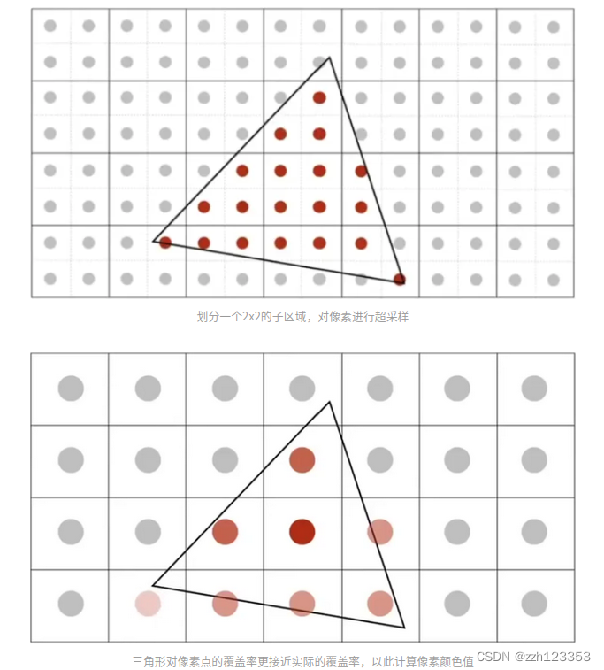
MSAA本质并没有提高屏幕的分辨率,是在逻辑上增加了像素采样点来达到了高分辨率下的低抗锯齿效果,增加采样点使得计算出的三角形对像素的覆盖率更加接近真实的覆盖率,从而更精确的计算像素的颜色之,达到了抗锯齿的效果,和方法先模糊后采样不同,MSAA在抗锯齿处理后,并不会导致图像模糊。
MSAA是以增大计算量为代价的,且增大的计算量可以量化,比如划分了 4x4 的子区域,那就增加了16倍的计算量。
因为实际物理像素RGB的分布可能是不规则的,数量不一,大小不一,所以采样点需要采用合适的分布,合适的采样点分布可以达到更好的覆盖效果,不同像素之间采样点的重合也能减少一定计算量。
Shading
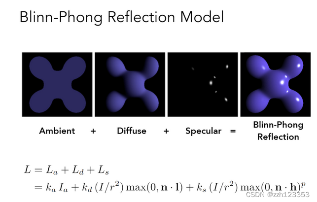
Blinn-Phong Reflectance Model 光照模型 着色模型
-
Diffuse
-
- 和view方向无关
L d = k d ( I / r 2 ) max ( 0 , n ⋅ l ) L_{d}=k_{d}\left(I / r^{2}\right) \max (0, \mathbf{n} \cdot \mathbf{l}) Ld=kd(I/r2)max(0,n⋅l)
- 和view方向无关
-
- k_d:漫反射系数,r:距离,n:单位法向量,l:光源方向
-
Specular
-
- half ector
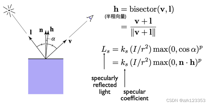
- half ector
-
- k_s:反射系数,p:高光控制系数
-
Ambient
-
- 虚假的
L a = k a I a L_{a}=k_{a} I_{a} La=kaIa
- 虚假的
-
- 提升亮度,真的(全局光照(GI))十分复杂
合并
L
=
L
a
+
L
d
+
L
s
=
k
a
I
a
+
k
d
(
I
/
r
2
)
max
(
0
,
n
⋅
l
)
+
k
s
(
I
/
r
2
)
max
(
0
,
n
⋅
h
)
p
\begin{aligned} L &=L_{a}+L_{d}+L_{s} \\ &=k_{a} I_{a}+k_{d}\left(I / r^{2}\right) \max (0, \mathbf{n} \cdot \mathbf{l})+k_{s}\left(I / r^{2}\right) \max (0, \mathbf{n} \cdot \mathbf{h})^{p} \end{aligned}
L=La+Ld+Ls=kaIa+kd(I/r2)max(0,n⋅l)+ks(I/r2)max(0,n⋅h)p
shading frequencies
- flat shading
每个三角形用一样的法线,shading一次获得颜色值
效果并不好
 *
* - Gouraud shading
对每个顶点做一次shading,中间颜色插值 - Phong Shading
对法线进行插值,对每个点做shading
顶点法线方向的计算:相邻面的法线的平均
插值:Barycentric interpolation
法线向量记得Normalize
Real Time Rendering Pipeline
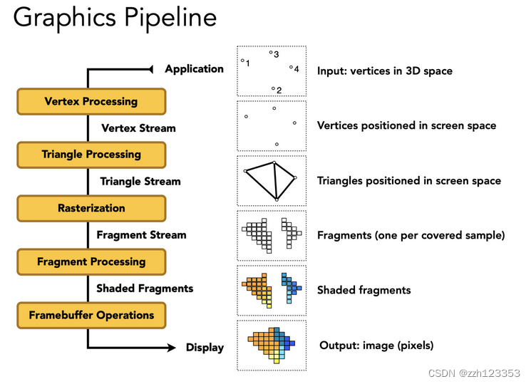
- Vertex Processing
- Model, View, Projection transforms
- Shading, Texture mapping
- Output: Vertex Stream
- Triangle Processing
- Output: Triangle Stream
- Rasterization
- Sampling
- Output: Fragment Stream
- Fragment Processing
- Z-Buffer Visibility Tests
- Shading, Texture mapping
- Output: Shaded Fragments
- Framebuffer Operations
- Output: image (pixels)
Texture Mapping
- 三维物体表面都是二维的
- 纹理:图,有弹性,可以映射到表面
- uv:[0,1]^2
- 三角形每个顶点对应一个uv坐标
- 一张纹理可以使用多次
- 纹理本身设计可以无缝衔接→tilable
- 一种方法:Wang Tiling
Barycentric coordinates 重心坐标->插值
三角形的三个顶点的坐标和内部某个点坐标关系
(
x
,
y
)
=
α
A
+
β
B
+
γ
C
α
+
β
+
γ
=
1
\begin{array}{r} (x, y)=\alpha A+\beta B+\gamma C \\ \alpha+\beta+\gamma=1 \end{array}
(x,y)=αA+βB+γCα+β+γ=1
利用这个关系可以做其他属性的插值
系数的计算:面积比
α
=
−
(
x
−
x
B
)
(
y
C
−
y
B
)
+
(
y
−
y
B
)
(
x
C
−
x
B
)
−
(
x
A
−
x
B
)
(
y
C
−
y
B
)
+
(
y
A
−
y
B
)
(
x
C
−
x
B
)
β
=
−
(
x
−
x
C
)
(
y
A
−
y
C
)
+
(
y
−
y
C
)
(
x
A
−
x
C
)
−
(
x
B
−
x
C
)
(
y
A
−
y
C
)
+
(
y
B
−
y
C
)
(
x
A
−
x
C
)
γ
=
1
−
α
−
β
\begin{aligned} \alpha &=\frac{-\left(x-x_{B}\right)\left(y_{C}-y_{B}\right)+\left(y-y_{B}\right)\left(x_{C}-x_{B}\right)}{-\left(x_{A}-x_{B}\right)\left(y_{C}-y_{B}\right)+\left(y_{A}-y_{B}\right)\left(x_{C}-x_{B}\right)} \\ \beta &=\frac{-\left(x-x_{C}\right)\left(y_{A}-y_{C}\right)+\left(y-y_{C}\right)\left(x_{A}-x_{C}\right)}{-\left(x_{B}-x_{C}\right)\left(y_{A}-y_{C}\right)+\left(y_{B}-y_{C}\right)\left(x_{A}-x_{C}\right)} \\ \gamma &=1-\alpha-\beta \end{aligned}
αβγ=−(xA−xB)(yC−yB)+(yA−yB)(xC−xB)−(x−xB)(yC−yB)+(y−yB)(xC−xB)=−(xB−xC)(yA−yC)+(yB−yC)(xA−xC)−(x−xC)(yA−yC)+(y−yC)(xA−xC)=1−α−β
利用重心坐标插值三角形顶点的任何属性,注意:如果三角形经过投影后,重心坐标可能会改变。所以如果要插值属性,一定要在三维空间中利用重心坐标插值,不要投影后才插值。
问题1:Texture Magnification 纹理太小怎么办??->插值
- 纹理像素: texel
- 多个pixel映射到了同一个texel
- 解决:
- Nearest
- Bilinear
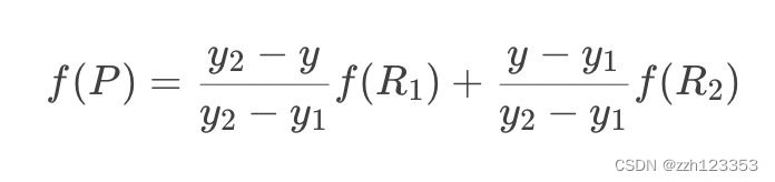
- Bilinear插值lerp
- 水平+竖直插值->双线性插值
- 最近四点插值
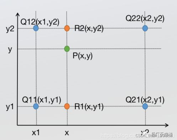
先在x方向插值:
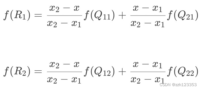
然后在y方向插值
- Bicubic双向三次插值
- 周围16个点做三次插值,利用BiCubic基函数求出16个像素点的权重,像素(x,y)的值就等于16个像素点的加权叠加
- 运算量更大,结果更好

问题2:Texture Magnification纹理太大怎么办?
- 一个pixel对应了多个texel->采样频率不足导致摩尔纹+锯齿(走样)
- 解决:
- SuperSampling
- 过于浪费!
- 只需要得到对应区域的平均值
- MipMap
- 每一次长宽各减半 D=0,1,2,…
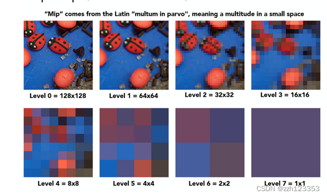
level 0代表的是原始texture,也是精度最高的纹理,随着level的提升,每提升一级将4个相邻像素点求均值合为一个像素点,因此越高的level也就代表了更大的footprint的区域查询。接下来要做的就是根据屏幕像素的footprint大小选定不同level的texture,再进行点查询即可,而这其实就相当于在原始texture上进行了区域查询!
- 每一次长宽各减半 D=0,1,2,…
- SuperSampling
那么如何去确定使用哪个level的texture呢?利用屏幕像素的相邻像素点估算footprint大小再确定level D!如下图:

在屏幕空间中取当前像素点的右方和上方的两个相邻像素点(4个全取也可以),分别查询得到这3个点对应在Texture space的坐标,计算出当前像素点与右方像素点和上方像素点在Texture space的距离,二者取最大值,计算公式如图中所示,那么level D就是这个距离的log2值 (D = log2L) ! 这不难理解,读者可以具体取几个例子比如L = 1,L = 2,L = 4,看看是否符合这样的计算即可。
但是这里D值算出来是一个连续值,并不是一个整数,有两种对应的方法:
1 四舍五入取得最近的那个level D
2 利用D值在 向下和向上取整的两个不同level进行3线性插值
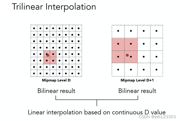
所谓3线性插值,就是在向下取整的D level上进行一次双线性插值(前文提过),再在D+1 level之上进行一次双线性插值,这二者数据再根据实际的连续D值在向下和向上取整的两个不同level之间的比例,再来一次线性插值,而这整体就是一个三线性插值了。
负载:是一个等比数列,会有多余1/3的空间存储这些MipMap
- 缺陷:
1.适合方块查询,显然不能适应大多数情况
2.解决方案:各向异性过滤
Application of Texture
texture = memory + range query (filtering)
- General method to bring data to fragment calculations
Many applications - Environment lighting - Environment Map
- 环境光贴图
- 例子:Utah Teapot
- 经典:Stanford Bunny,Cornell Box
- Spherical Environment Map
- 球心:世界中心
- 一个问题:拉伸,想象地球仪展开
- 解决方法:Cube Map
- Cube Map:立方体表面,从球心到球面的投影向外
- 扭曲更少,但是Need dir->face computation,计算量更大
- Store microgeometry
-
Textures can affect shading! → define height/normal → Bump / Normal Map
- 两者类似,都可以以假乱真
- 改变表面的法线
-
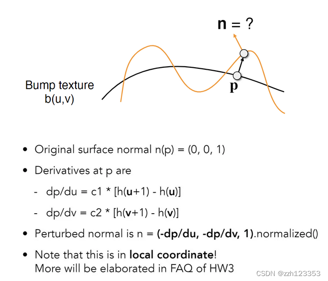
Bump Mapping 凹凸贴图
Bump Mapping的Texture记录了高度移动
- 不改变几何信息
- 逐像素扰动法线方向
- 高度 offset 相对变化,从而改变法线方向
- 计算法线方向:切线的垂直方向
-
Displacement mapping 位移贴图
- 输入相同(Texture与Bump Mapping可共用)
- 改变几何信息,对顶点做位移
- 相比上更逼真,要求模型足够细致,运算量更高
- DirectX有Dynamic的插值法,对模型做插值,使得初始不用过于细致
-
- Procedural textures
- 3D Procedural Noise + Solid Modeling
- 定义空间中任意点的颜色
- 噪声+映射→
- Perlin Noise
- 3D Procedural Noise + Solid Modeling
- Provide Precomputed Shading
- Ambient occlusion texture map
- 计算好的环境光遮蔽贴图
- 空间换时间
- Ambient occlusion texture map
- Solid modeling & Volume rendering
- 三维渲染
Shadow mapping
光栅化下对全局光线传输、阴影的处理十分麻烦。
- draw shadows using rasterization
- An Image-space Algorithm
- 不需要场景的几何信息
- 有走样现象
- 思想:the points NOT in shadow must be seen both by the light and by the camera
步骤:
- Pass 1: Render from Light
- Depth image from light source → shadow map
- Pass 2A: Render from Eye
- Standard image (with depth) from eye
- Pass 2B: Project to light
- Project visible points in eye view back to light source
- visible to light source → color
- blocked → shadow
感觉每个光源对每个静态场景有一个shadow map
应用:
- Project visible points in eye view back to light source
- 几乎所有3D游戏
问题:
- 走样、分辨率
- 数值精度问题
- Involves equality comparison of floating point depth values means issues of scale, bias, tolerance
- 只能点光源、硬阴影
Geometry
几何的表达方式
-
Implicit(隐式)
- Based on classifying points
- Sampling Can Be Hard
- Inside/Outside Tests Easy
- 种类
- algebraic surface
- 最直接的,用数学公式
- 不直观
- Constructive Solid Geometry(CSG)
- 基本形状的布尔操作组合成复杂形状
- Combine implicit geometry via Boolean operations
- distance functions
- 相关:Signed Distance Field
- 解析形式表达
- level sets (水平集)
- Grid方式描述distance
- 例子:CT扫描
- Fractals
- 自相似
- 递归
- …
- algebraic surface
Pros:
• compact description (e.g., a function)
• certain queries easy (inside object, distance to surface)
• good for ray-to-surface intersection (more later)
• for simple shapes, exact description / no sampling error
• easy to handle changes in topology (e.g., fluid)
Cons:
• difficult to model complex shapes
-
Explicit(显式)
- All points are given directly or via parameter mapping
- Sampling Is Easy
- Inside/Outside Test Hard
- 种类
- point cloud
- 一堆点
- 可以表示任何几何
- Useful for LARGE datasets (>>1 point/pixel)
- Often converted into polygon mesh
- Difficult to draw in undersampled regions
- triangle/polygon mesh
- Store vertices & polygons (often triangles or quads)
- More complicated data structures
- Perhaps most common representation in graphics
- 例子:.obj格式
- Just a text file that specifies vertices, normals, texture coordinates and their connectivities
- subdivision, NURBS
- Bezier surfaces
- subdivision surfaces
- NURBS
- …
- point cloud
No “Best” Representation, Each choice best suited to a different task/type of geometry
More Implicit Representations in Computer Graphics
曲线
贝塞尔曲线
一条由四个点(其实是任意≥3个点)定义的曲线:
- p0和p3定义起点和终点
- p1和p2定义起点与终点的切线方向(与p0和p3一起)
Evaluating Bézier Curves (de Casteljau Algorithm)
例子:3点(quadratic Bezier)
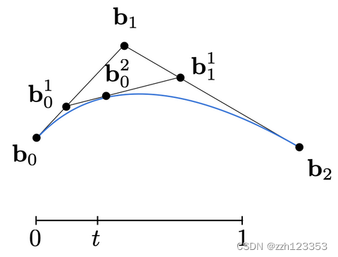
4点曲线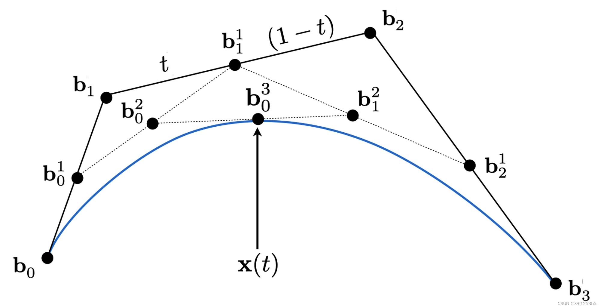
 计算方法:
计算方法:
 一些性质:
一些性质:

- 仿射变换前后统一
- 凸包性质:形成的曲线一定在控制点形成的凸包内
高阶贝塞尔曲线很难控制,任何一个点就能影响全局
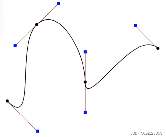
改善→Piecewise Bézier Curves
- Bezier Curve Edit
- chain many low-order Bézier curve
- 例如:Piecewise cubic Bézier
- 每次四个控制点
- 保证光滑(切线不突变):内部控制点前后的切线点共线
连续性定义:
- C^0连续:无断点
- C^1连续:无突变
Spline (样条):a continuous curve constructed so as to pass through a given set of points and have a certain number of continuous derivatives. (a curve under control)
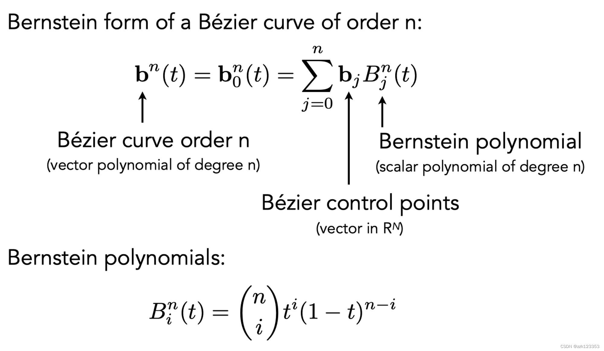
B-splines
- basis splines 基函数样条
- Bernstein Polynomial作为基函数,
- 满足局部性
- 可能是图形学里面最复杂的一部分
- 是贝塞尔曲线的超集
曲面
贝塞尔曲面
两个不同时间t(u,v)
4x4个点,四条4个控制点的贝塞尔曲线,取同一时间(比如说u)获得四个控制点,取时间v,即获得最后的曲面上的点
Mesh
更广泛的还是Mesh
Mesh Operations: Geometry Processing
- Mesh subdivision 细分 upsampling
- Increase resolution
- Mesh simplification 简化 downsampling
- Decrease resolution
- Try to preserve shape/appearance
- Mesh regularization 正规化
- (不会出现特别奇怪的三角形)
- Modify sample distribution to improve quality
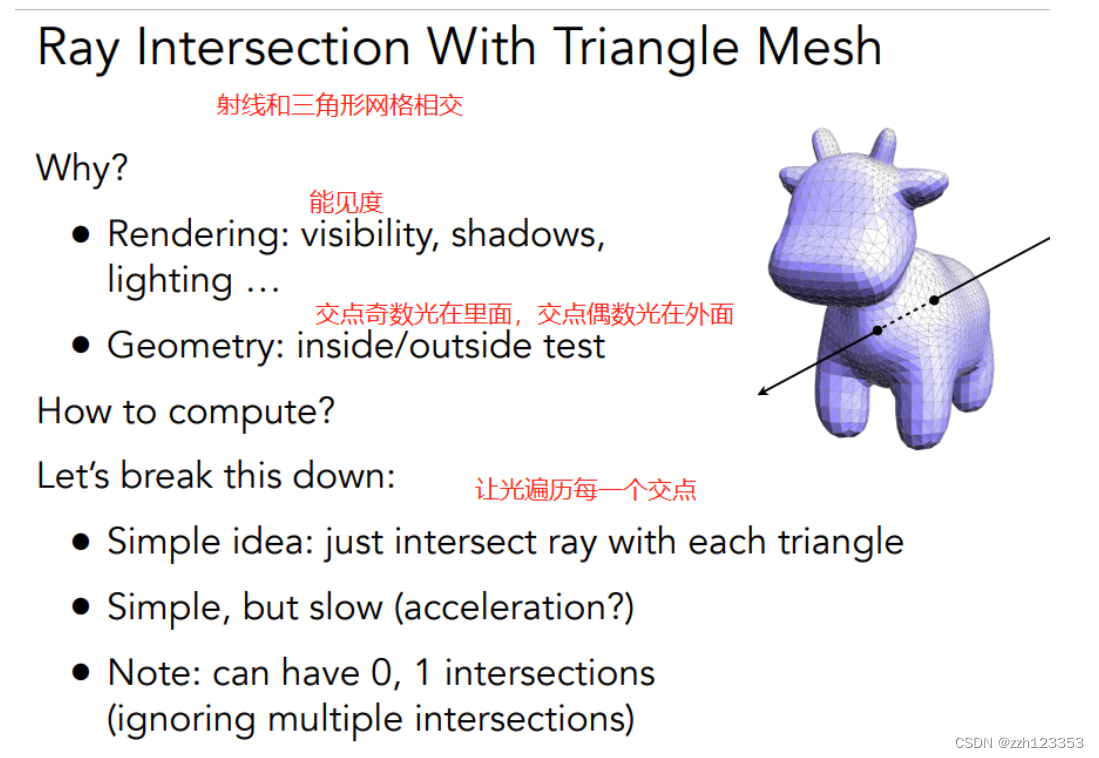
Ray Tracing
为什么使用ray tracing呢?
- 光栅化软阴影困难
- Glossy reflection光滑物体反射
- 光线弹射多次,间接光照
理论
- 光是直线传播
- 光线和光线不会发生碰撞(实际上并不是,假设)
- 光线从光源进入眼睛(也可以认为眼睛发出光线看到光源)(光路可逆性)
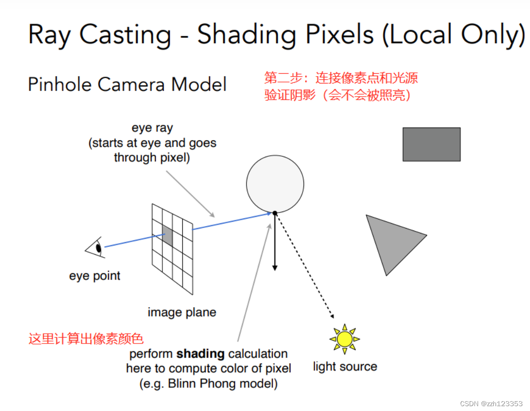
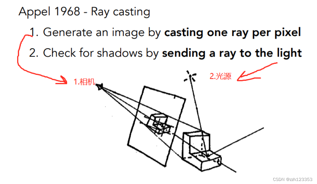 对每个像素:过摄像机 和 这个像素连起来
记录最近的交点(解决深度缓存问题)再通过这个点 和 光源 连线——判断这个点是否对光源可见(判断是不是在阴影里) 简单来说:
1.能不能看见(和camera连)
2.会不会被照亮(和光源连)

计算问题转化成为
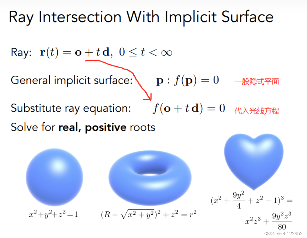
物体和光源求交点

 ## 光线与三角形面秋交点
 方法:
方法:
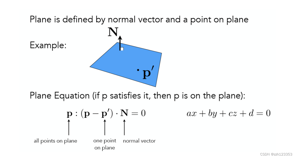 图中对于平面方程的讲解已经很清楚。那么到这里其实已经成功把对显示曲面的求交又转化为了类似隐式曲面求交的方法,对于任意一个三角面来说,它一定处于一个平面之上,只需求出光线与平面的交点,再判断该交点是否在三角形内,就可以得到光线是否与三角形面相交的结果了!
首先给出如何计算光线与平面交点的过程:
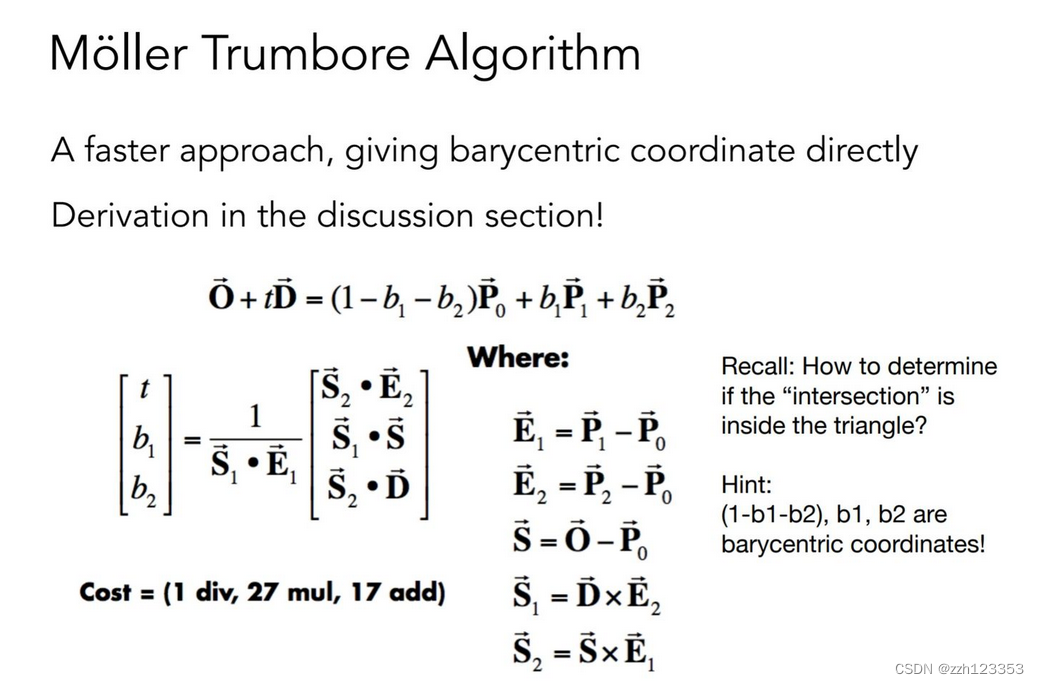
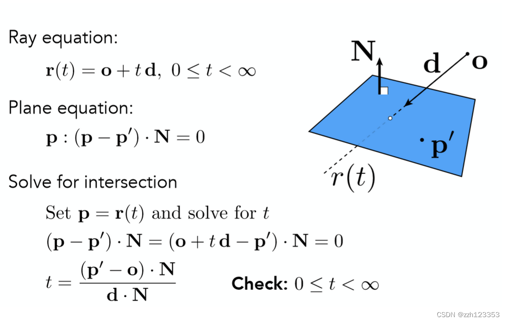 得到参数 t 之后,自然可以计算出交点,并且再去计算出重心坐标就能判断该交点是否在三角形内了,但是这种方法略显繁琐,能不能一步就得到结果呢?当然可以!
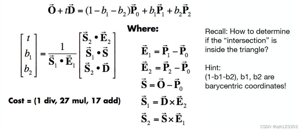 直接将点的形式用重心坐标的形式表示,随后利用克莱姆法则求解线性方程组即可!(推导过程省略,但其实就是用了线代知识里面的克莱姆法则。)
性能问题:对于复杂的场景不能用原始方法,比如几千万个面的场景
加速结构-BVH
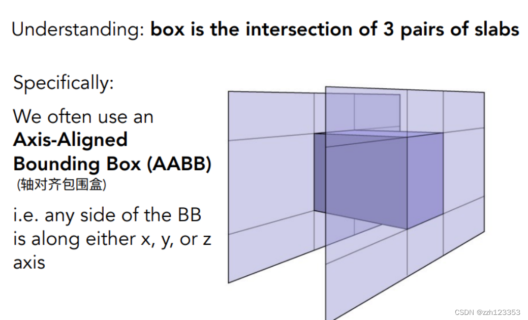 直接求光线与包围盒的交点:
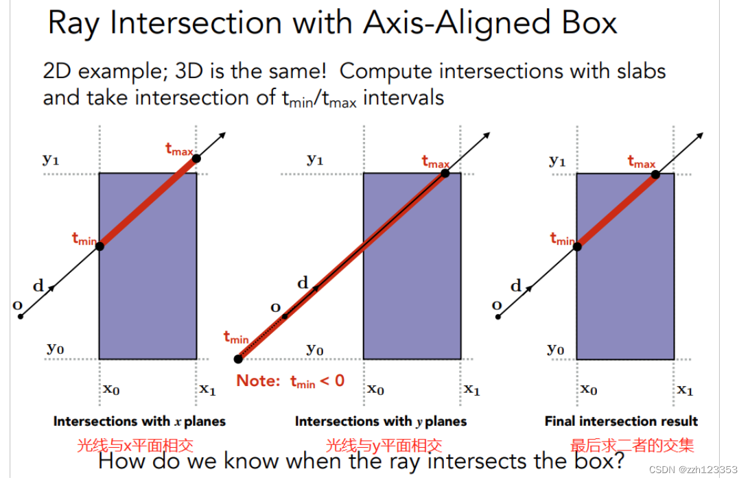
- 求出光线与一对x平面的交点,先进入的交点(偏小的那个)记为 tmin
- 后出去的交点(偏大的那个)记为 tmax,
- 紧接着如中间图所示计算出光线与y平面的两个交点同样记为另外一组tmin, tmax,
- 当然计算的过程中要注意如果任意的 t < 0,那么这代表的是光线反向传播与对应平面的交点。
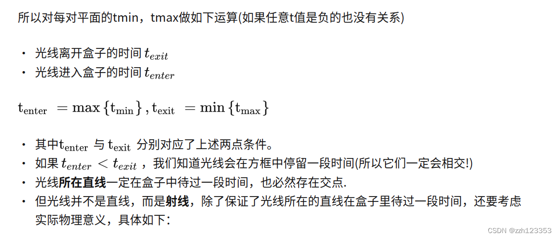
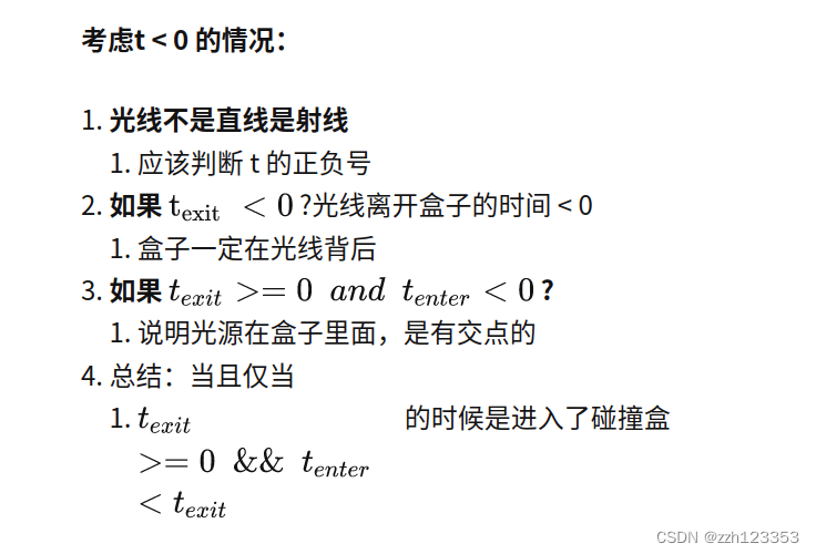
真正的交点:
1 只有当光线进入了 所有的平面 才算是真正进入了盒子中
2 只要当光线离开了 任意平面 就算是真正离开了盒子
Path Tracing
辐射度量学
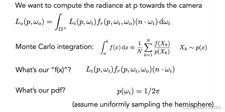
path tracing
光线追踪的一种,解决了Whitted-Style Ray Tracing的一些问题,例如
- 反射到镜面对应方向附近的一圈而并非单单镜面反射
- 漫反射不应该停下来
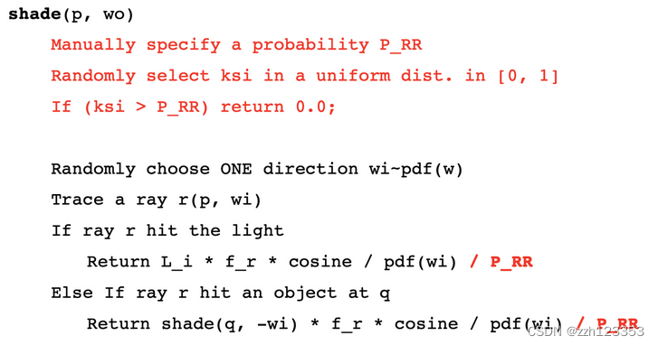
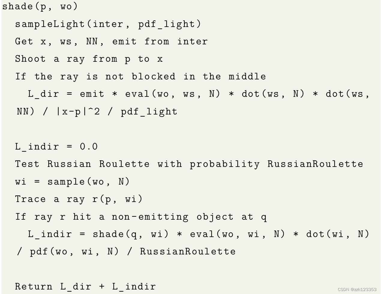
伪代码:
L
o
(
p
,
ω
o
)
=
∫
Ω
+
L
i
(
p
,
ω
i
)
f
r
(
p
,
ω
i
,
ω
o
)
(
n
⋅
ω
i
)
d
ω
i
≈
1
N
∑
i
=
1
N
L
i
(
p
,
ω
i
)
f
r
(
p
,
ω
i
,
ω
o
)
(
n
⋅
ω
i
)
p
(
ω
i
)
\begin{aligned} L_{o}\left(p, \omega_{o}\right) &=\int_{\Omega^{+}} L_{i}\left(p, \omega_{i}\right) f_{r}\left(p, \omega_{i}, \omega_{o}\right)\left(n \cdot \omega_{i}\right) \mathrm{d} \omega_{i} \\ & \approx \frac{1}{N} \sum_{i=1}^{N} \frac{L_{i}\left(p, \omega_{i}\right) f_{r}\left(p, \omega_{i}, \omega_{o}\right)\left(n \cdot \omega_{i}\right)}{p\left(\omega_{i}\right)} \end{aligned}
Lo(p,ωo)=∫Ω+Li(p,ωi)fr(p,ωi,ωo)(n⋅ωi)dωi≈N1i=1∑Np(ωi)Li(p,ωi)fr(p,ωi,ωo)(n⋅ωi)
问题:不高效,很多光线无功而返
解决:从光源出发采样,将公式匹配好即可
L o ( x , ω o ) = ∫ Ω + L i ( x , ω i ) f r ( x , ω i , ω o ) cos θ d ω i = ∫ A L i ( x , ω i ) f r ( x , ω i , ω o ) cos θ cos θ ′ ∥ x ′ − x ∥ 2 d A \begin{aligned} L_{o}\left(x, \omega_{o}\right) &=\int_{\Omega^{+}} L_{i}\left(x, \omega_{i}\right) f_{r}\left(x, \omega_{i}, \omega_{o}\right) \cos \theta \mathrm{d} \omega_{i} \\ &=\int_{A} L_{i}\left(x, \omega_{i}\right) f_{r}\left(x, \omega_{i}, \omega_{o}\right) \frac{\cos \theta \cos \theta^{\prime}}{\left\|x^{\prime}-x\right\|^{2}} \mathrm{d} A \end{aligned} Lo(x,ωo)=∫Ω+Li(x,ωi)fr(x,ωi,ωo)cosθdωi=∫ALi(x,ωi)fr(x,ωi,ωo)∥x′−x∥2cosθcosθ′dA
作业
作业0
配置环境,熟悉操作。
作业1
完成对MVP矩阵的求取
- Model Matrix
rotate + translation
Eigen::Matrix4f get_model_matrix(float rotation_angle)
{
    Eigen::Matrix4f model = Eigen::Matrix4f::Identity();

    model << cos(rotation_angle / 180.0 * M_PI), -sin(rotation_angle / 180.0 * M_PI), 0, 0,
        sin(rotation_angle / 180.0 * M_PI), cos(rotation_angle / 180.0 * M_PI), 0, 0,
        0, 0, 1, 0,
        0, 0, 0, 1;
    return model;
}
- View Matrix
这里面没有旋转,只考虑了平移
Eigen::Matrix4f get_view_matrix(Eigen::Vector3f eye_pos)
{
    Eigen::Matrix4f view = Eigen::Matrix4f::Identity();

    Eigen::Matrix4f translate;
    translate << 1, 0, 0, -eye_pos[0], 0, 1, 0, -eye_pos[1], 0, 0, 1,
        -eye_pos[2], 0, 0, 0, 1;

    view = translate * view;

    return view;
}
- Projection Matrix
这个是最重要的,投影矩阵,
透视投影矩阵可以看为先将视锥体进行挤压成一个长方体,再将长方体平移到中心并压缩到[-1, 1]^(3)的立方体中,这三步逐一完成。-
挤压的Matrix推导
定义三个原则:1.近平面的所有点坐标不变
2.远平面的所有点坐标z值不变 都是f
3.远平面的中心点坐标值不变 为(0,0,f)
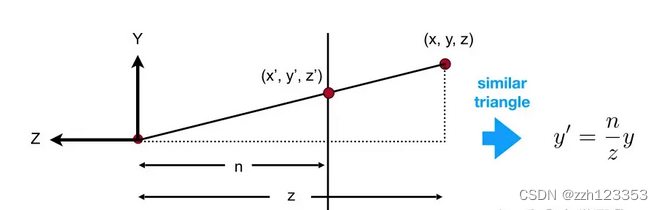
根据x,y,z相似三角形关系,可以推导出矩阵如下,注意n和z都表示的是坐标:
M = ( n 0 0 0 0 n 0 0 . . . . . . . . . . . . 0 0 1 0 ) M = \left( \begin{matrix} n & 0 & 0 & 0 \\ 0 & n & 0 & 0\\ ... &... &... & ... \\ 0 & 0 & 1 & 0 \\ \end{matrix} \right) M= n0...00n...000...100...0
第三行的推倒,可以根据近平面的点和远平面中心不发生变化列出两个方程,求解即可得到矩阵
M = ( n 0 0 0 0 n 0 0 0 0 n + f − n f 0 0 1 0 ) M = \left( \begin{matrix} n & 0 & 0 & 0 \\ 0 & n & 0 & 0\\ 0 &0 &n + f & -nf \\ 0 & 0 & 1 & 0 \\ \end{matrix} \right) M= n0000n0000n+f100−nf0 -
平移矩阵
长方体中心移动到原点位置
T = ( 1 0 0 − ( r + l ) / 2 0 1 0 − ( t + b ) / 2 0 0 1 − ( n + f ) / 2 0 0 0 1 ) T = \left( \begin{matrix} 1 & 0 & 0 & -(r + l) / 2\\ 0 & 1& 0 & -(t + b) / 2\\ 0 &0 & 1 & -(n + f) / 2 \\ 0 & 0 & 0 & 1 \\ \end{matrix} \right) T= 100001000010−(r+l)/2−(t+b)/2−(n+f)/21 -
缩放矩阵
S = ( 2 / ( r − l ) 0 0 0 0 2 / ( t − b ) 0 0 0 0 2 / ( n − f ) 0 0 0 0 1 ) S = \left( \begin{matrix} 2 /(r - l) & 0 & 0 & 0\\ 0 & 2 / (t - b)& 0 & 0\\ 0 &0 & 2 / (n - f) & 0 \\ 0 & 0 & 0 & 1 \\ \end{matrix} \right) S= 2/(r−l)00002/(t−b)00002/(n−f)00001
最终 P = S ∗ T ∗ M P = S * T * M P=S∗T∗M
-
实现:
Eigen::Matrix4f get_projection_matrix(float eye_fov, float aspect_ratio,
                                      float zNear, float zFar)
{

    //传入的是距离
    //经过view变换后,摄像机在0 0 0的位置,往z轴负方向上观看
    zNear = -zNear;
    zFar = -zFar;
    // Students will implement this function
    Eigen::Matrix4f projection = Eigen::Matrix4f::Identity();
    Eigen::Matrix4f p, t, o;
    p << zNear, 0, 0, 0,
        0, zNear, 0, 0,
        0, 0, zNear + zFar, -zNear * zFar,
        0, 0, 1, 0;

    //求取zNear空间的锥体范围
    float top = std::abs(zNear) * std::tan(0.5 * eye_fov / 180.0f * M_PI);
    float bottom = -top;

    float left = -top * aspect_ratio;
    float right = -left;
    t << 1, 0, 0, -(left + right) / 2,
        0, 1, 0, -(top + bottom) / 2,
        0, 0, 1, -(zFar + zFar) / 2,
        0, 0, 0, 1;
    o << 2 / (right - left), 0, 0, 0,
        0, 2 / (top - bottom), 0, 0,
        0, 0, 2 / (zFar - zNear), 0,
        0, 0, 0, 1;

    projection = o * t * p;

    // TODO: Implement this function
    // Create the projection matrix for the given parameters.
    // Then return it.
    return projection;
}
作业2
画出两个交叠的三角形,实现三角形栅格化算法
思路:
首先确定三角的包围盒,即x y方向的最值,形成一个长方形区域,遍历长方形区域的每一个点,判断是否在三角形内,利用叉乘来判断,叉乘符号相同则在三角形平面内
//                  C
//                  *
//                 * *
//                * P *
//              A*******B
static bool insideTriangle(float x, float y, const Vector3f* v)
{
    // TODO : Implement this function to check if the point (x, y) is inside the triangle represented by _v[0], _v[1], _v[2]

    float x_mid = x;
    float y_mid = y;
    Eigen::Vector2f ap(x_mid - v[0].x(), y_mid - v[0].y());
    Eigen::Vector2f ab(v[1].x() - v[0].x(), v[1].y() - v[0].y());

    Eigen::Vector2f bp(x_mid - v[1].x(), y_mid - v[1].y());
    Eigen::Vector2f bc(v[2].x() - v[1].x(), v[2].y() - v[1].y());

    Eigen::Vector2f cp(x_mid - v[2].x(), y_mid - v[2].y());
    Eigen::Vector2f ca(v[0].x() - v[2].x(), v[0].y() - v[2].y());

    if(ap[0] * ab[1] - ab[0] * ap[1] <= 0 &&
       bp[0] * bc[1] - bc[0] * bp[1] <= 0 &&
       cp[0] * ca[1] - ca[0] * cp[1] <= 0)
        return true;

    return false;
}
然后利用插值求出空间中的z值,利用zbufer来比较决定改点显示的颜色
注意:这里面zbuffer初始化为极大值,z都被转化了正值,z值越小,表示离摄像机越近,就会被显示
static std::tuple<float, float, float> computeBarycentric2D(float x, float y, const Vector3f* v)
{
    float c1 = (x*(v[1].y() - v[2].y()) + (v[2].x() - v[1].x())*y + v[1].x()*v[2].y() - v[2].x()*v[1].y()) / (v[0].x()*(v[1].y() - v[2].y()) + (v[2].x() - v[1].x())*v[0].y() + v[1].x()*v[2].y() - v[2].x()*v[1].y());
    float c2 = (x*(v[2].y() - v[0].y()) + (v[0].x() - v[2].x())*y + v[2].x()*v[0].y() - v[0].x()*v[2].y()) / (v[1].x()*(v[2].y() - v[0].y()) + (v[0].x() - v[2].x())*v[1].y() + v[2].x()*v[0].y() - v[0].x()*v[2].y());
    float c3 = (x*(v[0].y() - v[1].y()) + (v[1].x() - v[0].x())*y + v[0].x()*v[1].y() - v[1].x()*v[0].y()) / (v[2].x()*(v[0].y() - v[1].y()) + (v[1].x() - v[0].x())*v[2].y() + v[0].x()*v[1].y() - v[1].x()*v[0].y());
    return {c1,c2,c3};
}

void rst::rasterizer::rasterize_triangle(const Triangle& t) {
    auto v = t.toVector4();

    int left = std::min({t.v[0].x(), t.v[1].x(), t.v[2].x()});
    int right = std::max({t.v[0].x(), t.v[1].x(), t.v[2].x()});
    int top = std::max({t.v[0].y(), t.v[1].y(), t.v[2].y()});
    int bottom = std::min({t.v[0].y(), t.v[1].y(), t.v[2].y()});


    for(int i = left; i <= right; ++i){
        for(int j = bottom; j <= top; ++j){
            if(insideTriangle(i + 0.5f, j + 0.5f, t.v)){
                auto[alpha, beta, gamma] = computeBarycentric2D(i, j, t.v);
                float w_reciprocal = 1.0/(alpha / v[0].w() + beta / v[1].w() + gamma / v[2].w());
                float z_interpolated = alpha * v[0].z() / v[0].w() + beta * v[1].z() / v[1].w() + gamma * v[2].z() / v[2].w();
                z_interpolated *= w_reciprocal;
                if(z_interpolated < depth_buf[get_index(i, j)]){
                    depth_buf[get_index(i, j)] = z_interpolated;
                    set_pixel(Eigen::Vector3f(i, j, z_interpolated), t.getColor());
                }
            }
        }
    }
}
提升:MSAA
将一个像素点切分为四块,分别遍历四块位置是否在三角形内,更新zbuffer和color buffer。
这里面zbuffer和color buffer大小都为原来的4倍。
可以看到比上面多了一个颜色缓冲区,之前可见后,直接将该点位置设置成一定的color。现在要将每一个颜色都存储起来,最终计算该点的颜色和深度,存入对应位置。
    auto v = t.toVector4();

    int left = std::min({t.v[0].x(), t.v[1].x(), t.v[2].x()});
    int right = std::max({t.v[0].x(), t.v[1].x(), t.v[2].x()});
    int top = std::max({t.v[0].y(), t.v[1].y(), t.v[2].y()});
    int bottom = std::min({t.v[0].y(), t.v[1].y(), t.v[2].y()});
    std::vector<Eigen::Vector2f > step{
        {0.25, 0.25}, {0.25, 0.75},
        {0.75, 0.25}, {0.75, 0.75}
    };

    for(int i = left; i <= right; ++i){
        for(int j = bottom; j <= top; ++j){
            int count = 0;
            float minDepth = 1000;
            for(int k = 0; k < 4; ++k){
                if(insideTriangle(i + step[k][0], j + step[k][1], t.v)){
                    auto[alpha, beta, gamma] = computeBarycentric2D(i + step[k][0], j + step[k][1], t.v);
                    float w_reciprocal = 1.0/(alpha / v[0].w() + beta / v[1].w() + gamma / v[2].w());
                    float z_interpolated = alpha * v[0].z() / v[0].w() + beta * v[1].z() / v[1].w() + gamma * v[2].z() / v[2].w();
                    z_interpolated *= w_reciprocal;
                    if(z_interpolated < super_depth_buf[get_index(i, j) * 4 + k]){
                        ++count;
                        super_depth_buf[get_index(i, j) * 4 + k] = z_interpolated;
                        super_frame_buf[get_index(i, j) * 4 + k] = t.getColor();
                        minDepth = std::min(minDepth, super_depth_buf[get_index(i, j) * 4 + k]);
                    }
                }
            }
            if(count > 0){
                Eigen::Vector3f color = (super_frame_buf[get_index(i, j) * 4] +  super_frame_buf[get_index(i, j) * 4 + 1]
                    + super_frame_buf[get_index(i, j) * 4 + 2] + super_frame_buf[get_index(i, j) * 4 + 3]) / 4.0f;
                set_pixel(Vector3f(i, j, minDepth), color);
                depth_buf[get_index(i, j)] = minDepth;
            }
        }
    }
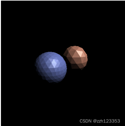
作业3
实现Blinn-Phong shader、normal shader、bump shader、displce shader等等
- 插值
首先关于插值,在作业二中,我们插值了z深度,在这里要对法线、纹理坐标、颜色、着色点进行插值,
前面计算将顶点坐标转换到了view space,在view空间下进行计算进行着色
//Screen space rasterization
void rst::rasterizer::rasterize_triangle(const Triangle& t, const std::array<Eigen::Vector3f, 3>& view_pos)
{

    auto v = t.toVector4();
    auto& normal = t.normal;
    auto& color = t.color;
    auto& coords = t.tex_coords;

    int left = std::min({t.v[0].x(), t.v[1].x(), t.v[2].x()});
    int right = std::max({t.v[0].x(), t.v[1].x(), t.v[2].x()});
    int top = std::max({t.v[0].y(), t.v[1].y(), t.v[2].y()});
    int bottom = std::min({t.v[0].y(), t.v[1].y(), t.v[2].y()});


    for(int i = left; i <= right; ++i){
        for(int j = bottom; j <= top; ++j){
            if(insideTriangle(i + 0.5f, j + 0.5f, t.v)){
                auto [alpha, beta, gamma] = computeBarycentric2D(i, j, t.v);
                float w_reciprocal = 1.0/(alpha / v[0].w() + beta / v[1].w() + gamma / v[2].w());
                float z_interpolated = alpha * v[0].z() / v[0].w() + beta * v[1].z() / v[1].w() + gamma * v[2].z() / v[2].w();
                z_interpolated *= w_reciprocal;

                if(z_interpolated < depth_buf[get_index(i, j)]){
                    depth_buf[get_index(i, j)] = z_interpolated;

                    //有写好的api
                    Eigen::Vector3f interpolated_normal = interpolate(alpha, beta, gamma, normal[0], normal[1], normal[2], 1);
                    Eigen::Vector3f interpolated_color = interpolate(alpha, beta, gamma, color[0], color[1], color[2], 1);
                    Eigen::Vector3f interpolated_shadingcoords = interpolate(alpha, beta, gamma, view_pos[0], view_pos[1], view_pos[2], 1);
                    Eigen::Vector2f interpolated_texcoords = interpolate(alpha, beta, gamma, coords[0], coords[1], coords[2], 1);

                    fragment_shader_payload payload( interpolated_color, interpolated_normal.normalized(), interpolated_texcoords, texture ? &*texture : nullptr);
                    payload.view_pos = interpolated_shadingcoords;
                    //Instead of passing the triangle's color directly to the frame buffer, pass the color to the shaders first to get the final color;
                    Eigen::Vector3f pixel_color = fragment_shader(payload);
                    set_pixel(Eigen::Vector2i(i, j), Eigen::Vector3f(pixel_color));
                }
            }
        }
    }
}
- Blinn-Phong shader
三项相加 L = 环境光 + 漫反射 + 高光反射 L = 环境光+ 漫反射+高光反射 L=环境光+漫反射+高光反射
这里面计算viewDir和lightDir的时候,因为之前说了是在View space下,所以viewDir = -viewPos,看了很多其他人写的,这里是eye_pos - viewPos,不是很理解;没有说lightPos是在哪个空间下的坐标,这里默认就当是在view Space下了。
Eigen::Vector3f phong_fragment_shader(const fragment_shader_payload& payload)
{
    Eigen::Vector3f ka = Eigen::Vector3f(0.005, 0.005, 0.005); //环境光系数
    Eigen::Vector3f kd = payload.color; //漫反射系数
    Eigen::Vector3f ks = Eigen::Vector3f(0.7937, 0.7937, 0.7937); //高光系数

    auto l1 = light{{20, 20, 20}, {500, 500, 500}};
    auto l2 = light{{-20, 20, 0}, {500, 500, 500}};

    std::vector<light> lights = {l1, l2};
    Eigen::Vector3f amb_light_intensity{10, 10, 10};
    Eigen::Vector3f eye_pos{0, 0, 10};

    float p = 150;

    Eigen::Vector3f color = payload.color;
    Eigen::Vector3f point = payload.view_pos;
    Eigen::Vector3f normal = payload.normal.normalized();

    Eigen::Vector3f result_color = {0, 0, 0};


    for (auto& light : lights)
    {
        auto viewLightPos = light.position; ///- eye_pos;

        Eigen::Vector3f lightDir = (viewLightPos - payload.view_pos).normalized() ;
        Eigen::Vector3f viewDir = (-payload.view_pos).normalized();
        //ambient
        Eigen::Vector3f ambient = ka.cwiseProduct(amb_light_intensity);
        //difuse
        float r2 = (viewLightPos - point).dot(viewLightPos- point);
        Eigen::Vector3f diffuse = kd.cwiseProduct(light.intensity / r2) * std::max(0.0f, lightDir.dot(normal));
		//specular
        auto halfVector = (lightDir + viewDir).normalized();
        auto specular = ks.cwiseProduct(light.intensity / r2) * std::pow(std::max(0.0f, halfVector.dot(normal)), p);

        result_color += ambient + diffuse + specular;
    }
    return result_color * 255.f;
}
- bump shader
接着是凹凸贴图的应用,核心就是查表求法向量,通过更改对应点的法向量来得到凹凸的反射效果:
Eigen::Vector3f bump_fragment_shader(const fragment_shader_payload& payload)
{

    Eigen::Vector3f ka = Eigen::Vector3f(0.005, 0.005, 0.005);
    Eigen::Vector3f kd = payload.color;
    Eigen::Vector3f ks = Eigen::Vector3f(0.7937, 0.7937, 0.7937);

    auto l1 = light{{20, 20, 20}, {500, 500, 500}};
    auto l2 = light{{-20, 20, 0}, {500, 500, 500}};

    std::vector<light> lights = {l1, l2};
    Eigen::Vector3f amb_light_intensity{10, 10, 10};
    Eigen::Vector3f eye_pos{0, 0, 10};

    float p = 150;

    Eigen::Vector3f color = payload.color;
    Eigen::Vector3f point = payload.view_pos;
    Eigen::Vector3f normal = payload.normal;


    float kh = 0.2, kn = 0.1;


    Eigen::Vector3f n = normal;
    float x = n.x();
    float y = n.y();
    float z = n.z();

    Eigen::Vector3f t(x*y/sqrt(x*x+z*z),sqrt(x*x+z*z),z*y/sqrt(x*x+z*z));
    Eigen::Vector3f b = n.cross(t);

    Eigen::Matrix3f TBN;
    TBN.col(0) = t;
    TBN.col(1) = b;
    TBN.col(2) = n;

    int w = payload.texture->width;
    int h = payload.texture->height;
    float u = payload.tex_coords.x();
    float v = payload.tex_coords.y();

    auto huv = payload.texture->getColor(u,v).norm();
    float dU = kh * kn * (payload.texture->getColor(u+1.0f/w,v).norm()-huv);
    float dV = kh * kn * (payload.texture->getColor(u,v+1.0f/h).norm()-huv);

    Eigen::Vector3f ln(-dU, -dV, 1.f);
    normal = (TBN * ln).normalized();

    Eigen::Vector3f result_color = {0, 0, 0};
    result_color = normal;

    return result_color * 255.f;
}
- dispace shader
移贴图基本沿用凹凸贴图的代码就行,关键是在于位移贴图改变了原本点的位置并考虑了光线的因素,我们只需要复制先前BP模型中的光线部分,并且写上关键代码:point +=(kn * normal * payload.texture->getColor(u, v).norm()),即可完成此部分内容。
Eigen::Vector3f displacement_fragment_shader(const fragment_shader_payload& payload)
{

    Eigen::Vector3f ka = Eigen::Vector3f(0.005, 0.005, 0.005);
    Eigen::Vector3f kd = payload.color;
    Eigen::Vector3f ks = Eigen::Vector3f(0.7937, 0.7937, 0.7937);

    auto l1 = light{{20, 20, 20}, {500, 500, 500}};
    auto l2 = light{{-20, 20, 0}, {500, 500, 500}};

    std::vector<light> lights = {l1, l2};
    Eigen::Vector3f amb_light_intensity{10, 10, 10};
    Eigen::Vector3f eye_pos{0, 0, 10};

    float p = 150;

    Eigen::Vector3f color = payload.color;
    Eigen::Vector3f point = payload.view_pos;
    Eigen::Vector3f normal = payload.normal;

    float kh = 0.2, kn = 0.1;

    float x = normal.x();
    float y = normal.y();
    float z = normal.z();

    Eigen::Vector3f t(x*y/sqrt(x*x+z*z),sqrt(x*x+z*z),z*y/sqrt(x*x+z*z));
    Eigen::Vector3f b = normal.cross(t);

    Eigen::Matrix3f TBN;
    TBN.col(0) = t;
    TBN.col(1) = b;
    TBN.col(2) = normal;

    int w = payload.texture->width;
    int h = payload.texture->height;
    float u = payload.tex_coords.x();
    float v = payload.tex_coords.y();

    auto huv = payload.texture->getColor(u,v).norm();
    float dU = kh * kn * (payload.texture->getColor(u+1.0f/w,v).norm()-huv);
    float dV = kh * kn * (payload.texture->getColor(u,v+1.0f/h).norm()-huv);

    Eigen::Vector3f ln(-dU, -dV, 1.f);
    point = point + normal * kn * huv;
    normal = (TBN * ln).normalized();


    Eigen::Vector3f result_color = {0, 0, 0};

    for (auto& light : lights)
    {
        auto viewLightPos = light.position; ///- eye_pos;

        Eigen::Vector3f lightDir = (viewLightPos - point).normalized() ;
        Eigen::Vector3f viewDir = (-point).normalized();

        //ambient
        Eigen::Vector3f ambient = ka.cwiseProduct(amb_light_intensity);

        //difuse
        float r2 = (viewLightPos - point).dot(viewLightPos- point);
        Eigen::Vector3f diffuse = kd.cwiseProduct(light.intensity / r2) * std::max(0.0f, lightDir.dot(normal));
		//specular
        auto halfVector = (lightDir + viewDir).normalized();
        auto specular = ks.cwiseProduct(light.intensity / r2) * std::pow(std::max(0.0f, halfVector.dot(normal)), p);

        result_color += ambient + diffuse + specular;
    }
    return result_color * 255.f;
}
作业4
递归实现贝塞尔曲线的绘制
方法一:native
直接根据根据数学公式直接计算
void naive_bezier(const std::vector<cv::Point2f> &points, cv::Mat &window)
{
    auto &p_0 = points[0];
    auto &p_1 = points[1];
    auto &p_2 = points[2];
    auto &p_3 = points[3];

    for (double t = 0.0; t <= 1.0; t += 0.001)
    {
        auto point = std::pow(1 - t, 3) * p_0 + 3 * t * std::pow(1 - t, 2) * p_1 +
                 3 * std::pow(t, 2) * (1 - t) * p_2 + std::pow(t, 3) * p_3;

        window.at<cv::Vec3b>(point.y, point.x)[2] = 255;
    }
}
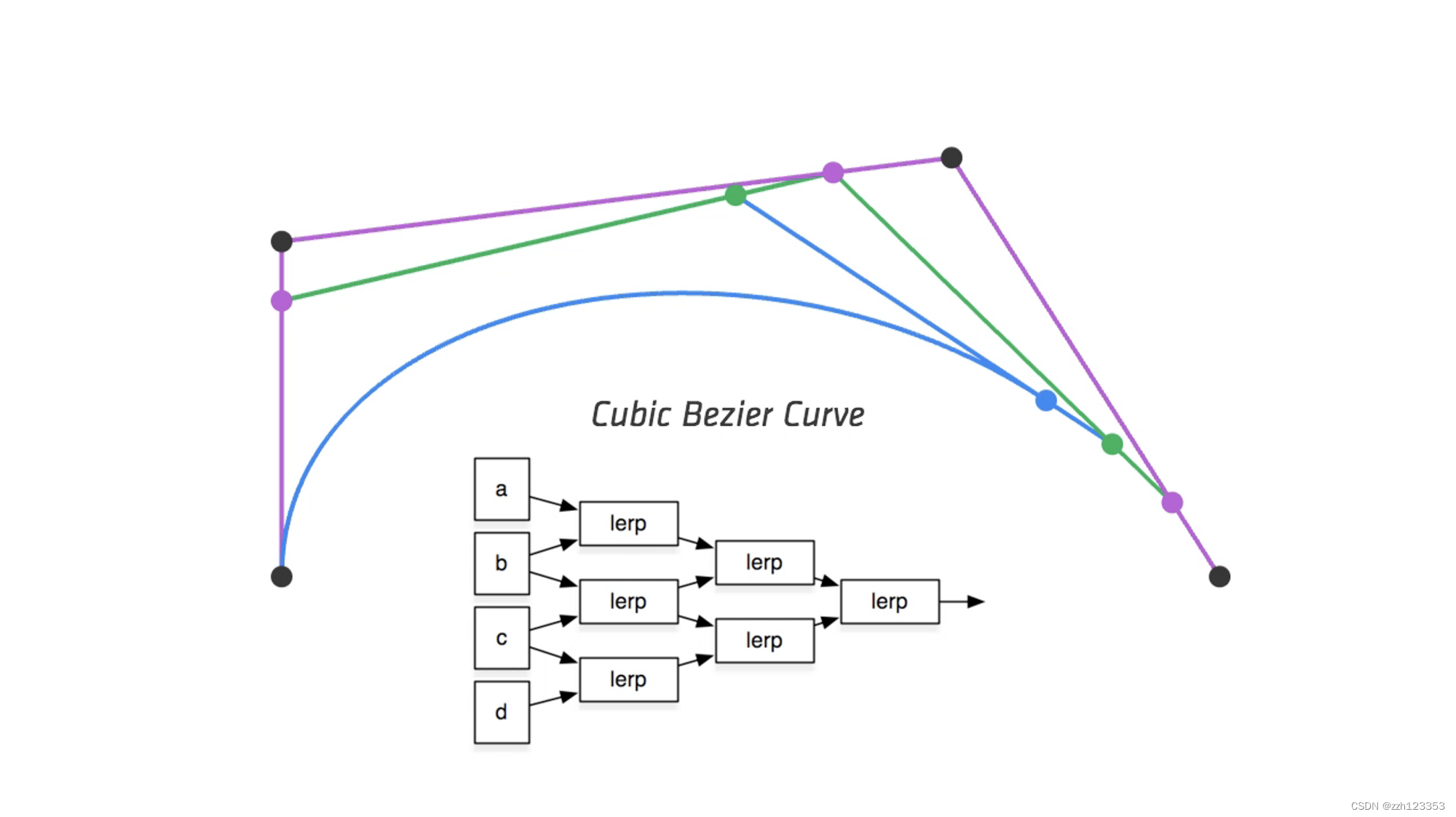
方法二:递归
终止条件:当控制点只剩一个
递归过程:计算i个点经过插值形成的i - 1个点,递归
cv::Point2f lerp_point(const cv::Point2f& p1, const cv::Point2f& p2, float t){
    return t * p2 + (1 - t) * p1;
}

cv::Point2f recursive_bezier(const std::vector<cv::Point2f> &control_points, float t)
{
    // TODO: Implement de Casteljau's algorithm
    if(control_points.size() == 1){
        return control_points[0];
    }

    std::vector<cv::Point2f> lerp_points;
    for(int i = 0; i < control_points.size() - 1; ++i){
        lerp_points.push_back(lerp_point(control_points[i], control_points[i + 1], t));
    }
    return recursive_bezier(lerp_points, t);
}

void bezier(const std::vector<cv::Point2f> &control_points, cv::Mat &window)
{
    // TODO: Iterate through all t = 0 to t = 1 with small steps, and call de Casteljau's
    // recursive Bezier algorithm.

    for(float t = 0.0f; t <=1.0f; t += 0.001){
        cv::Point2f point = recursive_bezier(control_points, t);
        window.at<cv::Vec3b>(point.y, point.x)[1] = 255;
    }
}
作业5
RayTacing
作业里面主要是实现从屏幕发射光线以及光线和三角形求交点。
首先来梳理一下光线追踪的框架
- main
主函数中创建了场景,添加了光源、物体,并设置了物体的属性等,然后调用render - Render
在render中创建了颜色缓冲区,不需要深度缓冲,因为在发射光线与物体求交的时候,我们选取的是最先被击中的物体,
接下来看看如何实现从屏幕发射光线到三维世界,前面所学,物体->MVP->view port->screen space,最终输出到屏幕空间,现在反过来即可:
void Renderer::Render(const Scene& scene)
{
    std::vector<Vector3f> framebuffer(scene.width * scene.height);

    float scale = std::tan(deg2rad(scene.fov * 0.5f));
    float imageAspectRatio = scene.width / (float)scene.height;

    // Use this variable as the eye position to start your rays.
    Vector3f eye_pos(0);
    int m = 0;
    for (int j = 0; j < scene.height; ++j)
    {
        for (int i = 0; i < scene.width; ++i)
        {
            // generate primary ray direction

            //concert screen space -> NDC
            float ndc_x = (i + 0.5) * 2 / (scene.width - 1) - 1;
            float ndc_y = (j + 0.5) * 2 / (scene.height - 1) - 1;

            //ndc space -> world space

            float world_x = ndc_x * scale * imageAspectRatio;
            float world_y = -ndc_y * scale;


            float x = world_x;
            float y = world_y;

            // TODO: Find the x and y positions of the current pixel to get the direction
            // vector that passes through it.
            // Also, don't forget to multiply both of them with the variable *scale*, and
            // x (horizontal) variable with the *imageAspectRatio*

            Vector3f dir = Vector3f(x, y, -1); // Don't forget to normalize this direction!
            dir = normalize(dir);
            framebuffer[m++] = castRay(eye_pos, dir, scene, 0);
        }
        UpdateProgress(j / (float)scene.height);
    }

    // save framebuffer to file
    FILE* fp = fopen("binary.ppm", "wb");
    (void)fprintf(fp, "P6\n%d %d\n255\n", scene.width, scene.height);
    for (auto i = 0; i < scene.height * scene.width; ++i) {
        static unsigned char color[3];
        color[0] = (char)(255 * clamp(0, 1, framebuffer[i].x));
        color[1] = (char)(255 * clamp(0, 1, framebuffer[i].y));
        color[2] = (char)(255 * clamp(0, 1, framebuffer[i].z));
        fwrite(color, 1, 3, fp);
    }
    fclose(fp);
}
主要看castRay函数,递归出口,depth满足最大递归次数,将发射的光线与场景物体进行求交点,取最近的交点,并根据材质的类型进行相应的递归,并在漫反射物体处判断阴影并停止递归,求取阴影的时候,从漫反射点向光源发射一条射线,并判断是否会和中间的物体进相交,如果相交说明有物体挡在了它前面,产生阴影
Vector3f castRay(
        const Vector3f &orig, const Vector3f &dir, const Scene& scene,
        int depth)
{
    if (depth > scene.maxDepth) {
        return Vector3f(0.0,0.0,0.0);
    }

    Vector3f hitColor = scene.backgroundColor;
    if (auto payload = trace(orig, dir, scene.get_objects()); payload)
    {
        Vector3f hitPoint = orig + dir * payload->tNear;
        Vector3f N; // normal
        Vector2f st; // st coordinates
        payload->hit_obj->getSurfaceProperties(hitPoint, dir, payload->index, payload->uv, N, st);
        switch (payload->hit_obj->materialType) {
            case REFLECTION_AND_REFRACTION:
            {
                Vector3f reflectionDirection = normalize(reflect(dir, N));
                Vector3f refractionDirection = normalize(refract(dir, N, payload->hit_obj->ior));
                Vector3f reflectionRayOrig = (dotProduct(reflectionDirection, N) < 0) ?
                                             hitPoint - N * scene.epsilon :
                                             hitPoint + N * scene.epsilon;
                Vector3f refractionRayOrig = (dotProduct(refractionDirection, N) < 0) ?
                                             hitPoint - N * scene.epsilon :
                                             hitPoint + N * scene.epsilon;
                Vector3f reflectionColor = castRay(reflectionRayOrig, reflectionDirection, scene, depth + 1);
                Vector3f refractionColor = castRay(refractionRayOrig, refractionDirection, scene, depth + 1);
                float kr = fresnel(dir, N, payload->hit_obj->ior);
                hitColor = reflectionColor * kr + refractionColor * (1 - kr);
                break;
            }
            case REFLECTION:
            {
                float kr = fresnel(dir, N, payload->hit_obj->ior);
                Vector3f reflectionDirection = reflect(dir, N);
                Vector3f reflectionRayOrig = (dotProduct(reflectionDirection, N) < 0) ?
                                             hitPoint + N * scene.epsilon :
                                             hitPoint - N * scene.epsilon;
                hitColor = castRay(reflectionRayOrig, reflectionDirection, scene, depth + 1) * kr;
                break;
            }
            default:
            {
                // [comment]
                // We use the Phong illumation model int the default case. The phong model
                // is composed of a diffuse and a specular reflection component.
                // [/comment]
                Vector3f lightAmt = 0, specularColor = 0;
                Vector3f shadowPointOrig = (dotProduct(dir, N) < 0) ?
                                           hitPoint + N * scene.epsilon :
                                           hitPoint - N * scene.epsilon;
                // [comment]
                // Loop over all lights in the scene and sum their contribution up
                // We also apply the lambert cosine law
                // [/comment]
                for (auto& light : scene.get_lights()) {
                    Vector3f lightDir = light->position - hitPoint;
                    // square of the distance between hitPoint and the light
                    float lightDistance2 = dotProduct(lightDir, lightDir);
                    lightDir = normalize(lightDir);
                    float LdotN = std::max(0.f, dotProduct(lightDir, N));
                    // is the point in shadow, and is the nearest occluding object closer to the object than the light itself?
                    auto shadow_res = trace(shadowPointOrig, lightDir, scene.get_objects());
                    bool inShadow = shadow_res && (shadow_res->tNear * shadow_res->tNear < lightDistance2);

                    lightAmt += inShadow ? 0 : light->intensity * LdotN;
                    Vector3f reflectionDirection = reflect(-lightDir, N);

                    specularColor += powf(std::max(0.f, -dotProduct(reflectionDirection, dir)),
                        payload->hit_obj->specularExponent) * light->intensity;
                }
                hitColor = lightAmt * payload->hit_obj->evalDiffuseColor(st) * payload->hit_obj->Kd + specularColor * payload->hit_obj->Ks;
                break;
            }
        }
    }

    return hitColor;
}
与三角形求交点:直接带入公式:
bool rayTriangleIntersect(const Vector3f& v0, const Vector3f& v1, const Vector3f& v2, const Vector3f& orig,
                          const Vector3f& dir, float& tnear, float& u, float& v)
{
    // TODO: Implement this function that tests whether the triangle
    // that's specified bt v0, v1 and v2 intersects with the ray (whose
    // origin is *orig* and direction is *dir*)
    // Also don't forget to update tnear, u and v.
    Vector3f E1 = v1 - v0;
    Vector3f E2 = v2 - v0;
    Vector3f s = orig - v0;
    Vector3f s1 = crossProduct(dir, E2);
    Vector3f s2 = crossProduct(s, E1);

    float s1e1 = 1.0f / dotProduct(s1, E1);

    tnear = s1e1 * dotProduct(s2, E2);

    u = s1e1 * dotProduct(s1, s);
    v = s1e1 * dotProduct(s2, dir);

    if(tnear >= 0 && u >= 0 && v >= 0 && (1 - u - v) >= 0)
        return true;
    return false;
}
里面还有一些,反射、折射、菲涅尔折射求取的函数,学习以下:
- 反射
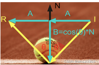
I = A + B R = A − B B = c o s ( θ ) ∗ N A = I − B I = A + B \\ R= A - B \\ B = cos(\theta) * N \\A = I-B I=A+BR=A−BB=cos(θ)∗NA=I−B
由此可以得出:
R = I − 2 ( N ∗ I ) ∗ N R = I - 2(N* I)*N R=I−2(N∗I)∗N
// Compute reflection direction
Vector3f reflect(const Vector3f &I, const Vector3f &N)
{
    return I - 2 * dotProduct(I, N) * N;
}
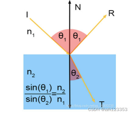
- 折射
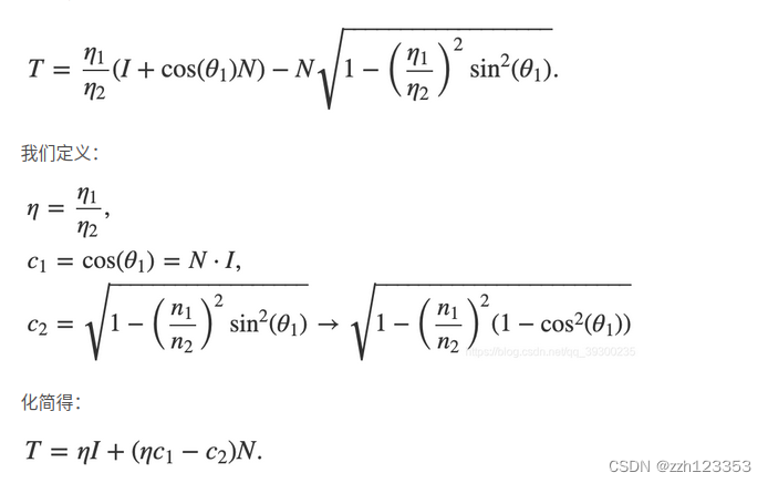
Vector3f refract(const Vector3f &I, const Vector3f &N, const float &ior)
{
    float cosi = clamp(-1, 1, dotProduct(I, N));
    float etai = 1, etat = ior;
    Vector3f n = N;
    if (cosi < 0) { cosi = -cosi; } else { std::swap(etai, etat); n= -N; }
    float eta = etai / etat;
    float k = 1 - eta * eta * (1 - cosi * cosi);
    return k < 0 ? 0 : eta * I + (eta * cosi - sqrtf(k)) * n;
}
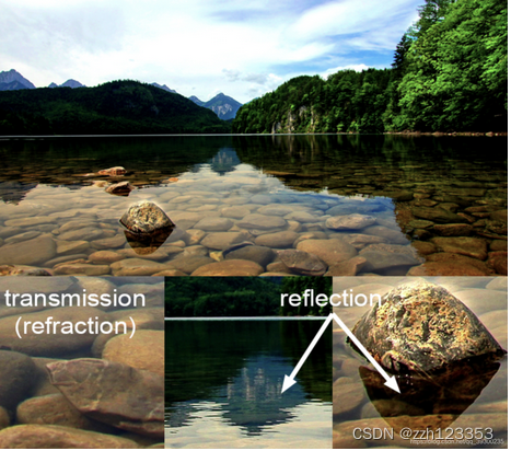
- 菲涅尔反射
透明物体(例如玻璃或水)既折射又反射。它们反射的光量与透射的光量实际上取决于入射角。当入射角减小时,透射的光量增加。并且由于按照能量守恒定律,反射光量加上折射光量必须等于入射光总量(不考虑光损失),因此可以推断出,入射角增大时,反射光量会增加,角度接近90度时最高可达100%。从技术上讲,玻璃球的边缘是100%反射的。但是在球体的中心,该球体仅反射约6%的入射光。我们可以看一幅图
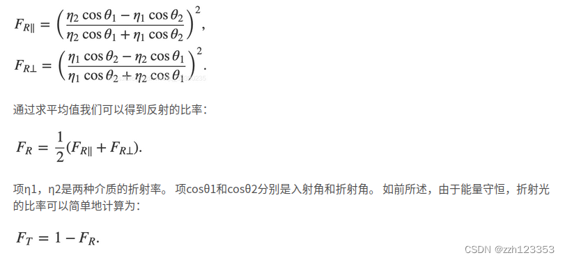
float fresnel(const Vector3f &I, const Vector3f &N, const float &ior)
{
    float cosi = clamp(-1, 1, dotProduct(I, N));
    float etai = 1, etat = ior;
    if (cosi > 0) {  std::swap(etai, etat); }
    // Compute sini using Snell's law
    float sint = etai / etat * sqrtf(std::max(0.f, 1 - cosi * cosi));
    // Total internal reflection
    if (sint >= 1) {
        return 1;
    }
    else {
        float cost = sqrtf(std::max(0.f, 1 - sint * sint));
        cosi = fabsf(cosi);
        float Rs = ((etat * cosi) - (etai * cost)) / ((etat * cosi) + (etai * cost));
        float Rp = ((etai * cosi) - (etat * cost)) / ((etai * cosi) + (etat * cost));
        return (Rs * Rs + Rp * Rp) / 2;
    }
    // As a consequence of the conservation of energy, transmittance is given by:
    // kt = 1 - kr;
}
作业6
基于作业5的rayTracingBVH加速结构,首先来整理一下给的作业的框架结构,设置主场景,读取bunny.obj兔子模型,创建MeshTriangle,在创建的时候,会在MeshTriangle内建立一个属于这个物体的BVH,然后将物体、光源添加到场景中,建立场景的BVH,建盒的过程,按照最大纬度进行划分,并排序,利用二分法分割BVH,只有叶子节点才会存储真正的物体object,因为只有一个物体,所以就只有一个节点,但这个物体内仍然存在分割这个物体的BVH,开始渲染以后,从屏幕发射光线,调用
castRay进行判断,首先物体和场景内的BVH求交点,并在物体的BVH内求交点,在叶子节点处,判断和这个叶子节点存储的对象是否相交,并获取对应信息,最终被记录到intersection中,其他的都和作业5一样了。
- 光线生成
void Renderer::Render(const Scene& scene)
{
    std::vector<Vector3f> framebuffer(scene.width * scene.height);

    float scale = tan(deg2rad(scene.fov * 0.5));
    float imageAspectRatio = scene.width / (float)scene.height;
    Vector3f eye_pos(-1, 5, 10);
    int m = 0;
    for (uint32_t j = 0; j < scene.height; ++j) {
        for (uint32_t i = 0; i < scene.width; ++i) {
            // generate primary ray direction
            float x = (2 * (i + 0.5) / (float)scene.width - 1) *
                      imageAspectRatio * scale;
            float y = (1 - 2 * (j + 0.5) / (float)scene.height) * scale;

            Vector3f dir = Vector3f(x, y, -1); // Don't forget to normalize this direction!
            dir = normalize(dir);
            Ray ray(eye_pos, dir);
            framebuffer[m++] = scene.castRay(ray, 0);


            // TODO: Find the x and y positions of the current pixel to get the
            // direction
            //  vector that passes through it.
            // Also, don't forget to multiply both of them with the variable
            // *scale*, and x (horizontal) variable with the *imageAspectRatio*

            // Don't forget to normalize this direction!

        }
        UpdateProgress(j / (float)scene.height);
    }
    UpdateProgress(1.f);

    // save framebuffer to file
    FILE* fp = fopen("binary.ppm", "wb");
    (void)fprintf(fp, "P6\n%d %d\n255\n", scene.width, scene.height);
    for (auto i = 0; i < scene.height * scene.width; ++i) {
        static unsigned char color[3];
        color[0] = (unsigned char)(255 * clamp(0, 1, framebuffer[i].x));
        color[1] = (unsigned char)(255 * clamp(0, 1, framebuffer[i].y));
        color[2] = (unsigned char)(255 * clamp(0, 1, framebuffer[i].z));
        fwrite(color, 1, 3, fp);
    }
    fclose(fp);
}
- 三角形和光线求交点
inline Intersection Triangle::getIntersection(Ray ray)
{
    Intersection inter;

    //下面是求三角形和光线的交点的方程
    if (dotProduct(ray.direction, normal) > 0)
        return inter;
    double u, v, t_tmp = 0;
    Vector3f pvec = crossProduct(ray.direction, e2); //S1
    double det = dotProduct(e1, pvec); //S1 * E1
    if (fabs(det) < EPSILON)
        return inter;

    double det_inv = 1. / det; // 求解的公共系数
    Vector3f tvec = ray.origin - v0; // S
    u = dotProduct(tvec, pvec) * det_inv; //  b1
    if (u < 0 || u > 1)
        return inter;
    Vector3f qvec = crossProduct(tvec, e1);
    v = dotProduct(ray.direction, qvec) * det_inv; //b2
    if (v < 0 || u + v > 1)
        return inter;
    t_tmp = dotProduct(e2, qvec) * det_inv; //t
    // TODO find ray triangle intersection


    if(t_tmp < 0)
        return inter;

    inter.happened = true;
    inter.coords = ray(t_tmp);
    inter.distance = t_tmp;
    inter.m = this->m;
    inter.normal = normal;
    inter.obj = this;
    return inter;
}
- 判断包围盒和光线的相交情况
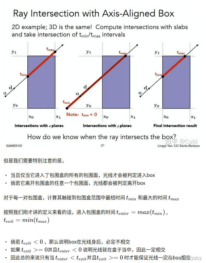
inline bool Bounds3::IntersectP(const Ray& ray, const Vector3f& invDir,
                                const std::array<int, 3>& dirIsNeg) const
{
    // invDir: ray direction(x,y,z), invDir=(1.0/x,1.0/y,1.0/z), use this because Multiply is faster that Division
    // dirIsNeg: ray direction(x,y,z), dirIsNeg=[int(x>0),int(y>0),int(z>0)], use this to simplify your logic
    // TODO test if ray bound intersects

    const auto& origin = ray.origin;
	float tEnter = -std::numeric_limits<float>::infinity();
	float tExit = std::numeric_limits<float>::infinity();

    for(int i = 0; i < 3; ++i){
        float min = (pMin[i] - origin[i]) * invDir[i];
        float max = (pMax[i] - origin[i]) * invDir[i];
        if(!dirIsNeg[i]){
            std::swap(min, max);
        }
        tEnter = std::max(tEnter, min);
        tExit = std::min(tExit, max);
    }
    if(tEnter < tExit && tExit >= 0){
        return true;
    }
    return false;

}
- 递归寻找光线和物体的交点
Intersection BVHAccel::getIntersection(BVHBuildNode* node, const Ray& ray) const
{
    // TODO Traverse the BVH to find intersection
    Intersection isect;

    std::array<int, 3> dirIsNeg { ray.direction.x > 0 , ray.direction.y > 0, ray.direction.z > 0};
    if(!node->bounds.IntersectP(ray, ray.direction_inv, dirIsNeg)){
        return isect;
    }
    if(node->left == nullptr && node->right == nullptr){
        isect = node->object->getIntersection(ray);
        return isect;
    }

    auto hit1 = getIntersection(node->left, ray);
    auto hit2 = getIntersection(node->right, ray);

    return hit1.distance < hit2.distance ? hit1 : hit2;
}
作业7
目标:实现path trcing的过程
作业框架和作业6差不多,但是光线追踪主体部分要根据伪代码书写:
 关于primary trays生成,应该是模型的坐标问题,所以生成光线和之前不同,不需要考虑太多:
void Renderer::Render(const Scene& scene)
{
    std::vector<Vector3f> framebuffer(scene.width * scene.height);

    float scale = tan(deg2rad(scene.fov * 0.5));
    float imageAspectRatio = scene.width / (float)scene.height;
    Vector3f eye_pos(278, 273, -800);
    int m = 0;

    // change the spp value to change sample ammount
    int spp = 16;
    std::cout << "SPP: " << spp << "\n";
    for (uint32_t j = 0; j < scene.height; ++j) {
        for (uint32_t i = 0; i < scene.width; ++i) {

            float rand_x = get_random_float();
            float rand_y = get_random_float();
            // generate primary ray direction
            float x = (2 * (i + rand_x) / (float)scene.width - 1) *
                      imageAspectRatio * scale;
            float y = (1 - 2 * (j + rand_y) / (float)scene.height) * scale;

            Vector3f dir = normalize(Vector3f(-x, y, 1));


            for (int k = 0; k < spp; k++){
                framebuffer[m] += scene.castRay(Ray(eye_pos, dir), 0) / spp;
            }
            m++;
        }
        UpdateProgress(j / (float)scene.height);
    }
    UpdateProgress(1.f);

    // save framebuffer to file
    FILE* fp = fopen("binary.ppm", "wb");
    (void)fprintf(fp, "P6\n%d %d\n255\n", scene.width, scene.height);
    for (auto i = 0; i < scene.height * scene.width; ++i) {
        static unsigned char color[3];
        color[0] = (unsigned char)(255 * std::pow(clamp(0, 1, framebuffer[i].x), 0.6f));
        color[1] = (unsigned char)(255 * std::pow(clamp(0, 1, framebuffer[i].y), 0.6f));
        color[2] = (unsigned char)(255 * std::pow(clamp(0, 1, framebuffer[i].z), 0.6f));
        fwrite(color, 1, 3, fp);
    }
    fclose(fp);
}
为了和课程讲解的方向保持一致,将光线方向取反,表示光线是从物体到达人眼,即对应wo,开始path trcing:
首先判断光线和场景的交点,无交点直接返回,有交点,开始trcing,
- 如果直接达到了光源,直接返回光源Emission
- 计算直接光照
- 计算间接光照
Vector3f Scene::shade(Intersection& inter , Vector3f wo) const
{
    //打到光源了
    if(inter.m->hasEmission()){
        return inter.m->getEmission();
    }

    const float epsilon = 0.0005f;
    //直接光照
    Vector3f Lo_dir;
    {
        float light_pdf;
        Intersection hit_light;
        sampleLight(hit_light, light_pdf);

        Vector3f obj2Light = hit_light.coords - inter.coords;
        Vector3f obj2LightDir = obj2Light.normalized();

        Ray r(inter.coords, obj2LightDir);

        auto t = intersect(r);
        //说明达到光源
        if(t.distance - obj2Light.norm() > -epsilon){
            Vector3f f_r = inter.m->eval(obj2LightDir, wo, inter.normal);
            float r2 = dotProduct(obj2Light, obj2Light);
            float cosA = std::max(0.f, dotProduct(inter.normal, obj2LightDir)) ;
            float cosB = std::max(0.f, dotProduct(hit_light.normal, -obj2LightDir));
            Lo_dir = hit_light.emit * f_r * cosA * cosB / r2 / light_pdf;
        }
    }
    //间接光照
    Vector3f Lo_indir;
    {
        if (get_random_float() < RussianRoulette)
        {
            Vector3f dir2NextObj = inter.m->sample(wo, inter.normal.normalized());
            float pdf = inter.m->pdf(wo, dir2NextObj, inter.normal);
            if(pdf > epsilon){
                Intersection nextObj = intersect(Ray(inter.coords, dir2NextObj));
                if(nextObj.happened && !nextObj.m->hasEmission()){
                    Vector3f f_r = inter.m->eval(dir2NextObj, wo, inter.normal);
                    float cos = std::max(.0f, dotProduct(dir2NextObj, inter.normal));
                    Lo_indir = shade(nextObj, -dir2NextObj) * f_r * cos / pdf / RussianRoulette;
                }
            }
        }
    }
    return Lo_dir + Lo_indir;

}

// Implementation of Path Tracing
Vector3f Scene::castRay(const Ray &ray, int depth) const
{
    // TO DO Implement Path Tracing Algorithm here
	auto hitObj = intersect(ray);
	if (!hitObj.happened) return {};
    return shade(hitObj,-ray.direction);

}


 1127
1127


 被折叠的 条评论
为什么被折叠?
被折叠的 条评论
为什么被折叠?
 到【灌水乐园】发言


