


 文章探讨了电阻应变片在测量力学性能中的局限性,介绍了数字图像相关法(DIC)作为全场测量工具的优势,通过XTDIC三维全场应变测量系统进行实际测试,展示了其与传统应变片在压力加载测试中的高精度。实验结果显示,XTDIC测量精度与应变片数据相差在20微应变内,证实了其在科研和工程领域的广泛应用。
当一个新的材料从单个产生到行业应用,其中力学性能检测是必不可少的一环。材料受力后会产生变形,变形到一定程度即发生断裂,这种在外载作用下材料发生材料变形与断裂的行为,即为材料的力学性能。
电阻应变片的诞生,让材料的力学性能定量描述成为了现实。金属电阻材料受到外部拉伸力或压缩力时,就被拉伸或缩短,其电阻值亦随之增加或降低。
然而,应变片也有不足的地方,单应变片仅能测量单个方向的应变;大幅面工程测量需采用应变花,但引线非常会增加额外质量;另外,对于特殊材料表面,或者在特殊环境(温度、湿度等)下,应变片有诸多使用限制。
-01-
DIC与传统测量技术
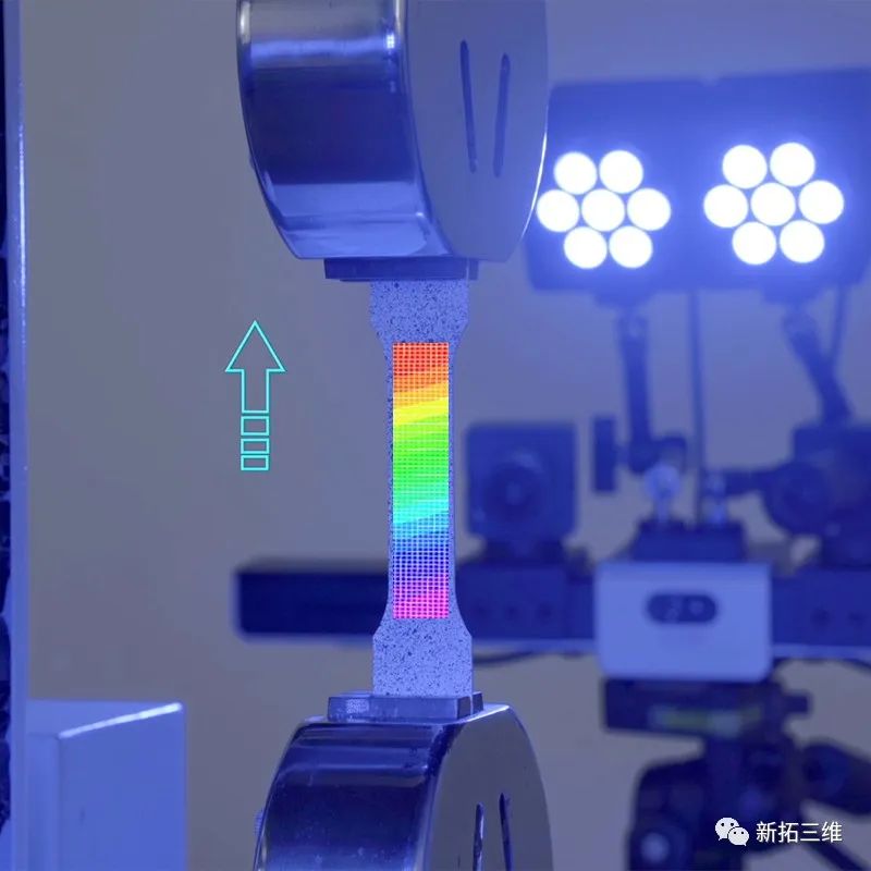
数字图像相关法(DIC)基本原理是摄像机采集物体在同一时刻的散斑图像,经过匹配、重建得到物体表面点的三维坐标,比较这些点在变形前、后的三维坐标变化,得到物体表面点的位移和变形。
与传统传感器(如应变仪)的点测量不同,DIC技术能够对三维变形形状进行全场分析,可以在一个区域内提供来自更多数据点的测量数据,而不会干扰物体本身的自重和载荷情况。
对于测量设备来说,测量精度是至关重要的。DIC技术的精度主要由硬件参数、理论算法、以及测试距离以及视场宽度决定。那么,DIC全场应变测量设备在实际测试中的精度是多少?与接触式应变片测量相比,它的表现又怎么样呢?下面通过一个加压变形测试案例,为大家展示DIC技术的测量精度与数据可靠性。
新拓三维XTDIC三维全场应变测量系统,可以测量材料表面及结构的力学表征,通过DIC软件计算输出材料表面的位移场、应变场等数据,可分析材料在加载过程中裂纹萌生、演化、扩展和弹塑性阶段的动态变化,稳定可靠的测试数据有助于科研人员更高效、精确地完成研发测试。
-02-
零部件受压加载变形测试
为了验证DIC技术的测量精度,对结构部件在实际工况下进行抗压强度测试,分析受压加载关键区域的变形情况,通过与应变片比较测量精度情况。
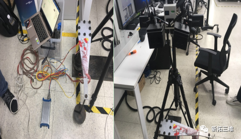
在结构部件表面粘贴应变片,采用XTDIC三维全场应变测量系统进行图像采集,将应变片测试数据与DIC测量结果进行比较,通过实际测试数据验证DIC仪器设备的测量精度。
-03-
DIC测量数据与应变片数采对比
测试过程,首先输出DIC测量应变场,绘制出关键点应变;然后,用DIC测量数据与实际应变片数据进行对比,可以看到XTDIC三维全场应变测量系统输出的数据与应变片值吻合很好,两者应变差别在20με以内。
-04-
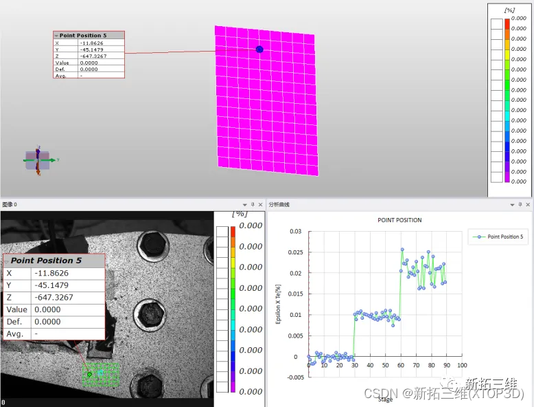
DIC测量数据-应变场解算
DIC测量数据-应变场解算
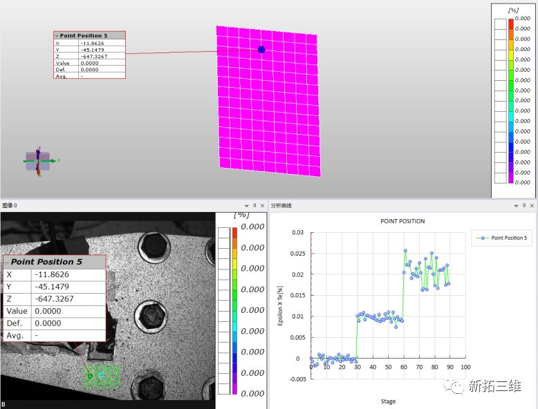
如图所示,在DIC软件中将该点数据导出,可在EXCEL表格绘制出该点应变:
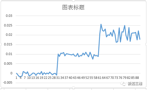
从上图可以看出,结构部件加压一共分为两个阶段,在三个不同位置DIC测量输出的平均应变数据分别为:
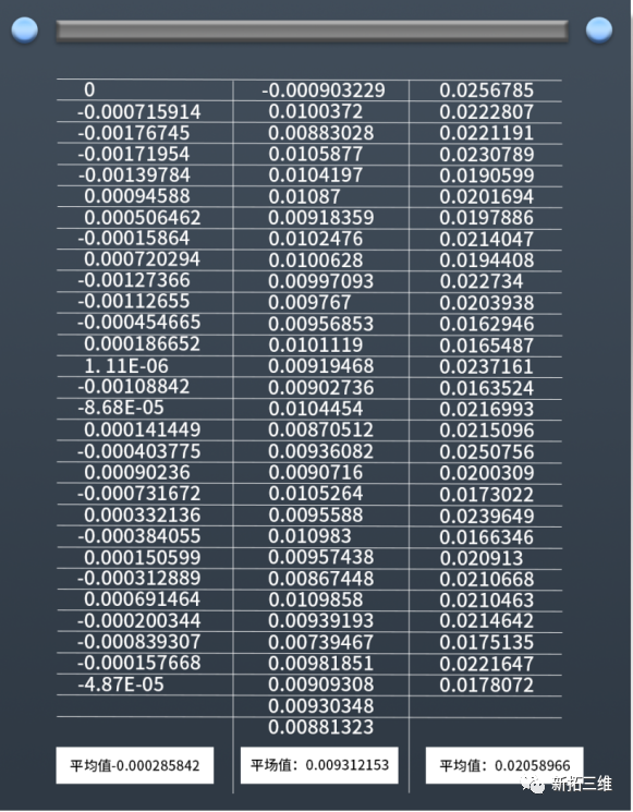
在三个不同加压状态下,DIC测量出来的应变数据分别为:0.000285%(0.285微应变)、0.00931%(93.1微应变)、0.0205896(205.896微应变)。
在三个不同加压状态下,对应应变片测出来的数据为:0.206微应变,73.552微应变,217.215微应变(如下面应变片数采图所示)。根据对比,两者应变相差分别为0.085微应变,19.5微应变,11.3微应变,则应变精度相差均在20微应变之内。
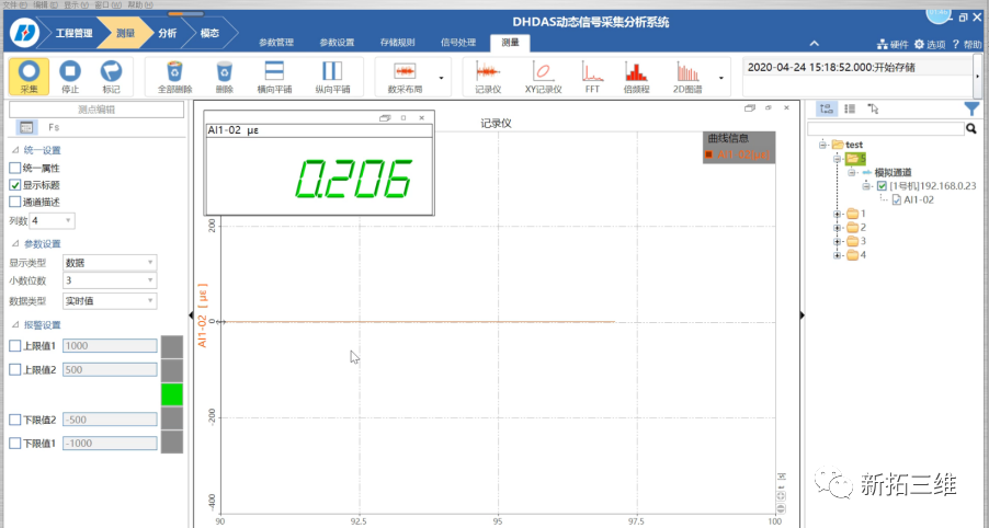
静止状态应变片数采图
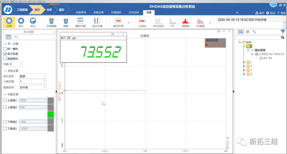
第一次加压应变片数采图

第二次加压应变片数采图
综上所述,经过三组加压实验测试,新拓三维XTDIC三维全场应变测量系统测试精度与应变片数采精度验证对比,应变数据大小差距在20个微应变之内。
DIC方法被广泛应用于常规静态测量、高速冲击测量、疲劳全场测量、瞬态振动与模态测量、3D温度场与应变场耦合、微小尺寸材料力学性能测量之中,在科研领域与工程应用领域已经受到了众多科研工作者、工程师的认可。
English translation
When a new material is produced from a single material to an industrial application, mechanical property testing is an indispensable part. The material will be deformed after being stressed, and the deformation will occur to a certain extent, which is the mechanical properties of the material.
The birth of electrical strain gauges has made the quantitative description of the mechanical properties of materials a reality. When a metal resistive material is subjected to an external tensile or compressive force, it is stretched or shortened, and its resistance value increases or decreases.
However, there are also disadvantages of strain gauges, a single strain gauge can only measure strain in a single direction, large-format engineering measurements require the use of strain gauge rosettes, but the leads add extra mass, and there are many limitations on the use of strain gauges for special material surfaces or in special environments (temperature, humidity, etc.).
-01-
DIC vs. conventional measurement technology
The basic principle of digital image correlation method (DIC) is that the camera collects speckle images of objects at the same time, and obtains the 3D coordinates of the surface points of the object through matching and reconstruction, and compares the 3D coordinate changes of these points before and after deformation to obtain the displacement and deformation of the surface points of the object.
Unlike point measurements from traditional sensors, such as strain gauges, DIC technology enables full-field analysis of 3D deformation shapes, providing measurement data from more data points in a single area without interfering with the self-weight and load profile of the object itself.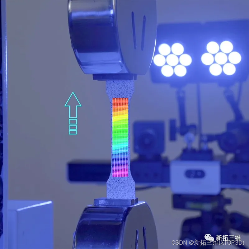
Measurement accuracy is crucial for measuring equipment. The accuracy of DIC technology is mainly determined by hardware parameters, theoretical algorithms, test distance and field of view. So, what is the accuracy of DIC full-field strain measurement equipment in actual testing, and how does it perform compared to contact strain gauge measurement? The following is a pressure deformation test case to show you the measurement accuracy and data reliability of DIC technology.
XTOP 3D XTDIC 3D full-field strain measurement system can measure the mechanical characterization of material surface and structure, calculate and output the displacement field, strain field and other data of the material surface through DIC software, and analyze the dynamic changes of crack initiation, evolution, propagation and elastoplastic stage of the material during the loading process, and the stable and reliable test data will help researchers complete the R&D test more efficiently and accurately.
-02-
Deformation test of parts under pressure loading
In order to verify the measurement accuracy of DIC technology, the compressive strength of structural components was tested under actual working conditions, the deformation of the key areas under pressure loading was analyzed, and the measurement accuracy was compared with the strain gauge.
The strain gauge is pasted on the surface of the structural components, and the XTDIC 3D full-field strain measurement system is used for image acquisition, and the test data of the strain gauge is compared with the DIC measurement results, and the measurement accuracy of the DIC instrument is verified through the actual test data.
-03-
DIC measurement data was compared with the number of strain gauges
Then, by comparing the DIC measurement data with the actual strain gauge data, it can be seen that the data output by the XTDIC 3D full-field strain measurement system is in good agreement with the strain gauge value, and the strain difference between the two is within 20με.
-04-
DIC measurement data - strain field solving
DIC measurement data - strain field solving
As shown in the figure,Export the point data in DIC software,This point strain can be plotted in an Excel sheet:
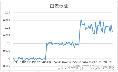
As can be seen from the figure above, the pressurization of structural components is divided into two stages, and the average strain data output from DIC measurements at three different positions are as follows:
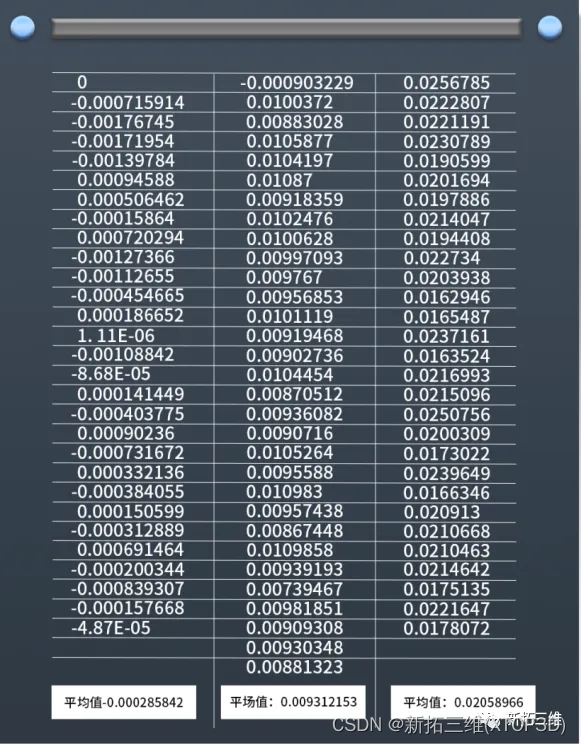
Under three different pressurized conditions, the strain data measured by DIC were 0.000285% (0.285 microstrain), 0.00931% (93.1 microstrain), and 0.0205896 (205.896 microstrain).
Under three different pressurized conditions, the measured data of the strain gauge are 0.206 microstrain, 73.552 microstrain, and 217.215 microstrain (as shown in the following figure of the number of strain gauges). According to the comparison, the difference between the two strains is 0.085 microstrain, 19.5 microstrain, and 11.3 microstrain, respectively, and the difference in strain accuracy is within 20 microstrain.
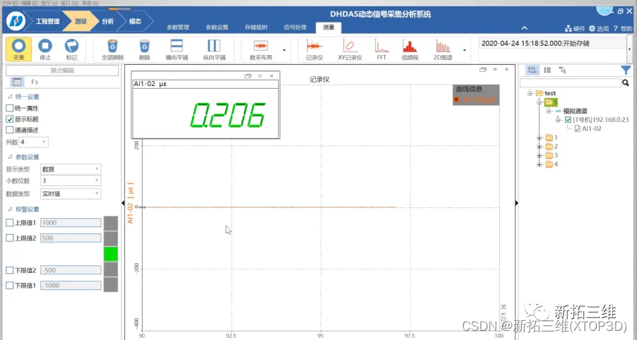
The number of strain gauges in the stationary state is taken
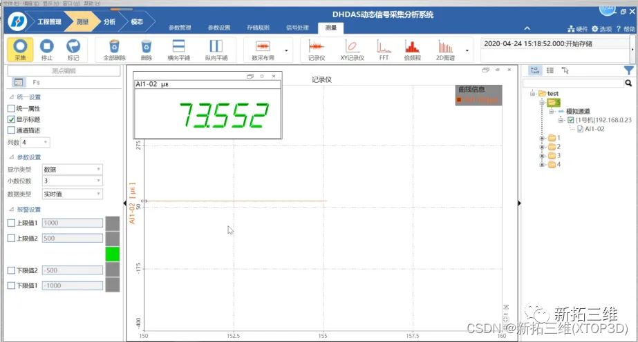
The number of pressurized strain gauges for the first time was taken
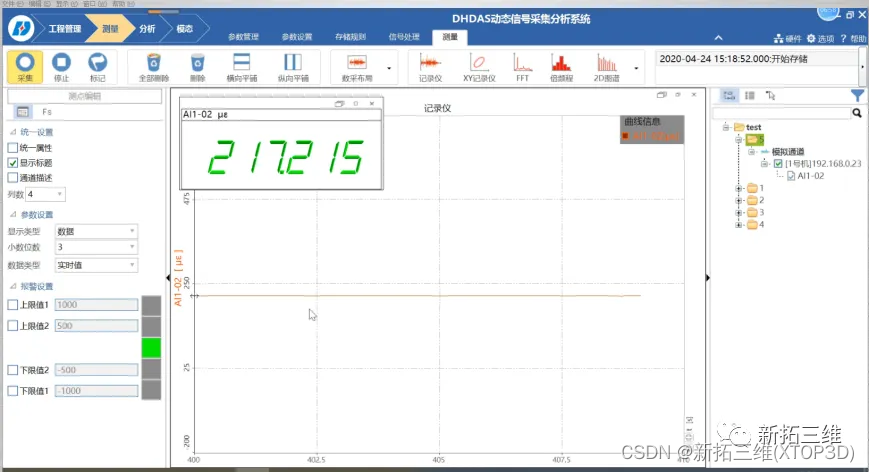 The number of pressurized strain gauges was taken for the second time
To sum up, after three sets of pressurization experiments, the test accuracy of the XTDIC 3D full-field strain measurement system of XTOP 3D is verified and compared with the accuracy of the strain gauge numerical acquisition, and the difference in the size of the strain data is within 20 microstrains.
The DIC method is widely used in conventional static measurement, high-speed shock measurement, fatigue full-field measurement, transient vibration and modal measurement, 3D temperature field and strain field coupling, and micro-size material mechanical property measurement, and has been recognized by many scientific researchers and engineers in the field of scientific research and engineering applications.


 4万+
4万+

 被折叠的 条评论
为什么被折叠?
被折叠的 条评论
为什么被折叠?
 到【灌水乐园】发言


