


- 新建SSC文件,参考EtherCAT Slave Desi Quick Guide 和 《ETG2000_S_R_V1i0i6_EtherCATSlaveInformationSpecification.pdf》
- SSC配置参考博主博文SSC从站
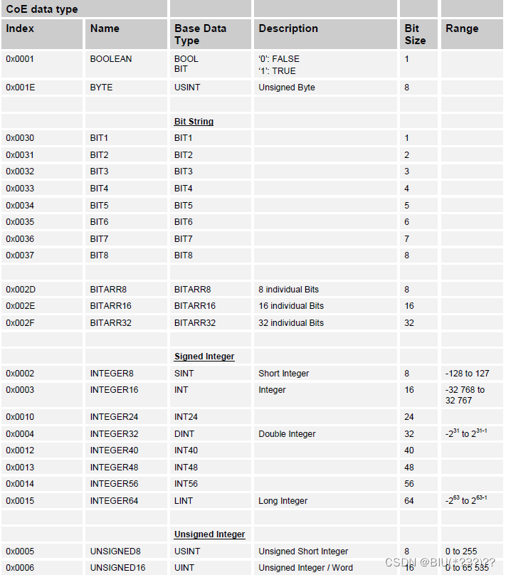
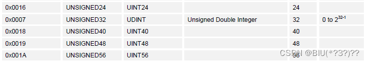
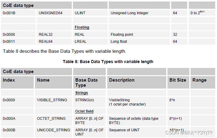
- EtherCAT基本数据类型
SSC生成代码
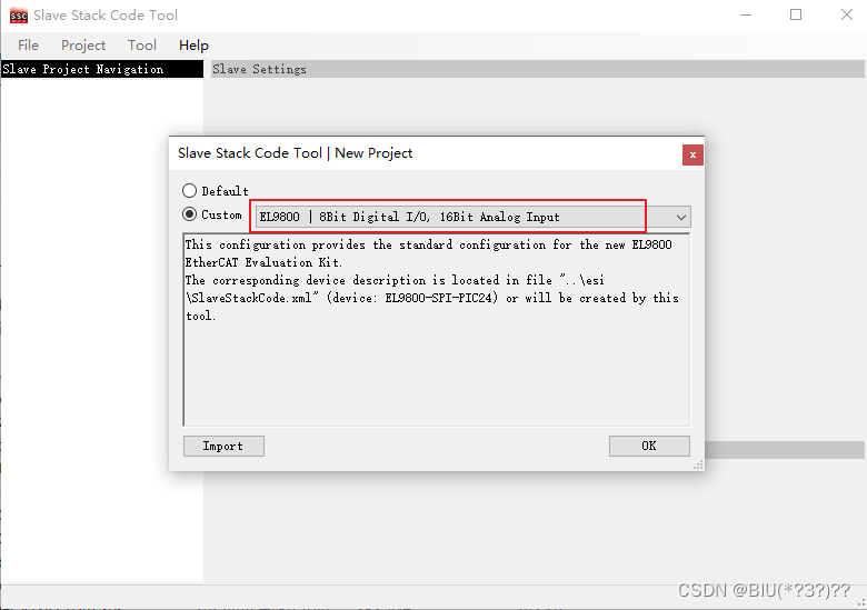
- 新建SSC文件(建议使用SSC 5.12版本,相对5.11版本需要修改内容更少一点)
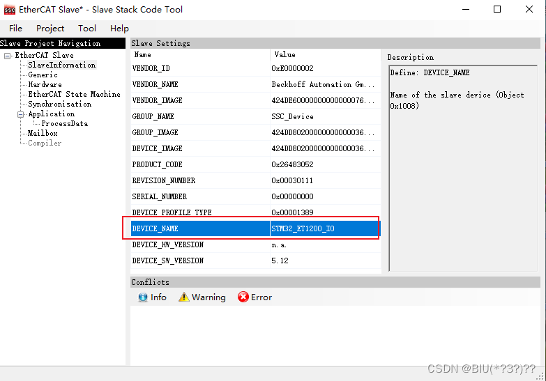
- SlaveInformation 修改
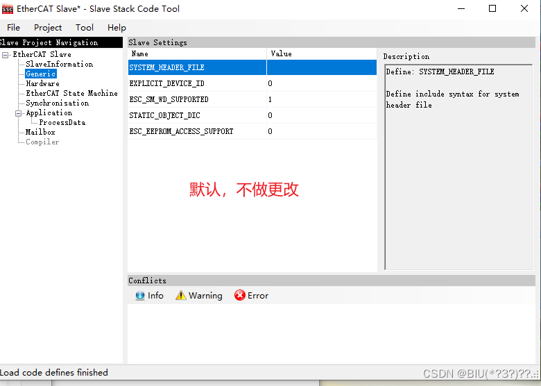
- Generic保持不变
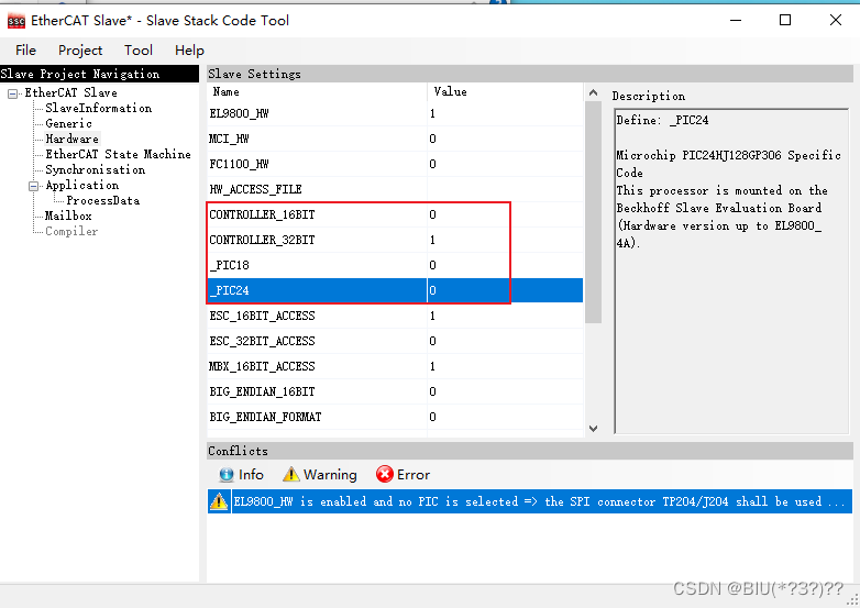
- HardWare修改,适配STM32
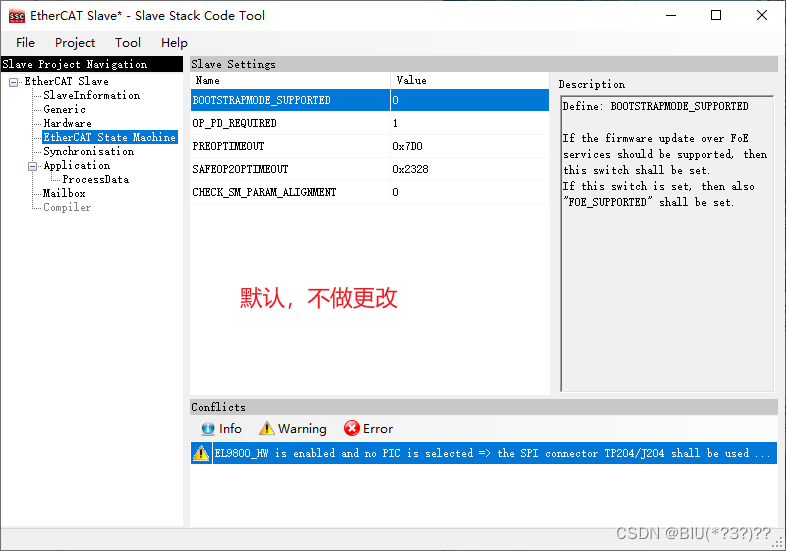
- EtherCAT State Machine 保持不变
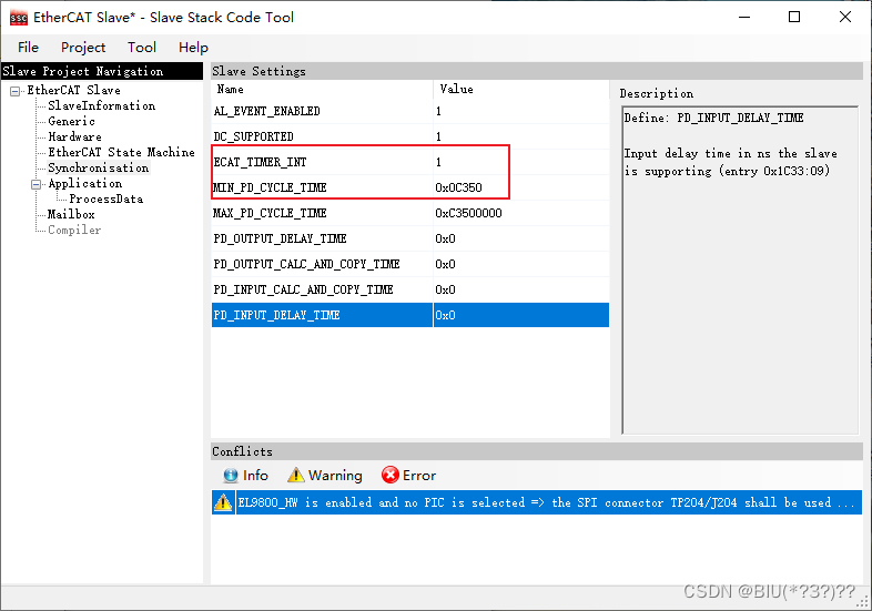
- Synchronisation 修改:增加1ms定时器,用于EtherCAT看门狗
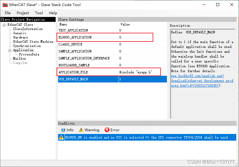
- Application 修改:不使用el9800app,c,增加头文件包含。(保存后再打开该项会变少)
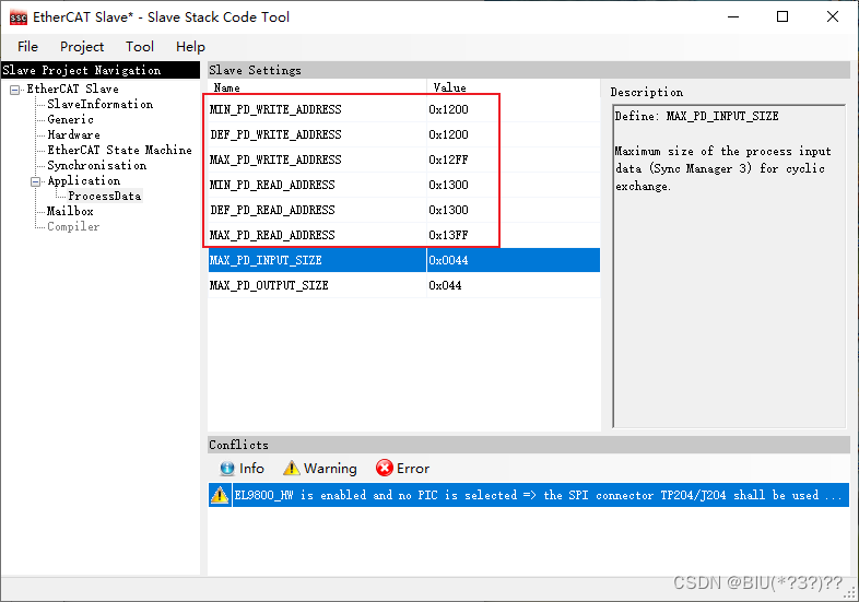
- ProcessData 修改:修改PDO数据传输地址
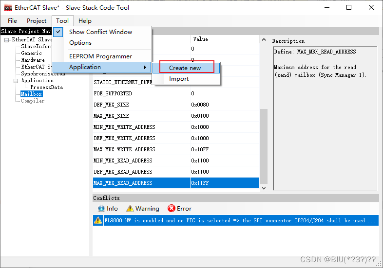
- MailBox 修改:修改SM传输地址
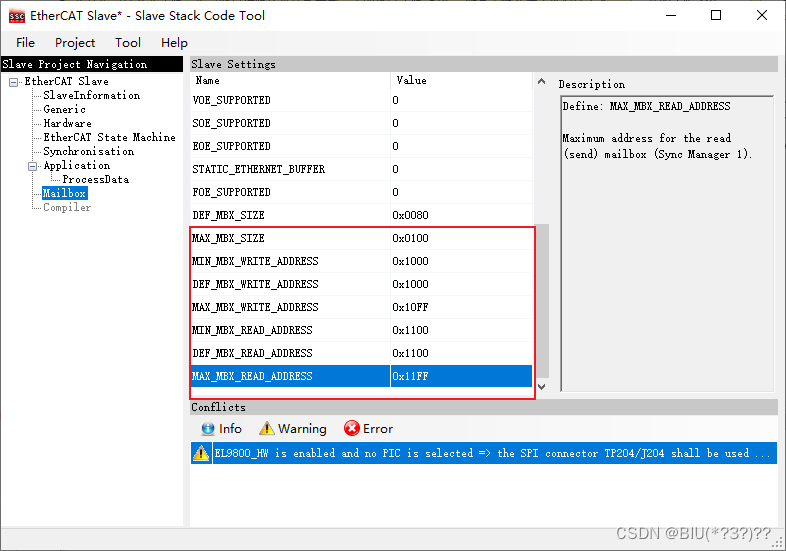
ET1200只有1K内存,范围0x1000~0x1400;0x1000~0x11FF 分配给邮箱,0x1200~0x13FF分配给PDO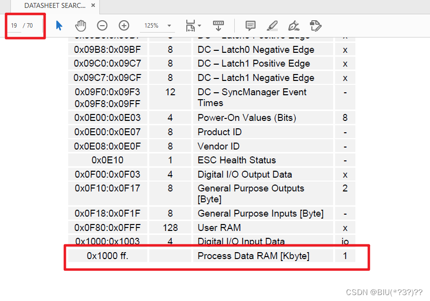
- 添加PDO变量
- 在打开的Excel表格中添加要传输的PDO变量
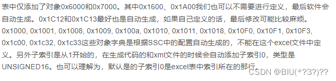
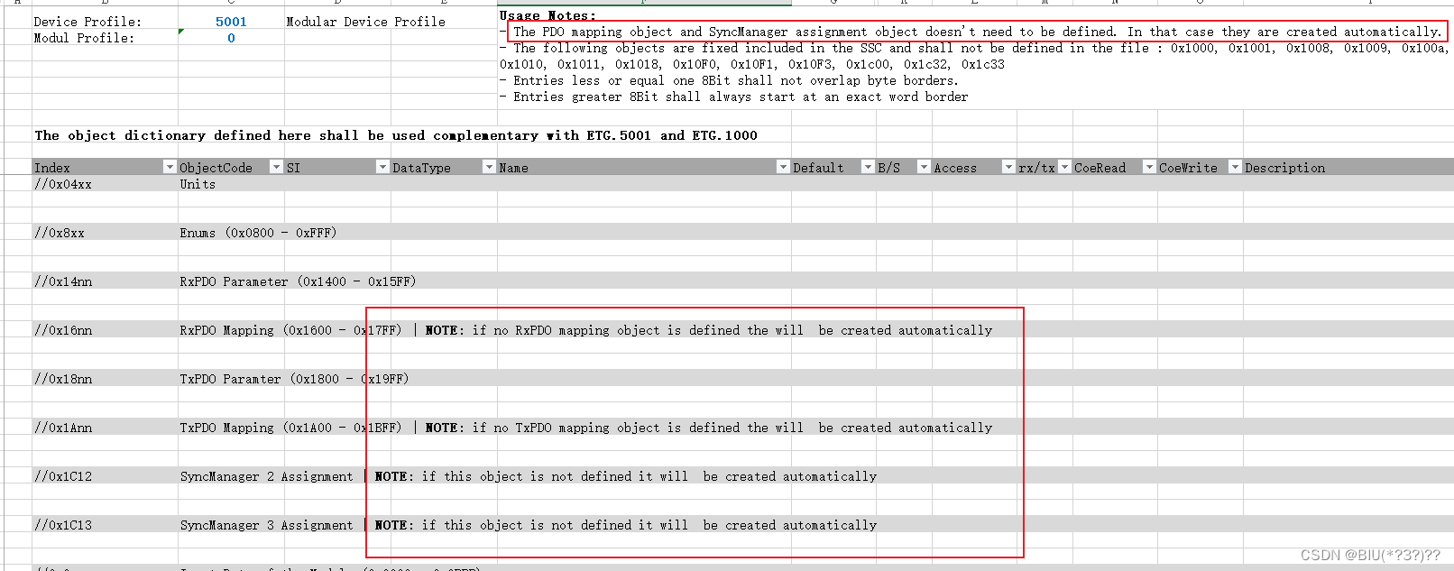
- 映射部分地址会自动生成,无需添加,只需要添加0x6000和0x7000的PDO就行
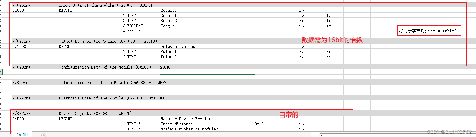
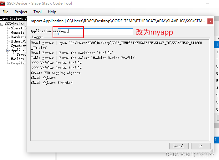
- 保存并改名为myapp
- 生成EtherCAT代码
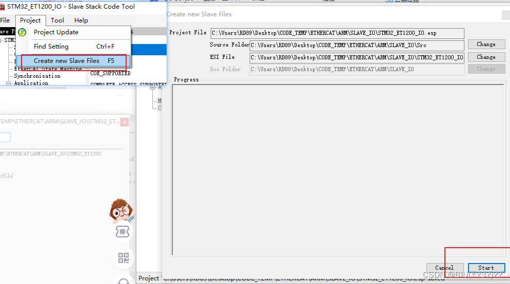
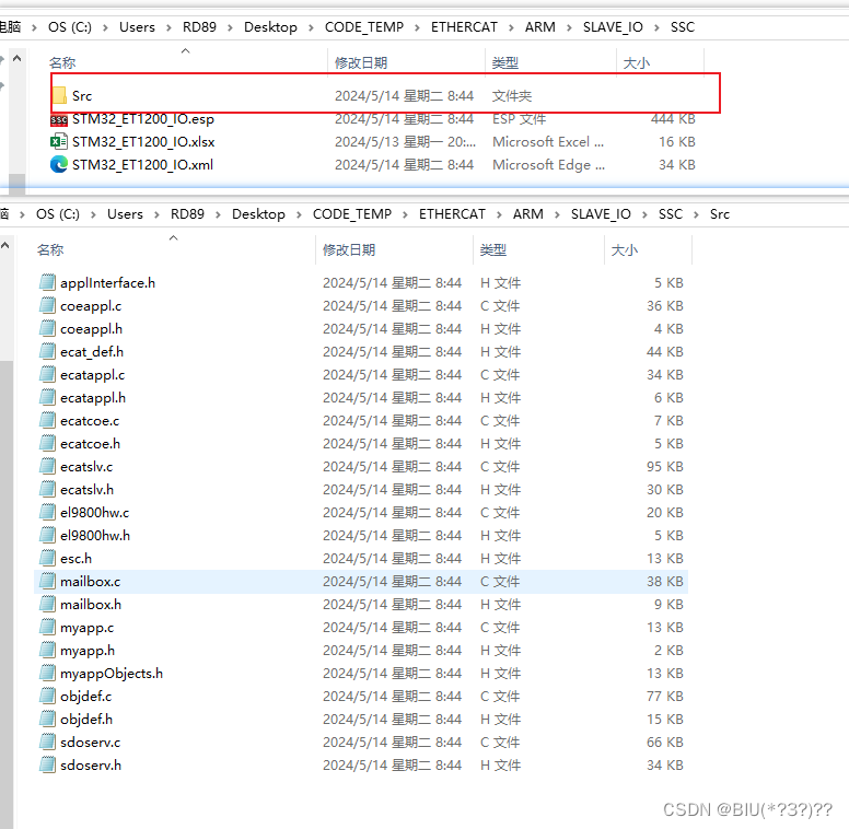
- 生成代码及位置如下所示
从站操作,修改STM32相应程序
将生成的代码文件导入项目中,项目列表如下图。主函数在myapp.c的最底部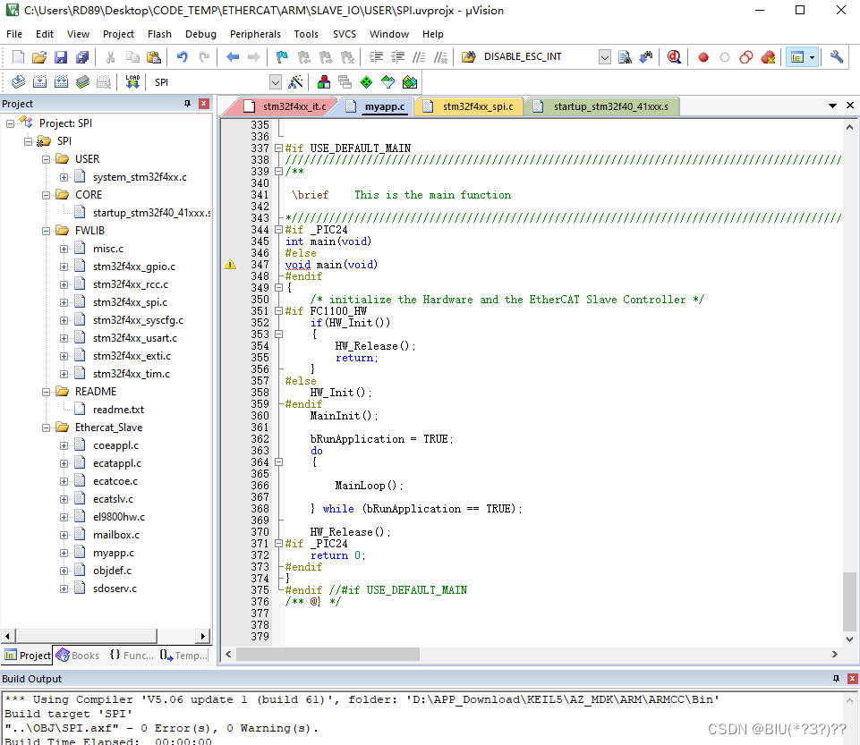 修改el9800hw.c文件:
- 根据报错去添加define(由于没有用到SYNC1,所以SYNC1的定义不做任何处理)
- 添加spi、timer和exit初始化函数
- 修改RxTxSpiData函数,改成SPI先发送后接收函数
- 增加定时器中断处理函数
/*
* This source file is part of the EtherCAT Slave Stack Code licensed by Beckhoff Automation GmbH & Co KG, 33415 Verl, Germany.
* The corresponding license agreement applies. This hint shall not be removed.
*/

/**
\addtogroup EL9800_HW EL9800 Platform (Serial ESC Access)
@{
*/

/**
\file    el9800hw.c
\author EthercatSSC@beckhoff.com
\brief Implementation
Hardware access implementation for EL9800 onboard PIC18/PIC24 connected via SPI to ESC

\version 5.12

<br>Changes to version V5.11:<br>
V5.12 EL9800 1: improve the SPI access<br>
<br>Changes to version V5.10:<br>
V5.11 ECAT10: change PROTO handling to prevent compiler errors<br>
V5.11 EL9800 2: change PDI access test to 32Bit ESC access and reset AL Event mask after test even if AL Event is not enabled<br>
<br>Changes to version V5.01:<br>
V5.10 ESC5: Add missing swapping<br>
V5.10 HW3: Sync1 Isr added<br>
V5.10 HW4: Add volatile directive for direct ESC DWORD/WORD/BYTE access<br>
           Add missing swapping in mcihw.c<br>
           Add "volatile" directive vor dummy variables in enable and disable SyncManger functions<br>
           Add missing swapping in EL9800hw files<br>
<br>Changes to version V5.0:<br>
V5.01 HW1: Invalid ESC access function was used<br>
<br>Changes to version V4.40:<br>
V5.0 ESC4: Save SM disable/Enable. Operation may be pending due to frame handling.<br>
<br>Changes to version V4.30:<br>
V4.40 : File renamed from spihw.c to el9800hw.c<br>
<br>Changes to version V4.20:<br>
V4.30 ESM: if mailbox Syncmanger is disabled and bMbxRunning is true the SyncManger settings need to be revalidate<br>
V4.30 EL9800: EL9800_x hardware initialization is moved to el9800.c<br>
V4.30 SYNC: change synchronisation control function. Add usage of 0x1C32:12 [SM missed counter].<br>
Calculate bus cycle time (0x1C32:02 ; 0x1C33:02) CalcSMCycleTime()<br>
V4.30 PDO: rename PDO specific functions (COE_xxMapping -> PDO_xxMapping and COE_Application -> ECAT_Application)<br>
V4.30 ESC: change requested address in GetInterruptRegister() to prevent acknowledge events.<br>
(e.g. reading an SM config register acknowledge SM change event)<br>
GENERIC: renamed several variables to identify used SPI if multiple interfaces are available<br>
V4.20 MBX 1: Add Mailbox queue support<br>
V4.20 SPI 1: include SPI RxBuffer dummy read<br>
V4.20 DC 1: Add Sync0 Handling<br>
V4.20 PIC24: Add EL9800_4 (PIC24) required source code<br>
V4.08 ECAT 3: The AlStatusCode is changed as parameter of the function AL_ControlInd<br>
<br>Changes to version V4.02:<br>
V4.03 SPI 1: In ISR_GetInterruptRegister the NOP-command should be used.<br>
<br>Changes to version V4.01:<br>
V4.02 SPI 1: In HW_OutputMapping the variable u16OldTimer shall not be set,<br>
             otherwise the watchdog might exceed too early.<br>
<br>Changes to version V4.00:<br>
V4.01 SPI 1: DI and DO were changed (DI is now an input for the uC, DO is now an output for the uC)<br>
V4.01 SPI 2: The SPI has to operate with Late-Sample = FALSE on the Eva-Board<br>
<br>Changes to version V3.20:<br>
V4.00 ECAT 1: The handling of the Sync Manager Parameter was included according to<br>
              the EtherCAT Guidelines and Protocol Enhancements Specification<br>
V4.00 APPL 1: The watchdog checking should be done by a microcontroller<br>
                 timer because the watchdog trigger of the ESC will be reset too<br>
                 if only a part of the sync manager data is written<br>
V4.00 APPL 4: The EEPROM access through the ESC is added

*/


/*--------------------------------------------------------------------------------------
------
------    Includes
------
--------------------------------------------------------------------------------------*/
#include "ecat_def.h"

#include "ecatslv.h"


#define    _EL9800HW_ 1
#include "el9800hw.h"
#undef    _EL9800HW_
/*remove definition of _EL9800HW_ (#ifdef is used in el9800hw.h)*/

#include "ecatappl.h"


/*--------------------------------------------------------------------------------------
------
------    internal Types and Defines
------
--------------------------------------------------------------------------------------*/

typedef union
{
    unsigned short    Word;
    unsigned char    Byte[2];
} UBYTETOWORD;

typedef union
{
    UINT8           Byte[2];
    UINT16          Word;
}
UALEVENT;

#define 	EtherCAT_SPIx				SPI1
#define 	SELECT_SPI					GPIO_ResetBits(GPIOE, GPIO_Pin_1);
#define 	DESELECT_SPI				GPIO_SetBits(GPIOE, GPIO_Pin_1);
#define 	ETHERCAT_SPI_INIT			SPI1_Init()

#define		EscIsr					EXTI0_IRQHandler
#define		Sync0Isr				EXTI15_10_IRQHandler
#define		Sync1Isr				EXTI9_5_IRQHandler
#define		TimerIsr				TIM2_IRQHandler

#define		ACK_TIMER_INT			TIM_ClearITPendingBit(TIM2,TIM_IT_Update);

#define 	INIT_ESC_INT			Esc_Init();
#define 	INIT_SYNC0_INT			SYNC0_Init();
#define 	INIT_SYNC1_INT

#define    	ENABLE_SYNC0_INT
#define    	ENABLE_SYNC1_INT

#define    	INIT_ECAT_TIMER			TIM2_Init(1000-1,168-1)
#define    	START_ECAT_TIMER		TIM_Cmd(TIM2, ENABLE)

#define    	ENABLE_GLOBAL_INT		__enable_irq()
#define		DISABLE_GLOBAL_INT		__disable_irq()

#define 	ACK_ESC_INT				EXTI_ClearITPendingBit(EXTI_Line0);
#define 	ACK_SYNC0_INT			EXTI_ClearITPendingBit(EXTI_Line12);
#define 	ACK_SYNC1_INT

#define		Nop()					__NOP()


/*-----------------------------------------------------------------------------------------
------
------    SPI defines/macros
------
-----------------------------------------------------------------------------------------*/
void SPI1_Init(void)
{

	GPIO_InitTypeDef  GPIO_InitStructure;
	SPI_InitTypeDef  SPI_InitStructure;

	RCC_AHB1PeriphClockCmd(RCC_AHB1Periph_GPIOB|RCC_AHB1Periph_GPIOE, ENABLE);//使能GPIOA时钟
	RCC_APB2PeriphClockCmd(RCC_APB2Periph_SPI1, ENABLE);//使能SPI1时钟

	//GPIOFB3,4,5初始化设置
	GPIO_InitStructure.GPIO_Pin = GPIO_Pin_3|GPIO_Pin_4|GPIO_Pin_5;//PB3~5复用功能输出
	GPIO_InitStructure.GPIO_Mode = GPIO_Mode_AF;//复用功能
	GPIO_InitStructure.GPIO_OType = GPIO_OType_PP;//推挽输出
	GPIO_InitStructure.GPIO_Speed = GPIO_Speed_100MHz;//100MHz
	GPIO_InitStructure.GPIO_PuPd = GPIO_PuPd_UP;//上拉
	GPIO_Init(GPIOB, &GPIO_InitStructure);//初始化

	GPIO_PinAFConfig(GPIOB,GPIO_PinSource3,GPIO_AF_SPI1); //PB3复用为 SPI1
	GPIO_PinAFConfig(GPIOB,GPIO_PinSource4,GPIO_AF_SPI1); //PB4复用为 SPI1
	GPIO_PinAFConfig(GPIOB,GPIO_PinSource5,GPIO_AF_SPI1); //PB5复用为 SPI1

	//这里只针对SPI口初始化
	RCC_APB2PeriphResetCmd(RCC_APB2Periph_SPI1,ENABLE);//复位SPI1
	RCC_APB2PeriphResetCmd(RCC_APB2Periph_SPI1,DISABLE);//停止复位SPI1

	SPI_InitStructure.SPI_Direction = SPI_Direction_2Lines_FullDuplex;  //设置SPI单向或者双向的数据模式:SPI设置为双线双向全双工
	SPI_InitStructure.SPI_Mode = SPI_Mode_Master;		//设置SPI工作模式:设置为主SPI
	SPI_InitStructure.SPI_DataSize = SPI_DataSize_8b;		//设置SPI的数据大小:SPI发送接收8位帧结构
	SPI_InitStructure.SPI_CPOL = SPI_CPOL_High;		//串行同步时钟的空闲状态为高电平
	SPI_InitStructure.SPI_CPHA = SPI_CPHA_2Edge;	//串行同步时钟的第二个跳变沿(上升或下降)数据被采样
	SPI_InitStructure.SPI_NSS = SPI_NSS_Soft;		//NSS信号由硬件(NSS管脚)还是软件(使用SSI位)管理:内部NSS信号有SSI位控制
	SPI_InitStructure.SPI_BaudRatePrescaler = SPI_BaudRatePrescaler_4;		//定义波特率预分频的值:波特率预分频值为256
	SPI_InitStructure.SPI_FirstBit = SPI_FirstBit_MSB;	//指定数据传输从MSB位还是LSB位开始:数据传输从MSB位开始
	SPI_InitStructure.SPI_CRCPolynomial = 7;	//CRC值计算的多项式
	SPI_Init(SPI1, &SPI_InitStructure);  //根据SPI_InitStruct中指定的参数初始化外设SPIx寄存器

	SPI_Cmd(SPI1, ENABLE); //使能SPI外设
	/********************************SEL*********************************************/
	GPIO_InitStructure.GPIO_Pin = GPIO_Pin_1;
	GPIO_InitStructure.GPIO_Mode = GPIO_Mode_OUT;
	GPIO_InitStructure.GPIO_OType = GPIO_OType_PP;//推挽输出
	GPIO_InitStructure.GPIO_Speed = GPIO_Speed_100MHz;//100MHz
	GPIO_InitStructure.GPIO_PuPd = GPIO_PuPd_UP;//上拉
	GPIO_Init(GPIOE, &GPIO_InitStructure);//初始化
}


/*-----------------------------------------------------------------------------------------
------
------    Global Interrupt setting
------
-----------------------------------------------------------------------------------------*/

/*-----------------------------------------------------------------------------------------
------
------    ESC Interrupt
------
-----------------------------------------------------------------------------------------*/
void Esc_Init(void)
{
	NVIC_InitTypeDef   NVIC_InitStructure;
	EXTI_InitTypeDef   EXTI_InitStructure;
	GPIO_InitTypeDef  GPIO_InitStructure;

	RCC_AHB1PeriphClockCmd(RCC_AHB1Periph_GPIOE, ENABLE);//使能GPIOA,GPIOE时钟

	GPIO_InitStructure.GPIO_Pin = GPIO_Pin_0;//WK_UP对应引脚PA0
	GPIO_InitStructure.GPIO_Mode = GPIO_Mode_IN;//普通输入模式
	GPIO_InitStructure.GPIO_PuPd = GPIO_PuPd_UP ;
	GPIO_InitStructure.GPIO_Speed = GPIO_Speed_100MHz;//100M
	GPIO_Init(GPIOE, &GPIO_InitStructure);//初始化GPIOA0

	RCC_APB2PeriphClockCmd(RCC_APB2Periph_SYSCFG, ENABLE);//使能SYSCFG时钟
	SYSCFG_EXTILineConfig(EXTI_PortSourceGPIOE, EXTI_PinSource0);//PA0 连接到中断线0
	/* 配置EXTI_Line2,3,4 */
	EXTI_InitStructure.EXTI_Line = EXTI_Line0;//LINE0
	EXTI_InitStructure.EXTI_Mode = EXTI_Mode_Interrupt;//中断事件
	EXTI_InitStructure.EXTI_Trigger = EXTI_Trigger_Falling; //下降沿触发
	EXTI_InitStructure.EXTI_LineCmd = ENABLE;//中断线使能
	EXTI_Init(&EXTI_InitStructure);//配置

	NVIC_InitStructure.NVIC_IRQChannel = EXTI0_IRQn;//外部中断0
	NVIC_InitStructure.NVIC_IRQChannelPreemptionPriority = 0x05;//抢占优先级0
	NVIC_InitStructure.NVIC_IRQChannelSubPriority = 0x00;//子优先级2
	NVIC_InitStructure.NVIC_IRQChannelCmd = ENABLE;//使能外部中断通道
	NVIC_Init(&NVIC_InitStructure);//配置

}


/*-----------------------------------------------------------------------------------------
------
------    SYNC0 Interrupt
------
-----------------------------------------------------------------------------------------*/
void SYNC0_Init(void)
{
	GPIO_InitTypeDef GPIO_InitStructure;
	NVIC_InitTypeDef   NVIC_InitStructure;
	EXTI_InitTypeDef   EXTI_InitStructure;

	RCC_AHB1PeriphClockCmd(RCC_AHB1Periph_GPIOA, ENABLE);//使能GPIOA,GPIOE时钟

	GPIO_InitStructure.GPIO_Pin = GPIO_Pin_12;//WK_UP对应引脚PA0
	GPIO_InitStructure.GPIO_Mode = GPIO_Mode_IN;//普通输入模式
	GPIO_InitStructure.GPIO_Speed = GPIO_Speed_100MHz;//100M
	GPIO_InitStructure.GPIO_PuPd = GPIO_PuPd_UP ;//下拉
	GPIO_Init(GPIOA, &GPIO_InitStructure);//初始化GPIOA0

	RCC_APB2PeriphClockCmd(RCC_APB2Periph_SYSCFG, ENABLE);//使能SYSCFG时钟
	SYSCFG_EXTILineConfig(EXTI_PortSourceGPIOA, EXTI_PinSource12);//PA12 连接到中断线12
	/* 配置EXTI_Line2,3,4 */
	EXTI_InitStructure.EXTI_Line = EXTI_Line12;//LINE0
	EXTI_InitStructure.EXTI_Mode = EXTI_Mode_Interrupt;//中断事件
	EXTI_InitStructure.EXTI_Trigger = EXTI_Trigger_Falling; //下降沿触发
	EXTI_InitStructure.EXTI_LineCmd = ENABLE;//中断线使能
	EXTI_Init(&EXTI_InitStructure);//配置

	NVIC_InitStructure.NVIC_IRQChannel = EXTI15_10_IRQn;//外部中断0
	NVIC_InitStructure.NVIC_IRQChannelPreemptionPriority = 0x06;//抢占优先级0
	NVIC_InitStructure.NVIC_IRQChannelSubPriority = 0x00;//子优先级2
	NVIC_InitStructure.NVIC_IRQChannelCmd = ENABLE;//使能外部中断通道
	NVIC_Init(&NVIC_InitStructure);//配置

}


/*-----------------------------------------------------------------------------------------
------
------    Hardware timer
------
-----------------------------------------------------------------------------------------*/
void TIM2_Init(u16 arr,u16 psc)
{
	TIM_TimeBaseInitTypeDef TIM_TimeBaseInitStructure;
	NVIC_InitTypeDef NVIC_InitStructure;

	RCC_APB1PeriphClockCmd(RCC_APB1Periph_TIM2,ENABLE);  ///使能TIM3时钟

	TIM_TimeBaseInitStructure.TIM_Period = arr; 	//自动重装载值
	TIM_TimeBaseInitStructure.TIM_Prescaler=psc;  //定时器分频
	TIM_TimeBaseInitStructure.TIM_CounterMode=TIM_CounterMode_Up; //向上计数模式
	TIM_TimeBaseInitStructure.TIM_ClockDivision=TIM_CKD_DIV1;

	TIM_TimeBaseInit(TIM2,&TIM_TimeBaseInitStructure);//初始化TIM3
	TIM_Cmd(TIM2,ENABLE); //使能定时器3

	NVIC_InitStructure.NVIC_IRQChannel=TIM2_IRQn; //定时器3中断
	NVIC_InitStructure.NVIC_IRQChannelPreemptionPriority=0x07; //抢占优先级1
	NVIC_InitStructure.NVIC_IRQChannelSubPriority=0x00; //子优先级3
	NVIC_InitStructure.NVIC_IRQChannelCmd=ENABLE;
	NVIC_Init(&NVIC_InitStructure);
	NVIC_Init(&NVIC_InitStructure);

	TIM_ITConfig(TIM2,TIM_IT_Update,ENABLE);

}


/*-----------------------------------------------------------------------------------------
------
------    Configuration Bits
------
-----------------------------------------------------------------------------------------*/

/*-----------------------------------------------------------------------------------------
------
------    LED defines
------
-----------------------------------------------------------------------------------------*/

/*--------------------------------------------------------------------------------------
------
------    internal Variables
------
--------------------------------------------------------------------------------------*/
UALEVENT         EscALEvent;            //contains the content of the ALEvent register (0x220), this variable is updated on each Access to the Esc
/*--------------------------------------------------------------------------------------
------
------    internal functions
------
--------------------------------------------------------------------------------------*/


/*****************************************************************/
/******************************************************************

如果硬件配置有变动,只需修改上面的函数和定义,下面的函数无需改动

******************************************************************/
/****************************************************************/


/*ECATCHANGE_START(V5.12) EL9800 1*/
static UINT8 RxTxSpiData(UINT8 MosiByte)
{
    UINT8 temp;


	while (SPI_I2S_GetFlagStatus(EtherCAT_SPIx, SPI_I2S_FLAG_TXE) == RESET);
	SPI_I2S_SendData(EtherCAT_SPIx,MosiByte);

	while (SPI_I2S_GetFlagStatus(EtherCAT_SPIx, SPI_I2S_FLAG_RXNE) == RESET);
	temp =  SPI_I2S_ReceiveData(EtherCAT_SPIx);
	return temp;

}

/
/**
 \param Address     EtherCAT ASIC address ( upper limit is 0x1FFF )    for access.
 \param Command    ESC_WR performs a write access; ESC_RD performs a read access.

 \brief The function addresses the EtherCAT ASIC via SPI for a following SPI access.
*
static void AddressingEsc( UINT16 Address, UINT8 Command )
{
    VARVOLATILE UBYTETOWORD tmp;
    tmp.Word = ( Address << 3 ) | Command;


    /* select the SPI */
    SELECT_SPI;

    /* send the first address/command byte to the ESC
       receive the first AL Event Byte*/
    EscALEvent.Byte[0] = RxTxSpiData(tmp.Byte[1]);

    EscALEvent.Byte[1] = RxTxSpiData(tmp.Byte[0]);
}

/
/**
 \brief  The function operates a SPI access without addressing.

        The first two bytes of an access to the EtherCAT ASIC always deliver the AL_Event register (0x220).
        It will be saved in the global "EscALEvent"
*
static void GetInterruptRegister(void)
{
    VARVOLATILE UINT8            dummy;
    HW_EscRead((MEM_ADDR *)&dummy, 0, 1);


}

/
/**
 \brief  The function operates a SPI access without addressing.
        Shall be implemented if interrupts are supported else this function is equal to "GetInterruptRegsiter()"

        The first two bytes of an access to the EtherCAT ASIC always deliver the AL_Event register (0x220).
        It will be saved in the global "EscALEvent"
*
static void ISR_GetInterruptRegister(void)
{
    VARVOLATILE UINT8 dummy;
    HW_EscReadIsr((MEM_ADDR *)&dummy, 0, 1);
}
/*ECATCHANGE_END(V5.12) EL9800 1*/

/*--------------------------------------------------------------------------------------
------
------    exported hardware access functions
------
--------------------------------------------------------------------------------------*/


/
/**
\return     0 if initialization was successful

 \brief    This function intialize the Process Data Interface (PDI) and the host controller.
*
UINT8 HW_Init(void)
{
    UINT32 intMask;

	ETHERCAT_SPI_INIT;


    do
    {
        intMask = 0x93;
        HW_EscWriteDWord(intMask, ESC_AL_EVENTMASK_OFFSET);
        intMask = 0;
        HW_EscReadDWord(intMask, ESC_AL_EVENTMASK_OFFSET);
    } while (intMask != 0x93);

    intMask = 0x00;

    HW_EscWriteDWord(intMask, ESC_AL_EVENTMASK_OFFSET);

    INIT_ESC_INT


    INIT_SYNC0_INT
    INIT_SYNC1_INT

    ENABLE_SYNC0_INT;
    ENABLE_SYNC1_INT;

    INIT_ECAT_TIMER;
    START_ECAT_TIMER;

    /* enable all interrupts */
    ENABLE_GLOBAL_INT;

    return 0;
}


/
/**
 \brief    This function shall be implemented if hardware resources need to be release
        when the sample application stops
*
void HW_Release(void)
{
}

/
/**
 \return    first two Bytes of ALEvent register (0x220)

 \brief  This function gets the current content of ALEvent register
*
UINT16 HW_GetALEventRegister(void)
{
    GetInterruptRegister();
    return EscALEvent.Word;
}

/
/**
 \return    first two Bytes of ALEvent register (0x220)

 \brief  The SPI PDI requires an extra ESC read access functions from interrupts service routines.
        The behaviour is equal to "HW_GetALEventRegister()"
*
UINT16 HW_GetALEventRegister_Isr(void)
{
     ISR_GetInterruptRegister();
    return EscALEvent.Word;
}


/*ECATCHANGE_START(V5.12) EL9800 1*/
/
/**
 \param pData        Pointer to a byte array which holds data to write or saves read data.
 \param Address     EtherCAT ASIC address ( upper limit is 0x1FFF )    for access.
 \param Len            Access size in Bytes.

 \brief  This function operates the SPI read access to the EtherCAT ASIC.
*
void HW_EscRead( MEM_ADDR *pData, UINT16 Address, UINT16 Len )
{
    /* HBu 24.01.06: if the SPI will be read by an interrupt routine too the
                     mailbox reading may be interrupted but an interrupted
                     reading will remain in a SPI transmission fault that will
                     reset the internal Sync Manager status. Therefore the reading
                     will be divided in 1-byte reads with disabled interrupt */
    UINT16 i = Len;
    UINT8 *pTmpData = (UINT8 *)pData;

    /* loop for all bytes to be read */
    while ( i-- > 0 )
    {
/*ECATCHANGE_START(V5.12) EL9800 1*/
        /* the reading of data from the ESC can be interrupted by the
           AL Event ISR, in that case the address has to be reinitialized,
           in that case the status flag will indicate an error because
           the reading operation was interrupted without setting the last
           sent byte to 0xFF */
        DISABLE_GLOBAL_INT;
/*ECATCHANGE_END(V5.12) EL9800 1*/

         AddressingEsc( Address, ESC_RD );

         /*Each Byte will be read with a new addressing phase so the out data is 0xFF*/
         *pTmpData = RxTxSpiData(0xFF);

         pTmpData++;

         /*Wait for 250ns because the each byte is transmitted separate*/
         Nop();
         Nop();
         Nop();
         Nop();
         Nop();
         Nop();
         Nop();
         Nop();
         Nop();
         Nop();

/*ECATCHANGE_START(V5.12) EL9800 1*/

        /* there has to be at least 15 ns + CLK/2 after the transmission is finished
           before the SPI1_SEL signal shall be 1 */
        DESELECT_SPI

        ENABLE_GLOBAL_INT;
/*ECATCHANGE_END(V5.12) EL9800 1*/

        /* next address */
        Address++;

    }
}

/
/**
 \param pData        Pointer to a byte array which holds data to write or saves read data.
 \param Address     EtherCAT ASIC address ( upper limit is 0x1FFF )    for access.
 \param Len            Access size in Bytes.

\brief  The SPI PDI requires an extra ESC read access functions from interrupts service routines.
        The behaviour is equal to "HW_EscRead()"
*
void HW_EscReadIsr( MEM_ADDR *pData, UINT16 Address, UINT16 Len )
{
    UINT16 i = Len;
    UINT8 data = 0;

   UINT8 *pTmpData = (UINT8 *)pData;

    /* send the address and command to the ESC */
     AddressingEsc( Address, ESC_RD );

    /* loop for all bytes to be read */
    while ( i-- > 0 )
    {
        if ( i == 0 )
        {
            /* when reading the last byte the DI pin shall be 1 */
            data = 0xFF;
        }

        *pTmpData = RxTxSpiData(data);

        pTmpData++;
    }

     Nop();

     //only a single byte was transmitted => wait for the 250ns
     if(Len == 1)
     {
         Nop();
         Nop();
         Nop();
         Nop();
         Nop();
         Nop();
         Nop();
         Nop();
         Nop();
    }

    /* there has to be at least 15 ns + CLK/2 after the transmission is finished
       before the SPI1_SEL signal shall be 1 */
    DESELECT_SPI
}

/
/**
 \param pData        Pointer to a byte array which holds data to write or saves write data.
 \param Address     EtherCAT ASIC address ( upper limit is 0x1FFF )    for access.
 \param Len            Access size in Bytes.

  \brief  This function operates the SPI write access to the EtherCAT ASIC.
*
void HW_EscWrite( MEM_ADDR *pData, UINT16 Address, UINT16 Len )
{
    UINT16 i = Len;
    VARVOLATILE UINT8 dummy;

    UINT8 *pTmpData = (UINT8 *)pData;

    /* loop for all bytes to be written */
    while ( i-- > 0 )
    {
/*ECATCHANGE_START(V5.12) EL9800 1*/
        /* the reading of data from the ESC can be interrupted by the
           AL Event ISR, so every byte will be written separate */
        DISABLE_GLOBAL_INT;
/*ECATCHANGE_END(V5.12) EL9800 1*/

        /* HBu 24.01.06: wrong parameter ESC_RD */
         AddressingEsc( Address, ESC_WR );

         dummy = RxTxSpiData(*pTmpData);
         pTmpData++;

/*ECATCHANGE_START(V5.12) EL9800 1*/
         /*Wait for 250ns because the each byte is transmitted separate*/
         Nop();
         Nop();
         Nop();
         Nop();
         Nop();
         Nop();
         Nop();
         Nop();
         Nop();
         Nop();

        /* there has to be at least 15 ns + CLK/2 after the transmission is finished
           before the SPI1_SEL signal shall be 1 */

        DESELECT_SPI


        ENABLE_GLOBAL_INT;
/*ECATCHANGE_END(V5.12) EL9800 1*/

        /* next address */
        Address++;


    }
}


/
/**
 \param pData        Pointer to a byte array which holds data to write or saves write data.
 \param Address     EtherCAT ASIC address ( upper limit is 0x1FFF )    for access.
 \param Len            Access size in Bytes.

 \brief  The SPI PDI requires an extra ESC write access functions from interrupts service routines.
        The behaviour is equal to "HW_EscWrite()"
*
void HW_EscWriteIsr( MEM_ADDR *pData, UINT16 Address, UINT16 Len )
{
    UINT16 i = Len;
    VARVOLATILE UINT16 dummy;
    UINT8 *pTmpData = (UINT8 *)pData;

    /* send the address and command to the ESC */
     AddressingEsc( Address, ESC_WR );
     /* loop for all bytes to be written */
    while ( i-- > 0 )
    {

         dummy = RxTxSpiData(*pTmpData);
         pTmpData++;
    }

     Nop();

     //only a single byte was transmitted => wait for the 250ns
     if(Len == 1)
     {
         Nop();
         Nop();
         Nop();
         Nop();
         Nop();
         Nop();
         Nop();
         Nop();
         Nop();
    }

    /* there has to be at least 15 ns + CLK/2 after the transmission is finished
       before the SPI1_SEL signal shall be 1 */
    DESELECT_SPI
}
/*ECATCHANGE_END(V5.12) EL9800 1*/


/
/**
 \brief    Interrupt service routine for the PDI interrupt from the EtherCAT Slave Controller
*

void __attribute__ ((__interrupt__, no_auto_psv)) EscIsr(void)
{
     PDI_Isr();

    /* reset the interrupt flag */
    ACK_ESC_INT;

}


/
/**
 \brief    Interrupt service routine for the interrupts from SYNC0
*
void __attribute__((__interrupt__, no_auto_psv)) Sync0Isr(void)
{
    Sync0_Isr();

    /* reset the interrupt flag */
    ACK_SYNC0_INT;
}
/
/**
 \brief    Interrupt service routine for the interrupts from SYNC1
*
void __attribute__((__interrupt__, no_auto_psv)) Sync1Isr(void)
{
    Sync1_Isr();

    /* reset the interrupt flag */
    ACK_SYNC1_INT;
}


void TimerIsr(void)//1ms进一次中断
{
	DISABLE_ESC_INT();

	ECAT_CheckTimer();

	ENABLE_ESC_INT();

	ACK_TIMER_INT;

}

/** @} */
修改el9800hw.h文件:
- 增加stm32f4xx.h头文件包含
- 增加IRQ中断使能、中断禁止函数(放在该文件是为了别的文件能够调用)
/*
* This source file is part of the EtherCAT Slave Stack Code licensed by Beckhoff Automation GmbH & Co KG, 33415 Verl, Germany.
* The corresponding license agreement applies. This hint shall not be removed.
*/

/**
 * \addtogroup EL9800_HW EL9800 Platform (Serial ESC Access)
 * @{
 */

/**
\file el9800hw.h
\author EthercatSSC@beckhoff.com
\brief Defines to access the EL9800 specific periphery and ESC (via SPI)

\version 5.11

<br>Changes to version V5.01:<br>
V5.11 ECAT10: change PROTO handling to prevent compiler errors<br>
<br>Changes to version - :<br>
V5.01 : Start file change log
 */

#ifndef _EL9800HW_H_
#define _EL9800HW_H_


/*-----------------------------------------------------------------------------------------
------
------    Includes
------
-----------------------------------------------------------------------------------------*/
#include  "esc.h"

#include "stm32f4xx.h"


/*-----------------------------------------------------------------------------------------
------
------    Defines and Types
------
-----------------------------------------------------------------------------------------*/
#define ESC_RD                    0x02 /**< \brief Indicates a read access to ESC or EEPROM*/
#define ESC_WR                    0x04 /**< \brief Indicates a write access to ESC or EEPROM.*/


/*---------------------------------------------
-    Microcontroller definitions
-----------------------------------------------*/
#if    defined(_18F242) || defined(_18F252) || defined(_18F442) || defined(_18F452)
#define  ADREG                ADCON1
#define  ADREG_ALL_DIG_IO     0x07
#elif    defined(_18F2420) || defined(_18F2520) || defined(_18F4420) || defined(_18F4520)
#define  ADREG                ADCON1
#define  ADREG_ALL_DIG_IO     0x0F
#elif    defined(_18F23K20) || defined(_18F24K20) || defined(_18F25K20) || defined(_18F43K20) || defined(_18F44K20) || defined(_18F45K20)
#define  ADREG                ANSEL
#define  ADREG_ALL_DIG_IO     0x00
#endif


/*---------------------------------------------
-    hardware timer settings
-----------------------------------------------*/


/*---------------------------------------------
-    Interrupt and Timer defines
-----------------------------------------------*/
#ifndef 	DISABLE_ESC_INT
#define		DISABLE_ESC_INT()          NVIC_DisableIRQ(EXTI0_IRQn)		// {(_INT1IE)=0;} /**< \brief Disable interrupt source INT1*/
#endif
#ifndef 	ENABLE_ESC_INT
#define		ENABLE_ESC_INT()           NVIC_EnableIRQ(EXTI0_IRQn)			// {(_INT1IE)=1;} /**< \brief Enable interrupt source INT1*/
#endif


#define HW_EscReadWord(WordValue, Address) HW_EscRead(((MEM_ADDR *)&(WordValue)),((UINT16)(Address)),2) /**< \brief 16Bit ESC read access*/
#define HW_EscReadDWord(DWordValue, Address) HW_EscRead(((MEM_ADDR *)&(DWordValue)),((UINT16)(Address)),4) /**< \brief 32Bit ESC read access*/
#define HW_EscReadMbxMem(pData,Address,Len) HW_EscRead(((MEM_ADDR *)(pData)),((UINT16)(Address)),(Len)) /**< \brief The mailbox data is stored in the local uC memory therefore the default read function is used.*/

#define HW_EscReadWordIsr(WordValue, Address) HW_EscReadIsr(((MEM_ADDR *)&(WordValue)),((UINT16)(Address)),2) /**< \brief Interrupt specific 16Bit ESC read access*/
#define HW_EscReadDWordIsr(DWordValue, Address) HW_EscReadIsr(((MEM_ADDR *)&(DWordValue)),((UINT16)(Address)),4) /**< \brief Interrupt specific 32Bit ESC read access*/


#define HW_EscWriteWord(WordValue, Address) HW_EscWrite(((MEM_ADDR *)&(WordValue)),((UINT16)(Address)),2) /**< \brief 16Bit ESC write access*/
#define HW_EscWriteDWord(DWordValue, Address) HW_EscWrite(((MEM_ADDR *)&(DWordValue)),((UINT16)(Address)),4) /**< \brief 32Bit ESC write access*/
#define HW_EscWriteMbxMem(pData,Address,Len) HW_EscWrite(((MEM_ADDR *)(pData)),((UINT16)(Address)),(Len)) /**< \brief The mailbox data is stored in the local uC memory therefore the default write function is used.*/

#define HW_EscWriteWordIsr(WordValue, Address) HW_EscWriteIsr(((MEM_ADDR *)&(WordValue)),((UINT16)(Address)),2) /**< \brief Interrupt specific 16Bit ESC write access*/
#define HW_EscWriteDWordIsr(DWordValue, Address) HW_EscWriteIsr(((MEM_ADDR *)&(DWordValue)),((UINT16)(Address)),4) /**< \brief Interrupt specific 32Bit ESC write access*/

#endif //_EL9800HW_H_

#if defined(_EL9800HW_) && (_EL9800HW_ == 1)
    #define PROTO
#else
    #define PROTO extern
#endif


/*-----------------------------------------------------------------------------------------
------
------    Global variables
------
-----------------------------------------------------------------------------------------*/

/*-----------------------------------------------------------------------------------------
------
------    Global functions
------
-----------------------------------------------------------------------------------------*/
PROTO UINT8 HW_Init(void);
PROTO void HW_Release(void);
PROTO UINT16 HW_GetALEventRegister(void);

PROTO UINT16 HW_GetALEventRegister_Isr(void);


PROTO void HW_EscRead( MEM_ADDR * pData, UINT16 Address, UINT16 Len );
PROTO void HW_EscReadIsr( MEM_ADDR *pData, UINT16 Address, UINT16 Len );

PROTO void HW_EscWrite( MEM_ADDR *pData, UINT16 Address, UINT16 Len );

PROTO void HW_EscWriteIsr( MEM_ADDR *pData, UINT16 Address, UINT16 Len );


#undef    PROTO
/** @}*/
修改ecat_def.h文件
#define OBJ_DWORD_ALIGN 1该头文件定义如果为0,myapp中APPL_GenerateMapping中数据大小计算会出错
修改myapp.c文件:
- 修改APPL_InputMapping函数(对于主站来说是输入,对于STM32来说是输出)
- 修改APPL_OutputMapping函数(对于主站来说是输出,对于STM32来说是输入)
- 修改APPL_Application函数,在该函数中对输入输出数据进行处理(将写的值输出出去)
- 修改main函数,给写入主站的值赋初值
- 其他APPL函数是在起始/结束某个行为时调用的函数,如果有需要,也可以修改
/*
* This source file is part of the EtherCAT Slave Stack Code licensed by Beckhoff Automation GmbH & Co KG, 33415 Verl, Germany.
* The corresponding license agreement applies. This hint shall not be removed.
*/

/**
\addtogroup myapp myapp
@{
*/

/**
\file myapp.c
\brief Implementation

\version 1.0.0.11
*/


/*-----------------------------------------------------------------------------------------
------
------    Includes
------
-----------------------------------------------------------------------------------------*/
#include "ecat_def.h"
#include "el9800hw.h"
#include "applInterface.h"

#define _MYAPP_ 1
#include "myapp.h"
#undef _MYAPP_
/*--------------------------------------------------------------------------------------
------
------    local types and defines
------
--------------------------------------------------------------------------------------*/

/*-----------------------------------------------------------------------------------------
------
------    local variables and constants
------
-----------------------------------------------------------------------------------------*/

/*-----------------------------------------------------------------------------------------
------
------    application specific functions
------
-----------------------------------------------------------------------------------------*/

/*-----------------------------------------------------------------------------------------
------
------    generic functions
------
-----------------------------------------------------------------------------------------*/

/
/**
 \brief    The function is called when an error state was acknowledged by the master

*

void    APPL_AckErrorInd(UINT16 stateTrans)
{

}

/
/**
 \return    AL Status Code (see ecatslv.h ALSTATUSCODE_....)

 \brief    The function is called in the state transition from INIT to PREOP when
             all general settings were checked to start the mailbox handler. This function
             informs the application about the state transition, the application can refuse
             the state transition when returning an AL Status error code.
            The return code NOERROR_INWORK can be used, if the application cannot confirm
            the state transition immediately, in that case this function will be called cyclically
            until a value unequal NOERROR_INWORK is returned

*

UINT16 APPL_StartMailboxHandler(void)
{
    return ALSTATUSCODE_NOERROR;
}

/
/**
 \return     0, NOERROR_INWORK

 \brief    The function is called in the state transition from PREEOP to INIT
             to stop the mailbox handler. This functions informs the application
             about the state transition, the application cannot refuse
             the state transition.

*

UINT16 APPL_StopMailboxHandler(void)
{
    return ALSTATUSCODE_NOERROR;
}

/
/**
 \param    pIntMask    pointer to the AL Event Mask which will be written to the AL event Mask
                        register (0x204) when this function is succeeded. The event mask can be adapted
                        in this function
 \return    AL Status Code (see ecatslv.h ALSTATUSCODE_....)

 \brief    The function is called in the state transition from PREOP to SAFEOP when
           all general settings were checked to start the input handler. This function
           informs the application about the state transition, the application can refuse
           the state transition when returning an AL Status error code.
           The return code NOERROR_INWORK can be used, if the application cannot confirm
           the state transition immediately, in that case the application need to be complete
           the transition by calling ECAT_StateChange.
*

UINT16 APPL_StartInputHandler(UINT16 *pIntMask)
{
    return ALSTATUSCODE_NOERROR;
}

/
/**
 \return     0, NOERROR_INWORK

 \brief    The function is called in the state transition from SAFEOP to PREEOP
             to stop the input handler. This functions informs the application
             about the state transition, the application cannot refuse
             the state transition.

*

UINT16 APPL_StopInputHandler(void)
{
    return ALSTATUSCODE_NOERROR;
}

/
/**
 \return    AL Status Code (see ecatslv.h ALSTATUSCODE_....)

 \brief    The function is called in the state transition from SAFEOP to OP when
             all general settings were checked to start the output handler. This function
             informs the application about the state transition, the application can refuse
             the state transition when returning an AL Status error code.
           The return code NOERROR_INWORK can be used, if the application cannot confirm
           the state transition immediately, in that case the application need to be complete
           the transition by calling ECAT_StateChange.
*

UINT16 APPL_StartOutputHandler(void)
{
    return ALSTATUSCODE_NOERROR;
}

/
/**
 \return     0, NOERROR_INWORK

 \brief    The function is called in the state transition from OP to SAFEOP
             to stop the output handler. This functions informs the application
             about the state transition, the application cannot refuse
             the state transition.

*

UINT16 APPL_StopOutputHandler(void)
{
    return ALSTATUSCODE_NOERROR;
}

/
/**
\return     0(ALSTATUSCODE_NOERROR), NOERROR_INWORK
\param      pInputSize  pointer to save the input process data length
\param      pOutputSize  pointer to save the output process data length

\brief    This function calculates the process data sizes from the actual SM-PDO-Assign
            and PDO mapping
*
UINT16 APPL_GenerateMapping(UINT16 *pInputSize,UINT16 *pOutputSize)
{
    UINT16 result = ALSTATUSCODE_NOERROR;
    UINT16 InputSize = 0;
    UINT16 OutputSize = 0;

#if COE_SUPPORTED
    UINT16 PDOAssignEntryCnt = 0;
    OBJCONST TOBJECT OBJMEM * pPDO = NULL;
    UINT16 PDOSubindex0 = 0;
    UINT32 *pPDOEntry = NULL;
    UINT16 PDOEntryCnt = 0;

    /*Scan object 0x1C12 RXPDO assign*/
    for(PDOAssignEntryCnt = 0; PDOAssignEntryCnt < sRxPDOassign.u16SubIndex0; PDOAssignEntryCnt++)
    {
        pPDO = OBJ_GetObjectHandle(sRxPDOassign.aEntries[PDOAssignEntryCnt]);
        if(pPDO != NULL)
        {
            PDOSubindex0 = *((UINT16 *)pPDO->pVarPtr);
            for(PDOEntryCnt = 0; PDOEntryCnt < PDOSubindex0; PDOEntryCnt++)
            {
				/*************	该地方需要地址再加1,变量地址才会正确,或许是哪个数据类型定义的原因,导致地址有偏差************/
                pPDOEntry = (UINT32 *)((UINT16 *)pPDO->pVarPtr + (OBJ_GetEntryOffset((PDOEntryCnt+1),pPDO)>>3)/2 + 1 );    //goto PDO entry
                // we increment the expected output size depending on the mapped Entry
                OutputSize += (UINT16) ((*pPDOEntry) & 0xFF);
            }
        }
        else
        {
            /*assigned PDO was not found in object dictionary. return invalid mapping*/
            OutputSize = 0;
            result = ALSTATUSCODE_INVALIDOUTPUTMAPPING;
            break;
        }
    }

    OutputSize = (OutputSize + 7) >> 3;

    if(result == 0)
    {
        /*Scan Object 0x1C13 TXPDO assign*/
        for(PDOAssignEntryCnt = 0; PDOAssignEntryCnt < sTxPDOassign.u16SubIndex0; PDOAssignEntryCnt++)
        {
            pPDO = OBJ_GetObjectHandle(sTxPDOassign.aEntries[PDOAssignEntryCnt]);
            if(pPDO != NULL)
            {
                PDOSubindex0 = *((UINT16 *)pPDO->pVarPtr);
                for(PDOEntryCnt = 0; PDOEntryCnt < PDOSubindex0; PDOEntryCnt++)
                {
					/*************	该地方需要地址再加1,变量地址才会正确,或许是哪个数据类型定义的原因,导致地址有偏差************/
                    pPDOEntry = (UINT32 *)((UINT16 *)pPDO->pVarPtr + (OBJ_GetEntryOffset((PDOEntryCnt+1),pPDO)>>3)/2 + 1 );    //goto PDO entry
                    // we increment the expected output size depending on the mapped Entry
                    InputSize += (UINT16) ((*pPDOEntry) & 0xFF);
                }
            }
            else
            {
                /*assigned PDO was not found in object dictionary. return invalid mapping*/
                InputSize = 0;
                result = ALSTATUSCODE_INVALIDINPUTMAPPING;
                break;
            }
        }
    }
    InputSize = (InputSize + 7) >> 3;

#else
#if _WIN32
   #pragma message ("Warning: Define 'InputSize' and 'OutputSize'.")
#else
    #warning "Define 'InputSize' and 'OutputSize'."
#endif
#endif

    *pInputSize = InputSize;
    *pOutputSize = OutputSize;
    return result;
}

/
/**
\param      pData  pointer to input process data

\brief      This function will copies the inputs from the local memory to the ESC memory
            to the hardware
//以主站来说,为输入,即从STM32输入到主站
*
void APPL_InputMapping(UINT16* pData)
{
#if _WIN32
   #pragma message ("Warning: Implement input (Slave -> Master) mapping")
#else
    #warning "Implement input (Slave -> Master) mapping"
#endif

	UINT16 j = 0;
	//将数据起始地址转为第一个变量(跳过索引地址)
    TOBJ6000 *pTmpData = (TOBJ6000 *)((UINT16*)pData-1);


    /* we go through all entries of the TxPDO Assign object to get the assigned TxPDOs */
   for (j = 0; j < sTxPDOassign.u16SubIndex0; j++)
   {
      switch (sTxPDOassign.aEntries[j])
      {
      /* TxPDO 1 */
      case 0x1A00:
         pTmpData->Result1 = SWAPWORD(Results0x6000.Result1);	//传输第一个16位数据
		 pTmpData->Result2 = SWAPWORD(Results0x6000.Result2);	//传输第二个16位数据
		 pTmpData->Toggle  = SWAPWORD(Results0x6000.Toggle);	//传输第三个16位数据
         break;
      }
   }
}


/
/**
\param      pData  pointer to output process data

\brief    This function will copies the outputs from the ESC memory to the local memory
            to the hardware
//以主站来说,为输出,即从主站输出到STM32
*
void APPL_OutputMapping(UINT16* pData)
{
#if _WIN32
   #pragma message ("Warning: Implement output (Master -> Slave) mapping")
#else
    #warning "Implement output (Master -> Slave) mapping"
#endif

	UINT16 j = 0;
	UINT16 *pTmpData = (UINT16 *)pData;

	/* we go through all entries of the RxPDO Assign object to get the assigned RxPDOs */
	for (j = 0; j < sRxPDOassign.u16SubIndex0; j++)
	{
		switch (sRxPDOassign.aEntries[j])
		{
		/* RxPDO 2 */
		case 0x1600:
			SetpointValues0x7000.Value1 = SWAPWORD(*pTmpData++);
			SetpointValues0x7000.Value2 = SWAPWORD(*pTmpData++);
			break;
		}
	}


}

/
/**
\brief    This function will called from the synchronisation ISR
            or from the mainloop if no synchronisation is supported
*
void APPL_Application(void)
{
#if _WIN32
   #pragma message ("Warning: Implement the slave application")
#else
    #warning "Implement the slave application"
#endif

	static UINT16 temp1=0,temp2=0;

	if(SetpointValues0x7000.Value1 != temp1)
	{
		Results0x6000.Result1 = SetpointValues0x7000.Value1;
		temp1 = SetpointValues0x7000.Value1;
	}

	if(SetpointValues0x7000.Value2 != temp2)
	{
		Results0x6000.Result2 = SetpointValues0x7000.Value2;
		temp1 = SetpointValues0x7000.Value1;
	}
}

#if EXPLICIT_DEVICE_ID
/
/**
 \return    The Explicit Device ID of the EtherCAT slave

 \brief     Calculate the Explicit Device ID
*
UINT16 APPL_GetDeviceID()
{
#if _WIN32
   #pragma message ("Warning: Implement explicit Device ID latching")
#else
    #warning "Implement explicit Device ID latching"
#endif
    /* Explicit Device 5 is expected by Explicit Device ID conformance tests*/
    return 0x5;
}
#endif


#if USE_DEFAULT_MAIN
/
/**

 \brief    This is the main function

*
#if _PIC24
int main(void)
#else
void main(void)
#endif
{
    /* initialize the Hardware and the EtherCAT Slave Controller */
#if FC1100_HW
    if(HW_Init())
    {
        HW_Release();
        return;
    }
#else
    HW_Init();
#endif
    MainInit();

    //赋初始值
	Results0x6000.Result1 = 0x5050;
	Results0x6000.Result2 = 0x0505;
	Results0x6000.Toggle  = 1 ;

    bRunApplication = TRUE;
    do
    {

        MainLoop();

    } while (bRunApplication == TRUE);

    HW_Release();
#if _PIC24
    return 0;
#endif
}
#endif //#if USE_DEFAULT_MAIN
/** @} */
各个函数作用:
- el9800hw.c:主要是STM32与ET1200之间的数据传输
- ecatappl.c:主要是ET1200与主站之间的数据传输
- ecatslv.c:传输时对各种错误类型判断
- ecatslv.h:有各种错误码的定义
- ecat_def.h:各种硬件配置、数据类型的定义,在SSC的配置在该文件中
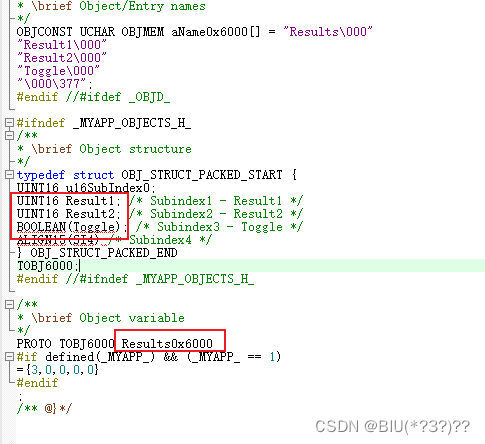
- myappObjects.h:自定义的变量在该文件中,包括0x1600、0x1700、0x1C12、0x6000、0x7000等所有数据。自定义的变量数组为 名称+地址,如Results0x6000。单个变量即为变量名,如Result1 。
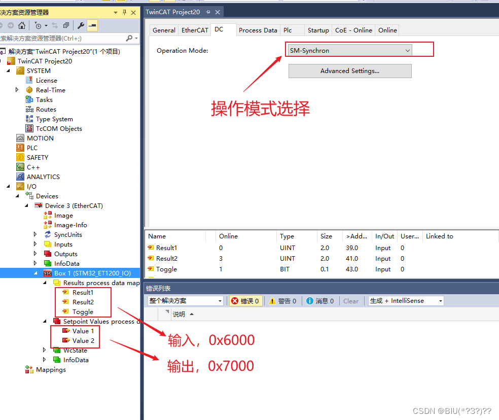
主站操作:VS2015 + Twincat3
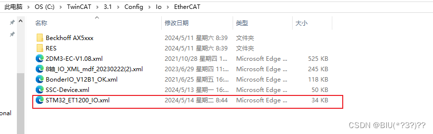
- 生成的xml文件放入指定目录 C:\TwinCAT\3.1\Config\Io\EtherCAT
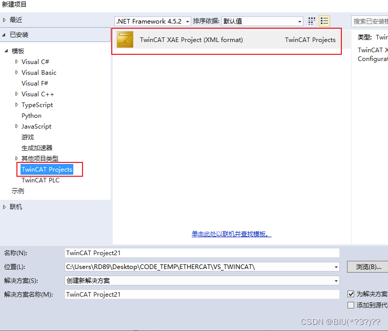
- VS2015新建项目
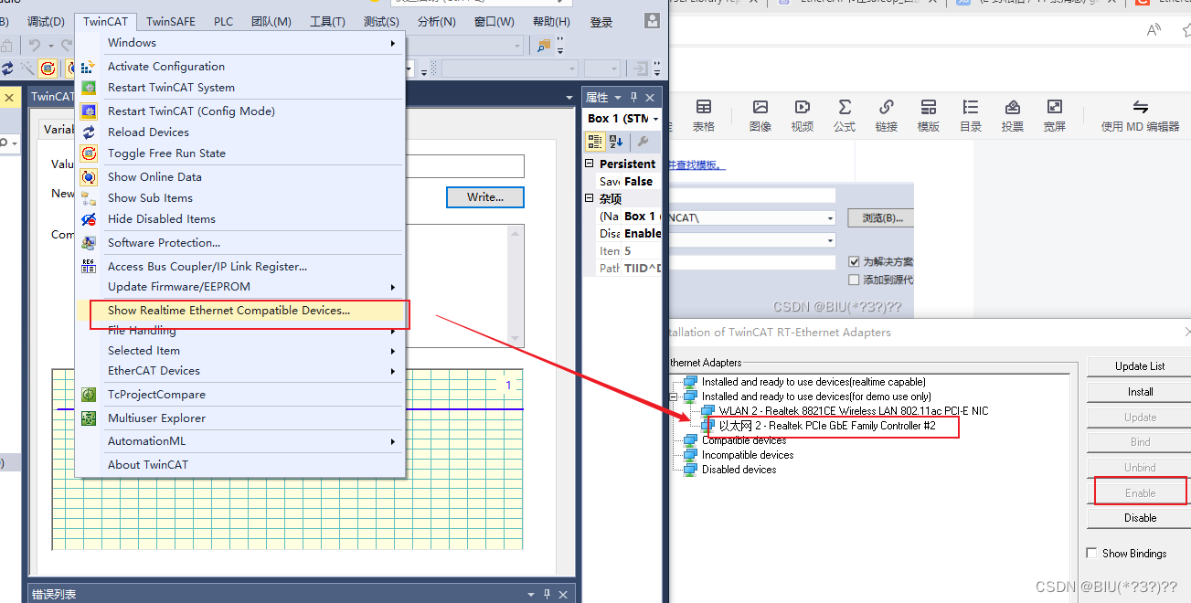
- 安装网卡
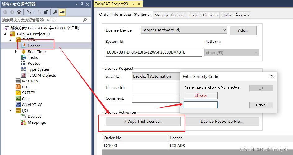
- 获取许可
- 扫描设备,会按顺序跳提示框,一直确定

- 扫描成功界面
- 切换到OP状态
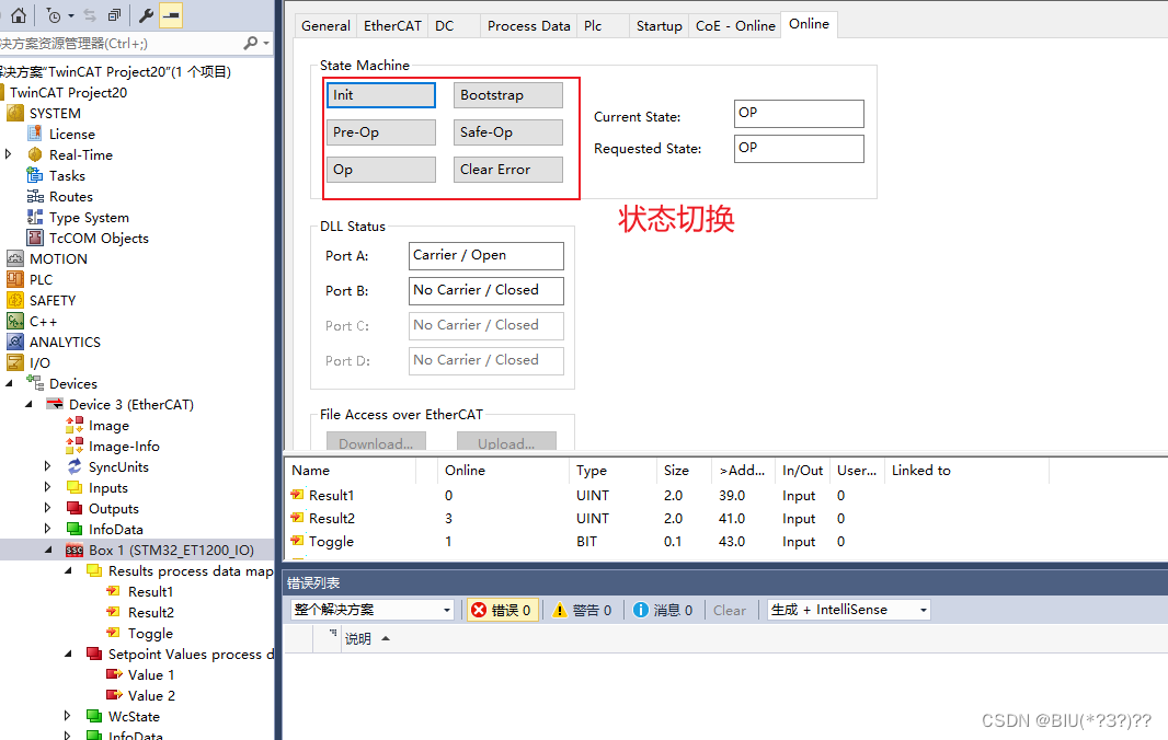
- 查看初始值,没有任何问题,通讯很成功
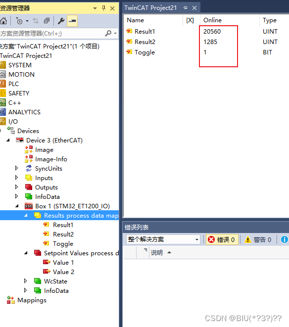
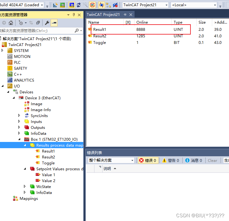
- 往Value写入数值
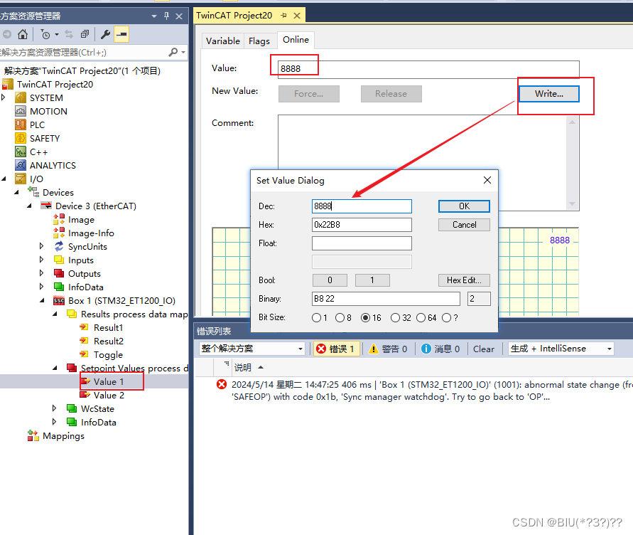
- Result也变为相应数值
如果要增加变量,需要修改以下文件:
- xml文件修改,对0x6000/0x7000、0x1600/0x1A00、0x1C12/0X1C13 同时进行修改(注意字节对齐,地址需为n * 16bit)
- myappObjects.h 修改,对应xml文件的修改,相应修改变量定义(如果没有对应上,通讯可能失败)
- myapp.c 修改,对PDO数据传输函数进行修改,增加数据传输
还是比较麻烦,也容易漏改,还是用SSC重新生成比较快,然后再替换el9800hw.c,el9800hw.h,再修改myapp.c就好了,这样的变量定义是自动生成的,不会出现对应不上的问题。
本文属于学习笔记,其中多是个人理解,可能多有偏差,仅供学习记录,不专业的地方还望指正。


 7457
7457


 被折叠的 条评论
为什么被折叠?
被折叠的 条评论
为什么被折叠?
 到【灌水乐园】发言


