


六自由度机械手正逆运动学
1 正运动学
正向运动学已知条件为各个关节的角度,通过各个关节的角度来求解机械手末端的位姿。
1.1 DH法参数表

按如上步骤对六自由度机械手建立坐标系,得到如图:

根据所建立的坐标系采用Denavit-Hartenbery法进行运动学求解,其连杆参数如下表所示。

令l1=50cm,l2=l3=40cm,l4=20cm,l5=l6=0cm。
1.2 建立运动学方程
变换矩阵的运算可以利用matlab中的符号变量syms,以坐标系4对坐标系3的坐标变换为例:
%坐标系4对坐标系3的坐标变换
syms c4 s4 l4;
T1=[1 0 0 0;
     0 0 -1 0;
     0 1 0 0;
     0 0 0 1];
T2=[c4 -s4 0 0;
     s4 c4 0 0 ;
     0 0 1 0;
     0 0 0 1];
T3=[1 0 0 0;
     0 1 0 0;
     0 0 1 l4;
     0 0 0 1];
T34=T1*T2*T3

%得到答案
T34 =

[ c4, -s4,  0,   0]
[  0,   0, -1, -l4]
[ s4,  c4,  0,   0]
[  0,   0,  0,   1]
可以得出各个变换矩阵,也可通过手动计算的方式,得到变换矩阵:

由此可得:

计算可得:


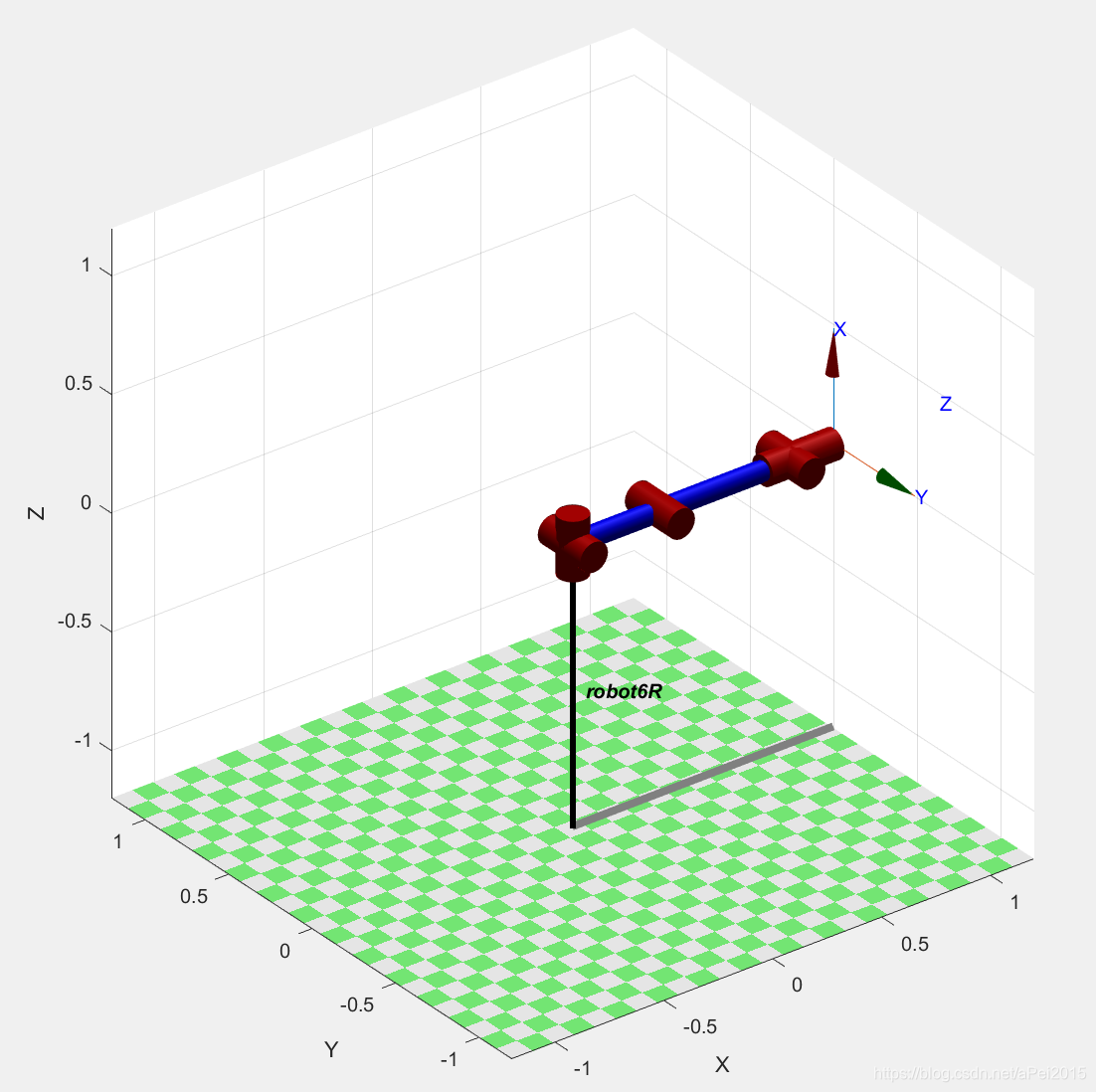
1.3 Matlab建模
根据所得的DH参数表,再利用matlab机器人工具箱robotic toolbox,可以很简便的得到matlab模型,matlab程序如下:
clear all
clc
%The parameter of DH
l=[0.5 0.4 0.4 0.2 0.2 0.2 0.2]
a=pi/2
%MDH coordinate
% θ d a α offset
L(1)=Link([0 0 0 0 0 ],'modified');
L(2)=Link([0 0 0 a 0 ],'modified');
L(3)=Link([0 0 l(2) 0 0 ],'modified');
L(4)=Link([0 l(3)+l(4) 0 a 0 ],'modified');
L(5)=Link([0 0 0 -a 0 ],'modified');
L(6)=Link([0 l(5) 0 a 0 ],'modified');
%L(7)=Link([0 l(6) 0 0 0 ],'modified');
qr=[0 0 pi/2 0 0 0 ] ; % ready
qu=[0 pi/3 -pi/6 0 pi/3 0 ];
%qu=[0 0 0 0 0 0 0];% standup
robot=SerialLink(L,'name','robot6R','manufacturer','Unimation','comment','AK&B');
robot.display(); %display MDH table
robot.fkine(qr) %zero
robot.plot(qr); %ready
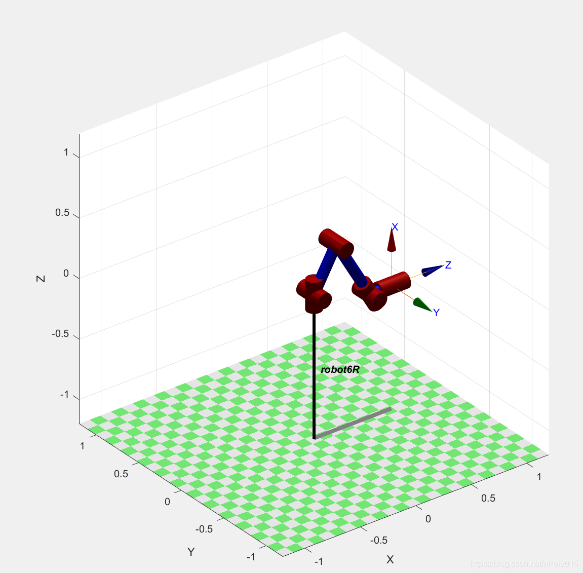
robot.fkine(qu);
robot.plot(qu); %standup
t=0:0.01:1;
[q,qd,qdd]=jtraj(qr,qu,t);
plot(t,qd,t,qdd);
teach(robot)
得到结果:
l =

    0.5000    0.4000    0.4000    0.2000    0.2000    0.2000    0.2000


a =

    1.5708


robot =

robot6R [Unimation]:: 6 axis, RRRRRR, modDH, slowRNE
 - AK&B;
+---+-----------+-----------+-----------+-----------+-----------+
| j |     theta |         d |         a |     alpha |    offset |
+---+-----------+-----------+-----------+-----------+-----------+
|  1|         q1|          0|          0|          0|          0|
|  2|         q2|          0|          0|     1.5708|          0|
|  3|         q3|          0|        0.4|          0|          0|
|  4|         q4|        0.6|          0|     1.5708|          0|
|  5|         q5|          0|          0|    -1.5708|          0|
|  6|         q6|        0.2|          0|     1.5708|          0|
+---+-----------+-----------+-----------+-----------+-----------+


ans =
         0         0         1       1.2
         0        -1         0         0
         1         0         0         0
         0         0         0         1
以及:
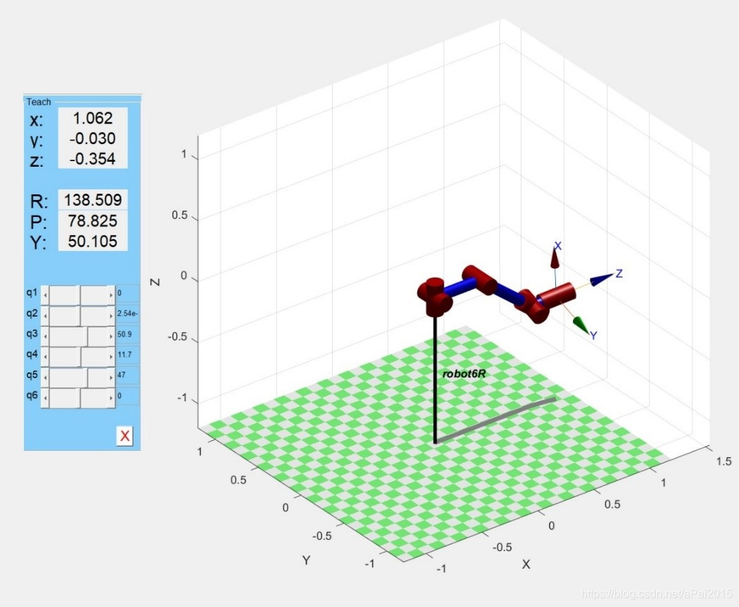
再最后的teach——示教图中,可以通过改变关节角度来实现对机器人运动的控制。
2 逆运动学
逆运动学分析与正运动学分析计算过程完全相反,即给出驱动机器人末端位姿,求解各个连杆关节的变量值。

可以得到


可以算出各个关节的选择角度。
3 工作空间
机械手的工作空间,可通过一下matlab程序得出:
clc
clear all
%DH参数
l=[0.5 0.4 0.4 0.2 0.2 0.2 0.2]
a=pi/2
%       theta    d        a        alpha     offset
L1=Link([0   0        0    0          0  ],'modified');
L2=Link([0   0        0    a          0  ],'modified');
L3=Link([0   0       l(2)    0          0  ],'modified');
L4=Link([0   l(3)+l(4)    0    a          0  ],'modified');
L5=Link([0   0        0   -a          0  ],'modified');
L6=Link([0   l(5)       0    a          0  ],'modified');
robot=SerialLink([L1 L2 L3 L4 L5 L6 ],'name','manman');
A=unifrnd(-pi,pi/2,[1,30000]);
B=unifrnd(-pi/2,pi/2,[1,30000]);
C=unifrnd(-pi,pi,[1,30000]);
D=unifrnd(-pi,pi/2,[1,30000]);
E=unifrnd(-pi/2,pi/2,[1,30000]);
F=unifrnd(-pi,pi,[1,30000]);

G= cell(30000, 3);		%建立元胞数组
for n = 1:30000
    G{n} =[A(n) B(n) C(n) D(n) E(n) F(n)];
end                        	%产生3000组随机点
H1=cell2mat(G);              %将元胞数组转化为矩阵
T=double(robot.fkine(H1));      %机械臂正解
figure(1)
scatter3(squeeze(T(1,4,:)),squeeze(T(2,4,:)),squeeze(T(3,4,:)))
robot.plot([pi/2 pi/4 0],'workspace',[-5 5 -5 5 -5 5 ],'tilesize',2)		%机械臂图
得到下图:


 3万+
3万+

 被折叠的 条评论
为什么被折叠?
被折叠的 条评论
为什么被折叠?
 到【灌水乐园】发言


