


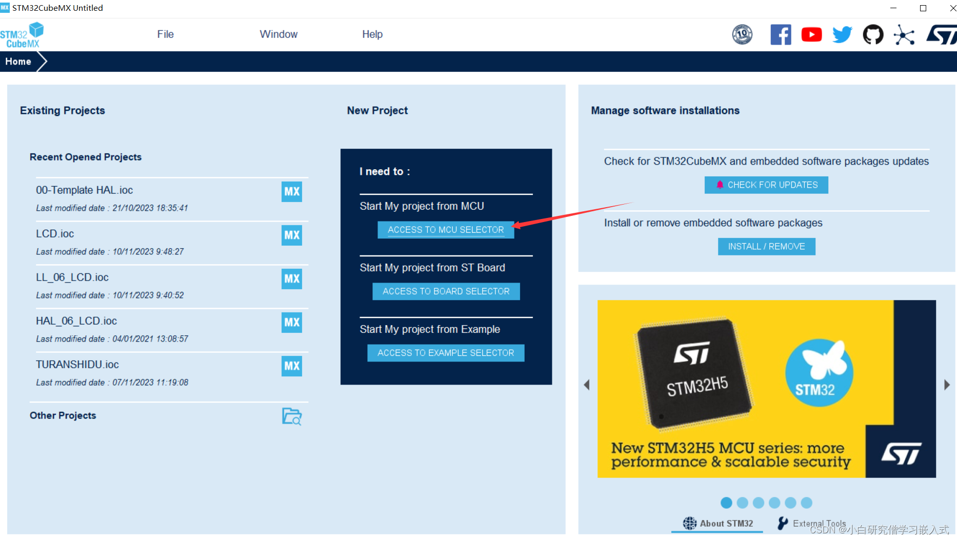
本次选用的单片机型号是STM32F103C8T6最小系统,也是淘宝上就轻便的那一款。
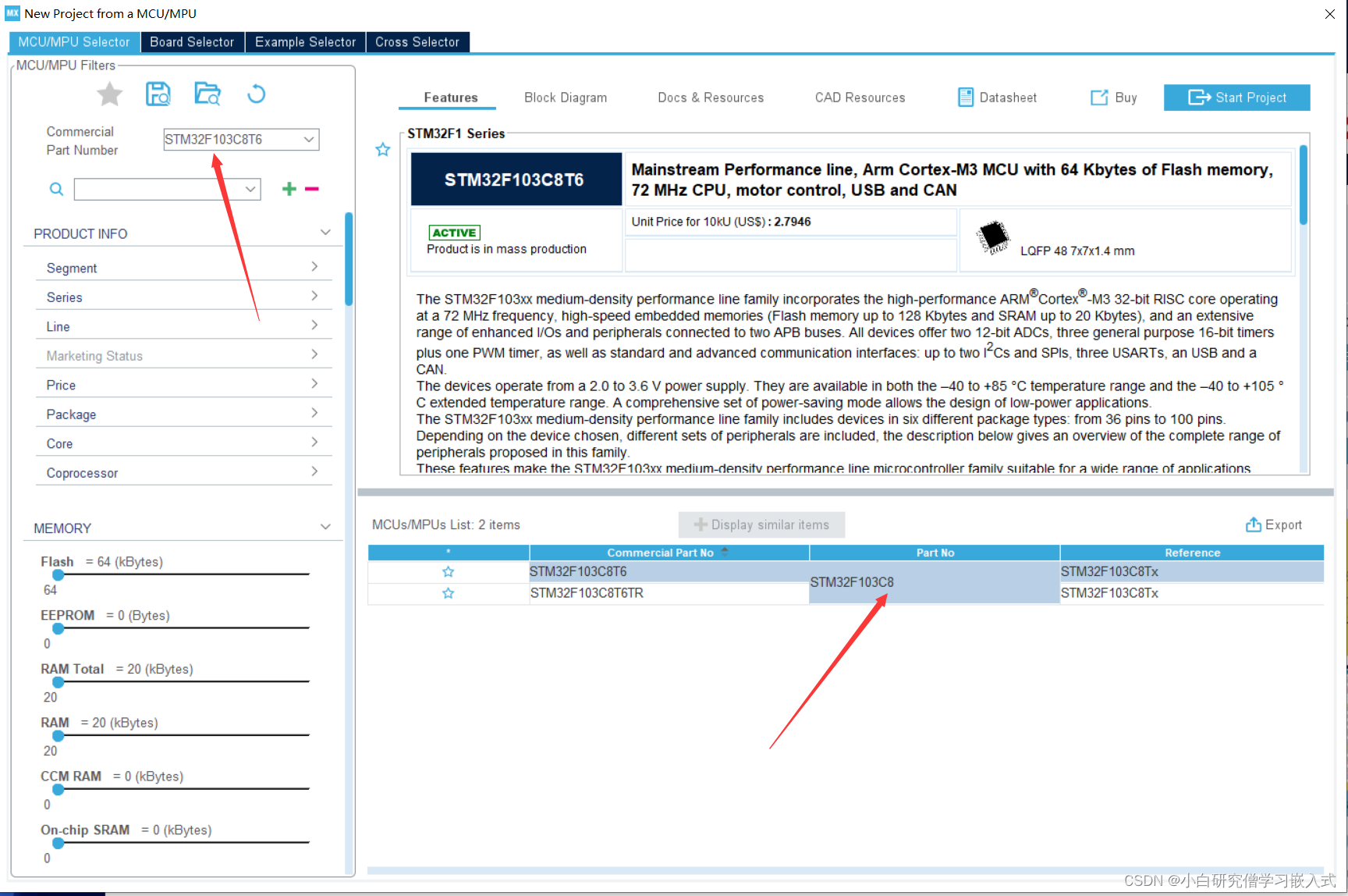
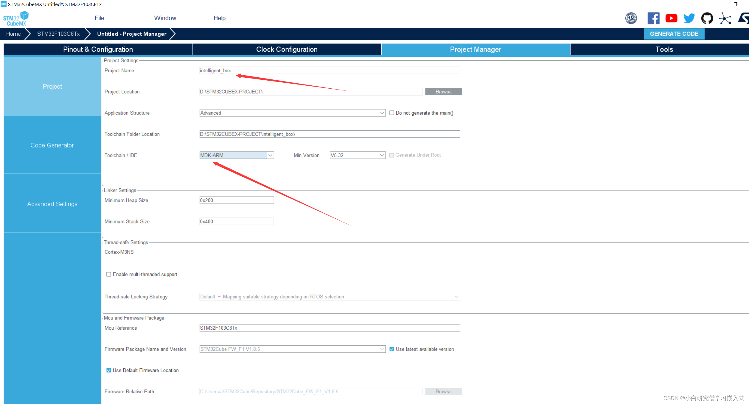
首先打开STM32CUBEMX新建一个工程,看图如下:
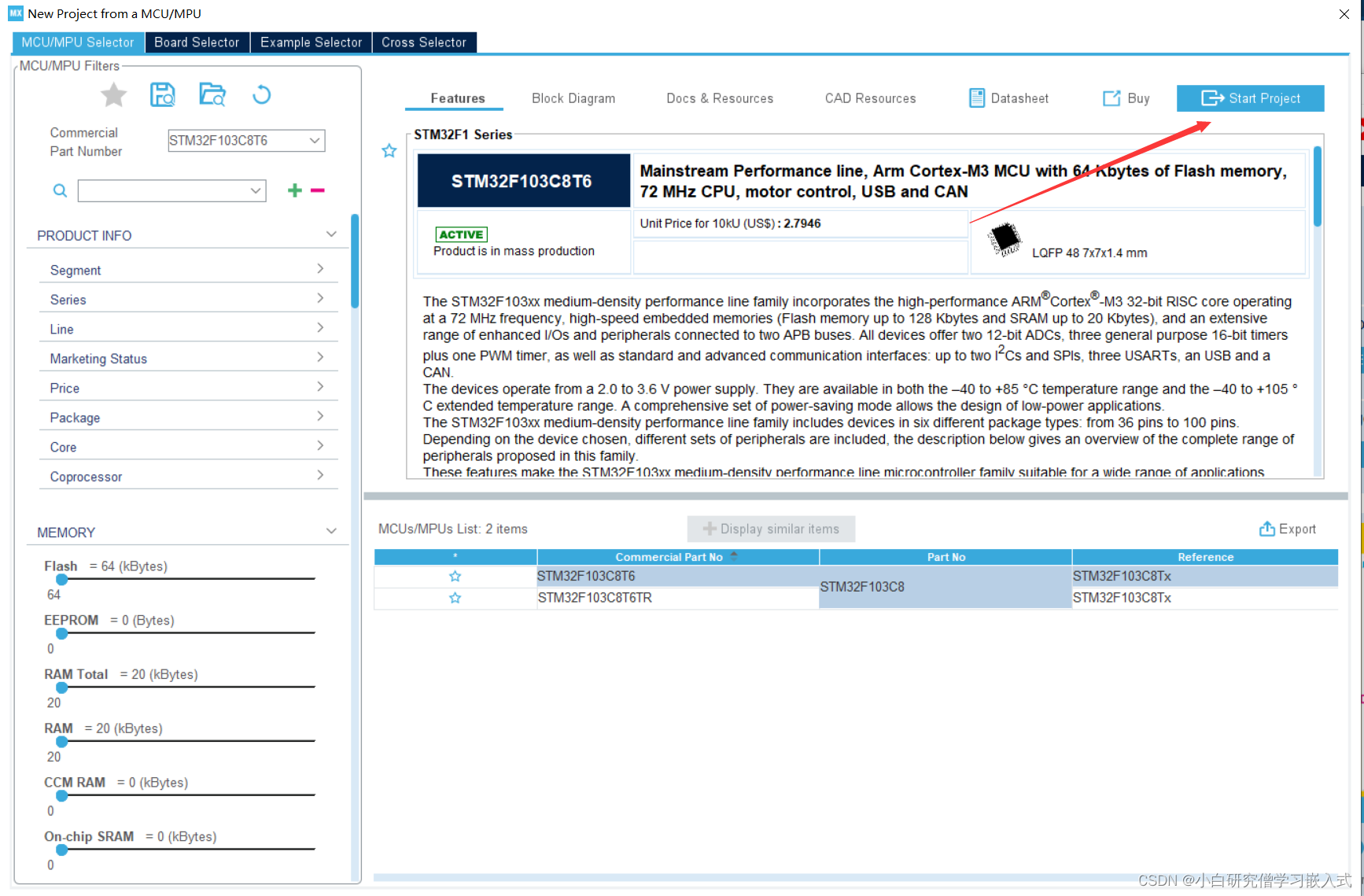
到此我们就创建完成了工程,接下来需要配置引脚和时钟完成基本的32配置。
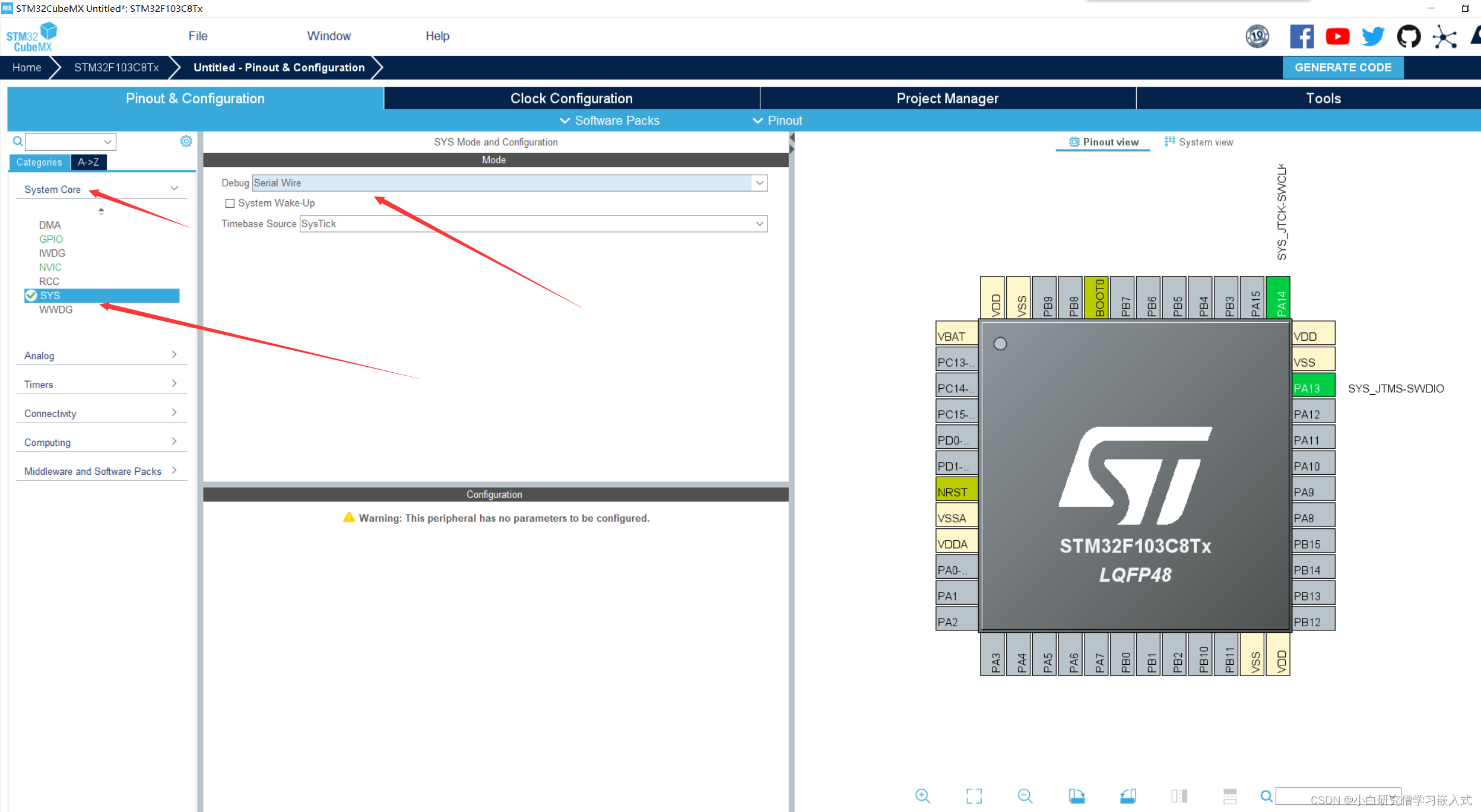
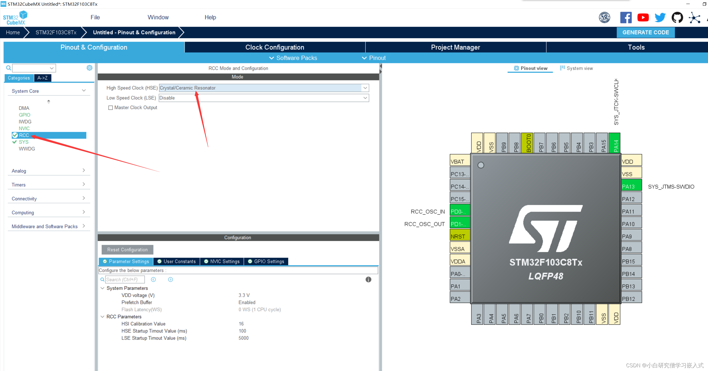
像上图配置,开启调试引脚,由于这款最小系统板没有设计串口模块,所以后头我们需要使用ST-LINKV2进行程序烧录,如果有串口模块也可以使用串口模块进行程序烧录。
接下来就是开启时钟,选用的是外部的8Mhz晶振作为时钟。
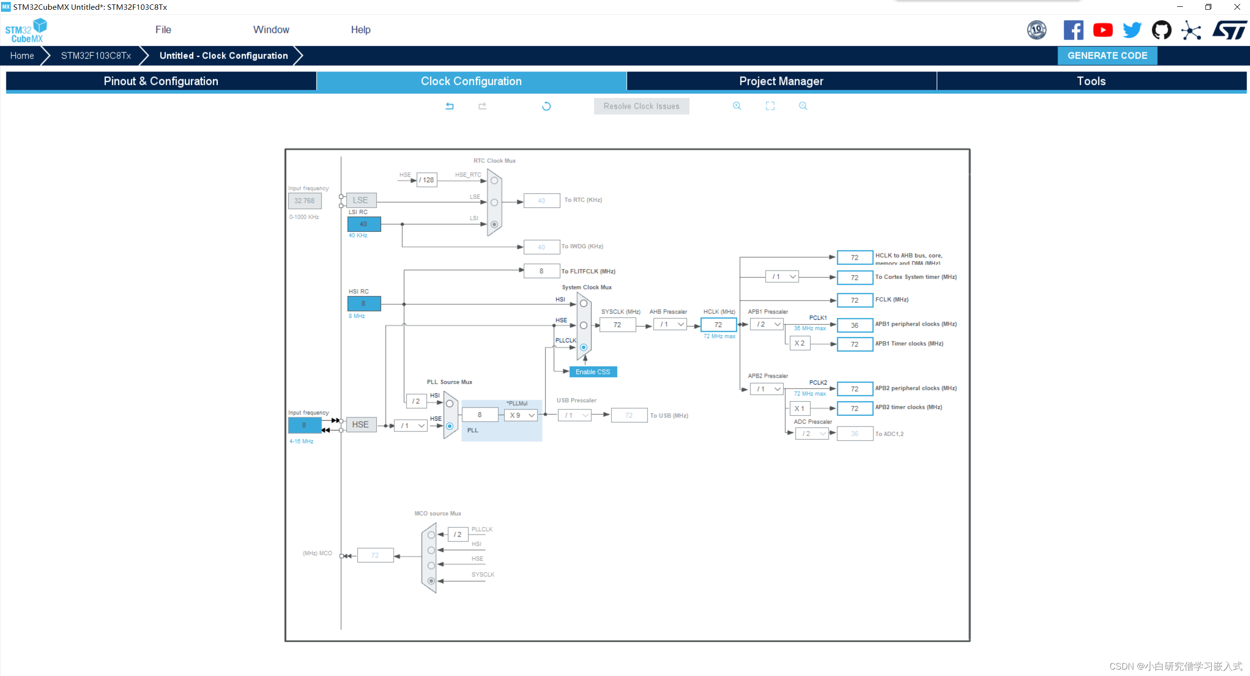
开启完晶振后,我们需要下一步配置时钟树,此处配置72Mhz工作,下面的PWM输出也是结合这个频率计算,时钟树的配置如下。
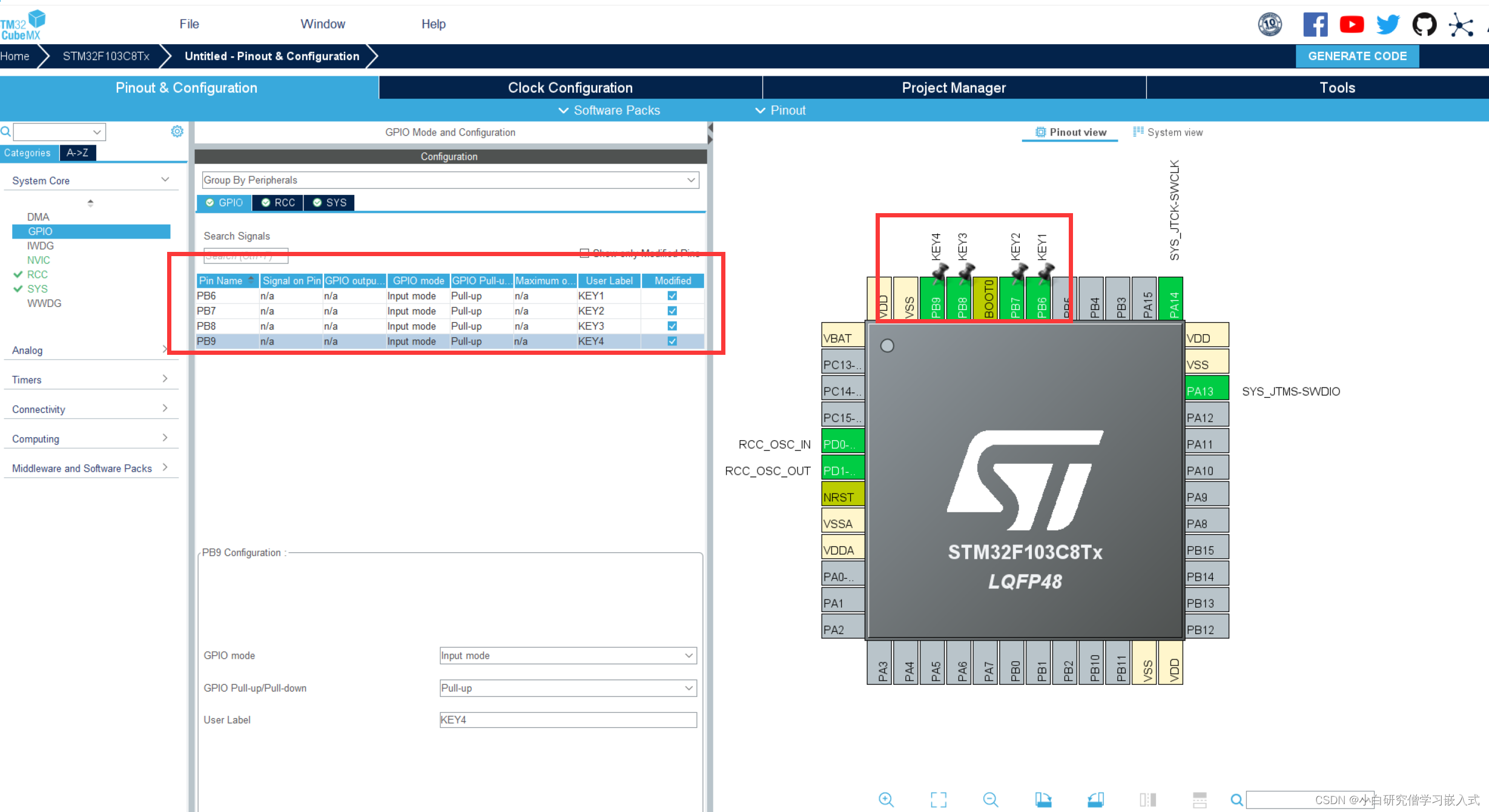
那么接下来是要进行GPIO口和PWM模式的配置,此处选用4个舵机和4个按键进行控制,配置和控制的原理一致,大家可以结合自己设计的电路和原理图分析映射到对应的引脚配置即可。
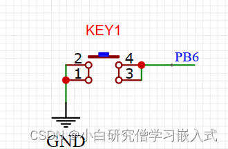
首先按键的电路设计采用是一端接地,另一端接IO的形式,只需要将IO口配置成输入模式,读取引脚的电平即可判断按键是否按下,由于此处一端已经接地了,我们需要将IO口配置成输入上拉模式,让他初始读取电平保持高电平,这样子按键按下后就接通地读取到低电平。如果自己的开发板是一端接IO口,另外一端接VCC,此处就需要考虑设置成下拉输入。
此次我用到4个按键,分别是PB6、PB7、PB8、PB9,下面以PB6为例进行配置;
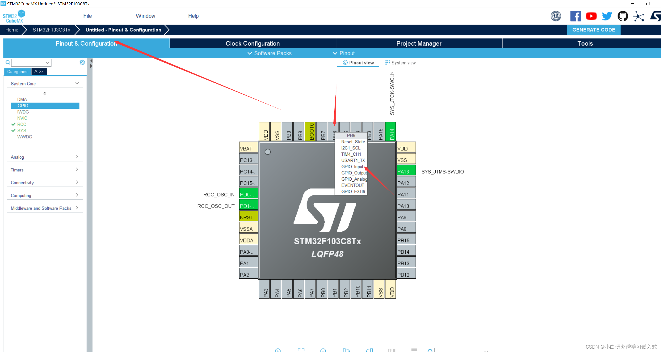

还可以在下图中对引脚重命名,方便程序调用,例如我命名PB6为KEY1

下图为4个完成配置的图片,根据自己的电路配置完成即可。
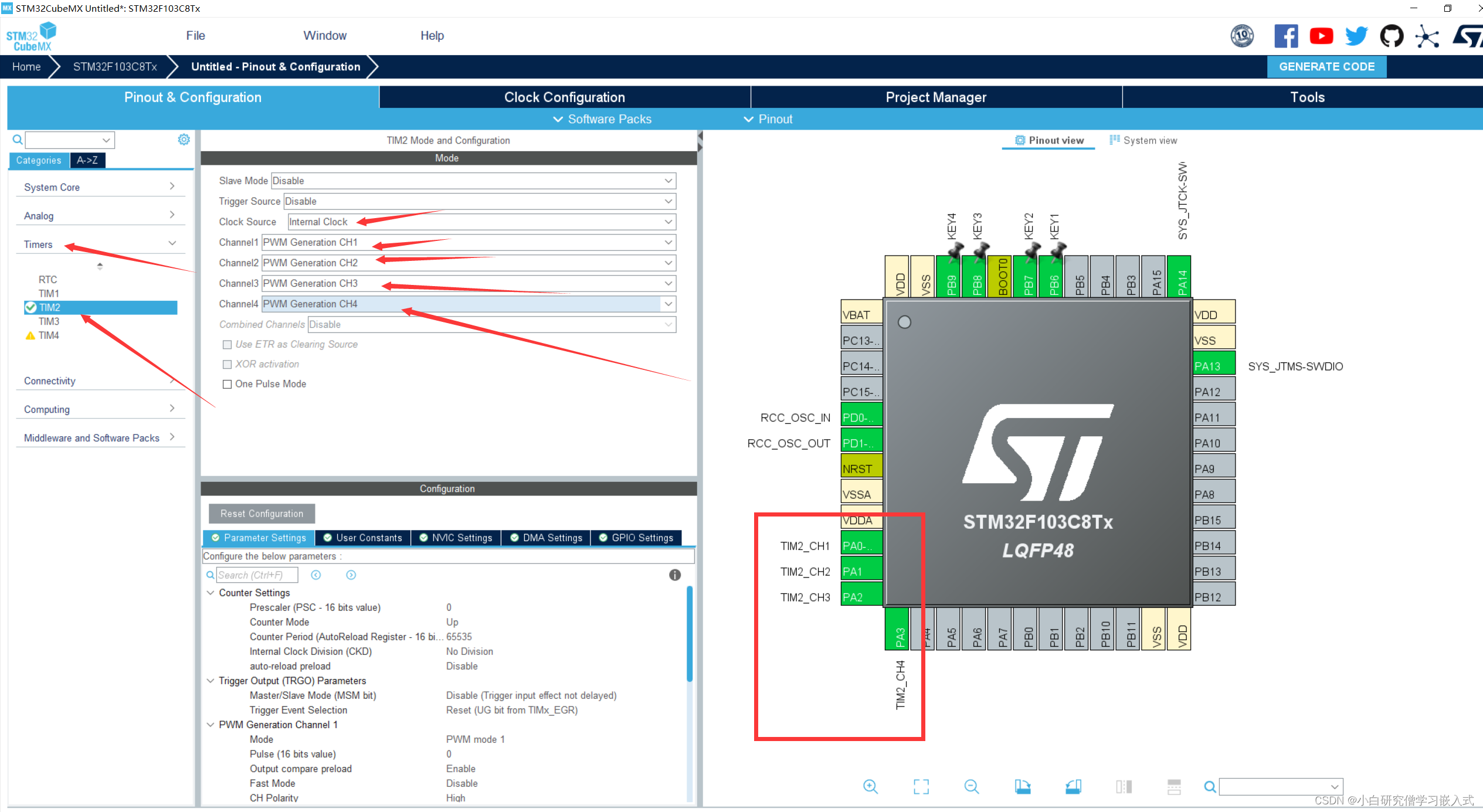
本小节的任务是完成按键控制舵机任务,使用一个按键控制一个舵机,那么接下来需要对舵机的PWM进行配置,本次选用的4个舵机IO口为PA0,PA1,PA2,PA3。下面会以PA0举例配置,其余几个依次类推接口。
现在市面常见的舵机控制均使用PWM,需要使用的是20ms周期的波形,占空比为0.5ms-2.5ms,映射过去对应0-180°,此处选用的舵机型号是SG90小小的蓝色舵机,具体的原理和细节可以看其它博主的描述,很详细的,此处不再赘述。
下图为开启PWM通道的设置,它们均是定时器2的通道,所以我这里一起开了,如果使用其它引脚只需要打开IO口对应映射定时器的PWM通道即可。
那么20ms其实对应的是50hz波形,我们需要计算分频系数和,定时器计数值来得到50hz周期波形。
此处设置PSC分频系数为719(720-1),计数值为1999(2000-1)
72000000/720=100000hz
100000/2000=50hz
如下图即可:
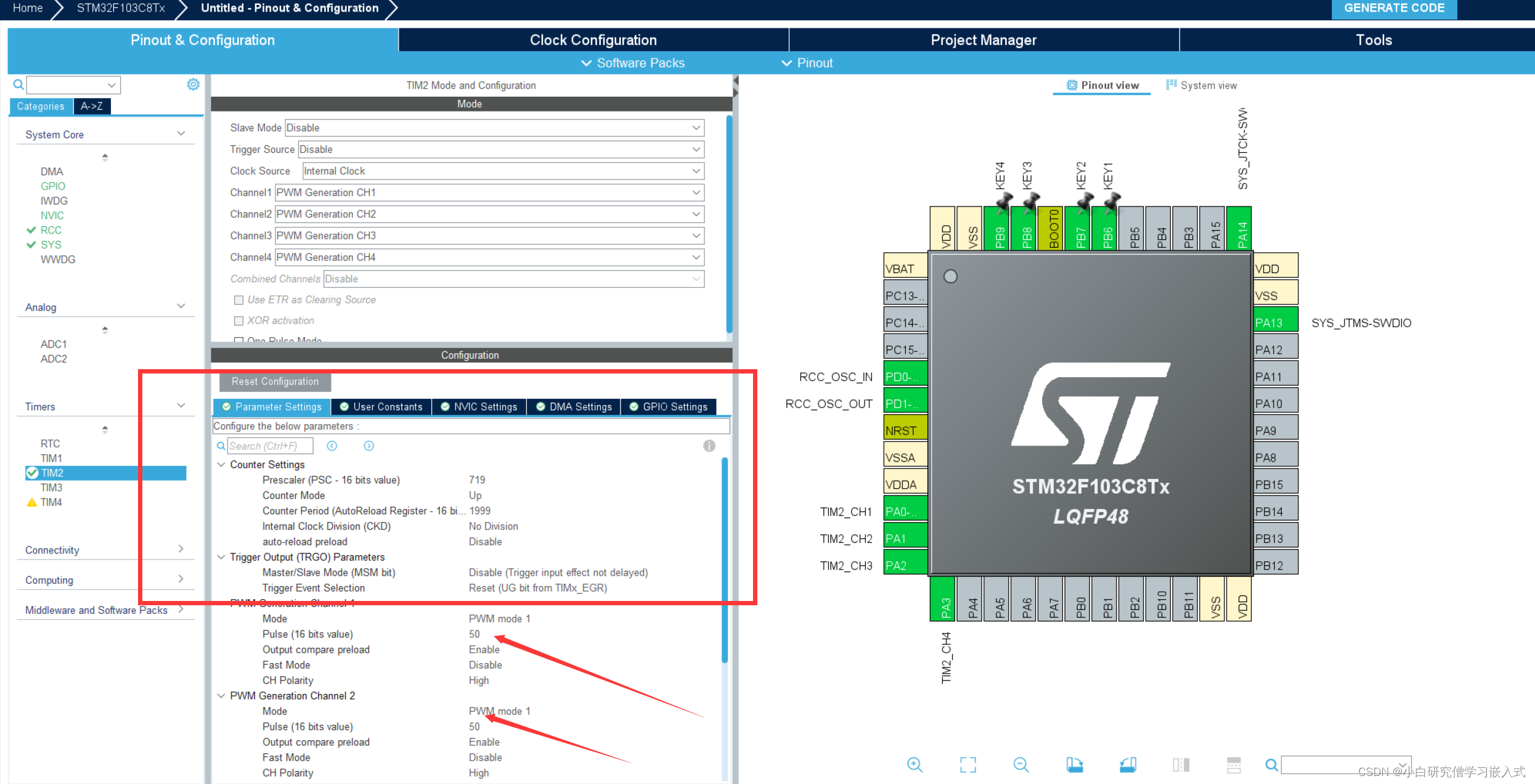
上面的脉冲值我们设置为50,默认初始化后舵机在0°位置,因为2000对应20ms,那么50对应0.5ms刚好是0°位置,比较重要的一步是不能忘记开启定时器中断,如下所示
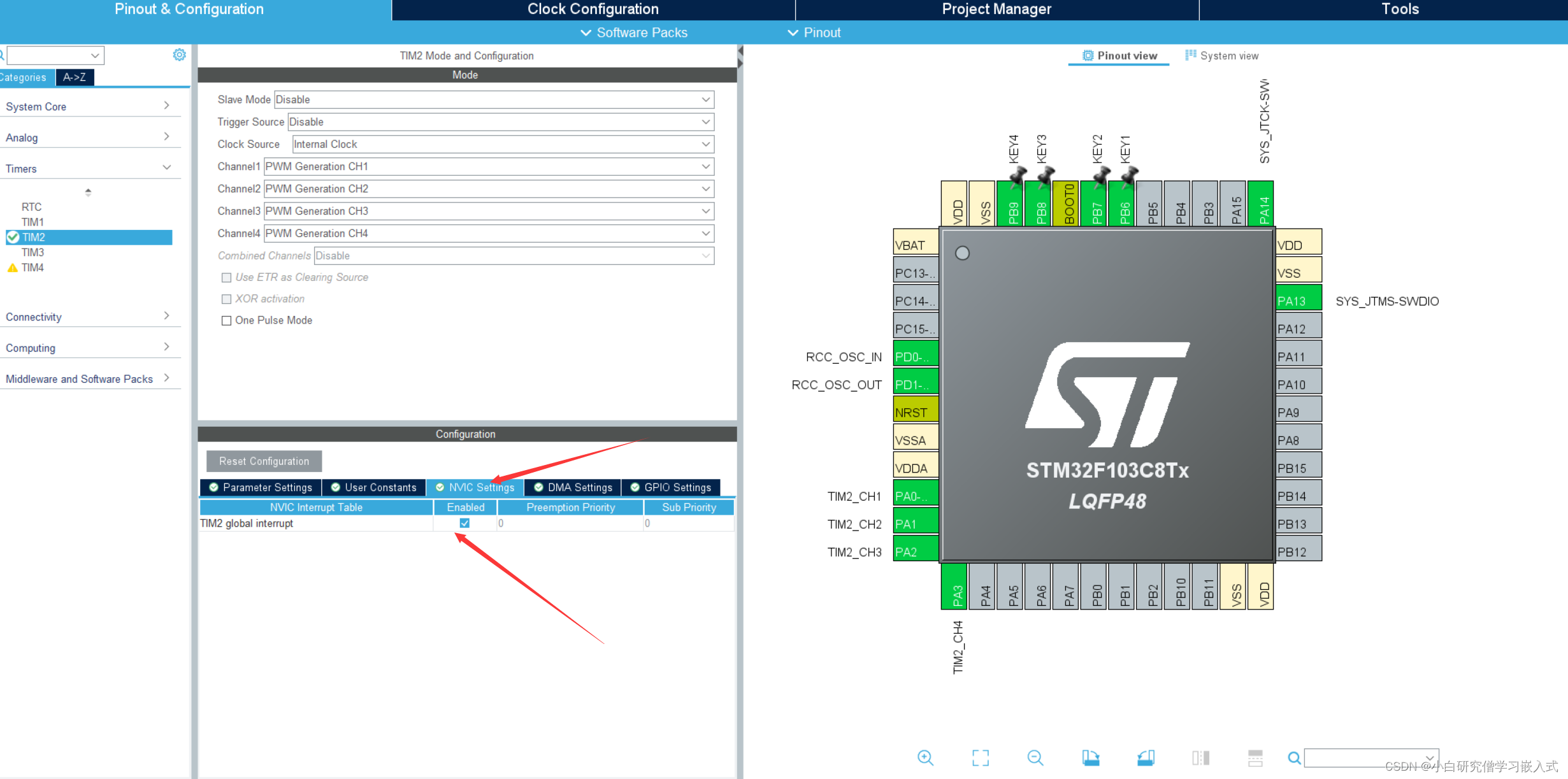
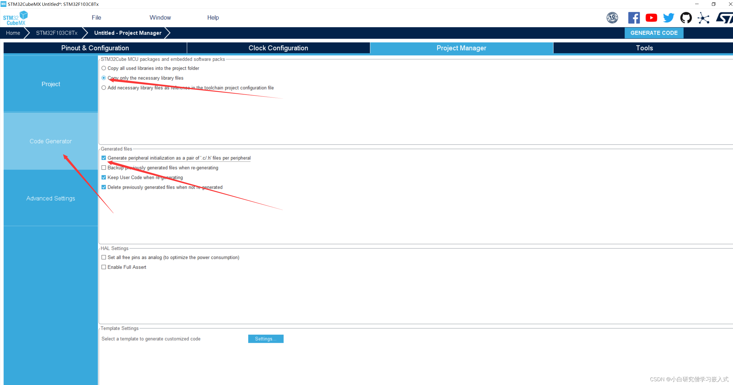
完成最后几步配置输出keil5工程
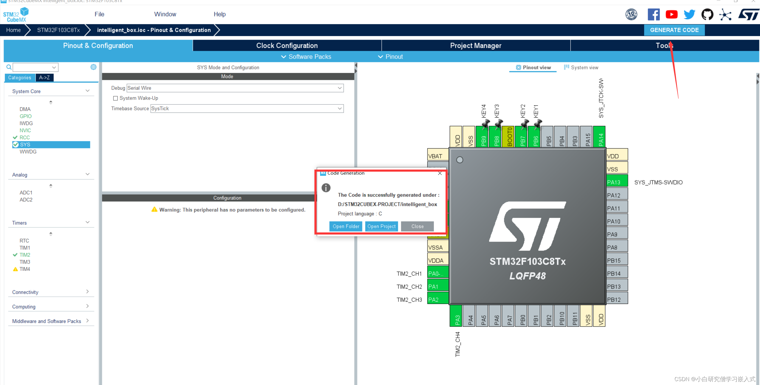
点击右上角生成,如下图就生成工程成功。
下面就是程序书写部分,4个按键4个舵机,写一个1对1按键控制舵机程序。
main.c代码
/* USER CODE BEGIN Header */
/**
  ******************************************************************************
  * @file           : main.c
  * @brief          : Main program body
  ******************************************************************************
  * @attention
  *
  * Copyright (c) 2023 STMicroelectronics.
  * All rights reserved.
  *
  * This software is licensed under terms that can be found in the LICENSE file
  * in the root directory of this software component.
  * If no LICENSE file comes with this software, it is provided AS-IS.
  *
  ******************************************************************************
  */
/* USER CODE END Header */
/* Includes ------------------------------------------------------------------*/
#include "main.h"
#include "tim.h"
#include "gpio.h"

/* Private includes ----------------------------------------------------------*/
/* USER CODE BEGIN Includes */

/* USER CODE END Includes */

/* Private typedef -----------------------------------------------------------*/
/* USER CODE BEGIN PTD */

/* USER CODE END PTD */

/* Private define ------------------------------------------------------------*/
/* USER CODE BEGIN PD */

/* USER CODE END PD */

/* Private macro -------------------------------------------------------------*/
/* USER CODE BEGIN PM */

/* USER CODE END PM */

/* Private variables ---------------------------------------------------------*/

/* USER CODE BEGIN PV */

/* USER CODE END PV */

/* Private function prototypes -----------------------------------------------*/
void SystemClock_Config(void);
/* USER CODE BEGIN PFP */

/* USER CODE END PFP */

/* Private user code ---------------------------------------------------------*/
/* USER CODE BEGIN 0 */

/* USER CODE END 0 */

/**
  * @brief  The application entry point.
  * @retval int
  */
int main(void)
{
  /* USER CODE BEGIN 1 */
	uint8_t key_val;
	static _Bool s1=0,s2=0,s3=0,s4=0;//表示4个舵机状态
	uint8_t state=1;
  /* USER CODE END 1 */

  /* MCU Configuration--------------------------------------------------------*/

  /* Reset of all peripherals, Initializes the Flash interface and the Systick. */
  HAL_Init();

  /* USER CODE BEGIN Init */

  /* USER CODE END Init */

  /* Configure the system clock */
  SystemClock_Config();

  /* USER CODE BEGIN SysInit */

  /* USER CODE END SysInit */

  /* Initialize all configured peripherals */
  MX_GPIO_Init();
  MX_TIM2_Init();
  /* USER CODE BEGIN 2 */
	HAL_TIM_Base_Start(&htim2);
	HAL_TIM_PWM_Start(&htim2,TIM_CHANNEL_1);
	HAL_TIM_PWM_Start(&htim2,TIM_CHANNEL_2);
	HAL_TIM_PWM_Start(&htim2,TIM_CHANNEL_3);
	HAL_TIM_PWM_Start(&htim2,TIM_CHANNEL_4);
  /* USER CODE END 2 */

  /* Infinite loop */
  /* USER CODE BEGIN WHILE */
  while (1)
  {
		key_val = KEY_Scan(0);
		if(key_val==1)
		{
			if(state==1)
			{
				state=0;
				s1=!s1;
			}
			if(s1==0)TIM2->CCR4=50;
			if(s1==1)TIM2->CCR4=150;
		}
		else if(key_val==2)
		{
			if(state==1)
			{
				state=0;
				s2=!s2;
			}
			if(s2==0)TIM2->CCR3=50;
			if(s2==1)TIM2->CCR3=150;
		}
		else if(key_val==3)
		{
			if(state==1)
			{
				state=0;
				s3=!s3;
			}
			if(s3==0)TIM2->CCR2=50;
			if(s3==1)TIM2->CCR2=150;
		}
		else if(key_val==4)
		{
			if(state==1)
			{
				state=0;
				s4=!s4;
			}
			if(s4==0)TIM2->CCR1=50;
			if(s4==1)TIM2->CCR1=150;
		}
		else if(key_val==0)
		{
			state=1;
		}

    /* USER CODE END WHILE */

    /* USER CODE BEGIN 3 */
  }
  /* USER CODE END 3 */
}

/**
  * @brief System Clock Configuration
  * @retval None
  */
void SystemClock_Config(void)
{
  RCC_OscInitTypeDef RCC_OscInitStruct = {0};
  RCC_ClkInitTypeDef RCC_ClkInitStruct = {0};

  /** Initializes the RCC Oscillators according to the specified parameters
  * in the RCC_OscInitTypeDef structure.
  */
  RCC_OscInitStruct.OscillatorType = RCC_OSCILLATORTYPE_HSE;
  RCC_OscInitStruct.HSEState = RCC_HSE_ON;
  RCC_OscInitStruct.HSEPredivValue = RCC_HSE_PREDIV_DIV1;
  RCC_OscInitStruct.HSIState = RCC_HSI_ON;
  RCC_OscInitStruct.PLL.PLLState = RCC_PLL_ON;
  RCC_OscInitStruct.PLL.PLLSource = RCC_PLLSOURCE_HSE;
  RCC_OscInitStruct.PLL.PLLMUL = RCC_PLL_MUL9;
  if (HAL_RCC_OscConfig(&RCC_OscInitStruct) != HAL_OK)
  {
    Error_Handler();
  }

  /** Initializes the CPU, AHB and APB buses clocks
  */
  RCC_ClkInitStruct.ClockType = RCC_CLOCKTYPE_HCLK|RCC_CLOCKTYPE_SYSCLK
                              |RCC_CLOCKTYPE_PCLK1|RCC_CLOCKTYPE_PCLK2;
  RCC_ClkInitStruct.SYSCLKSource = RCC_SYSCLKSOURCE_PLLCLK;
  RCC_ClkInitStruct.AHBCLKDivider = RCC_SYSCLK_DIV1;
  RCC_ClkInitStruct.APB1CLKDivider = RCC_HCLK_DIV2;
  RCC_ClkInitStruct.APB2CLKDivider = RCC_HCLK_DIV1;

  if (HAL_RCC_ClockConfig(&RCC_ClkInitStruct, FLASH_LATENCY_2) != HAL_OK)
  {
    Error_Handler();
  }
}

/* USER CODE BEGIN 4 */

/* USER CODE END 4 */

/**
  * @brief  This function is executed in case of error occurrence.
  * @retval None
  */
void Error_Handler(void)
{
  /* USER CODE BEGIN Error_Handler_Debug */
  /* User can add his own implementation to report the HAL error return state */
  __disable_irq();
  while (1)
  {
  }
  /* USER CODE END Error_Handler_Debug */
}

#ifdef  USE_FULL_ASSERT
/**
  * @brief  Reports the name of the source file and the source line number
  *         where the assert_param error has occurred.
  * @param  file: pointer to the source file name
  * @param  line: assert_param error line source number
  * @retval None
  */
void assert_failed(uint8_t *file, uint32_t line)
{
  /* USER CODE BEGIN 6 */
  /* User can add his own implementation to report the file name and line number,
     ex: printf("Wrong parameters value: file %s on line %d\r\n", file, line) */
  /* USER CODE END 6 */
}
#endif /* USE_FULL_ASSERT */
gpio.c
/* USER CODE BEGIN Header */
/**
  ******************************************************************************
  * @file    gpio.c
  * @brief   This file provides code for the configuration
  *          of all used GPIO pins.
  ******************************************************************************
  * @attention
  *
  * Copyright (c) 2023 STMicroelectronics.
  * All rights reserved.
  *
  * This software is licensed under terms that can be found in the LICENSE file
  * in the root directory of this software component.
  * If no LICENSE file comes with this software, it is provided AS-IS.
  *
  ******************************************************************************
  */
/* USER CODE END Header */

/* Includes ------------------------------------------------------------------*/
#include "gpio.h"

/* USER CODE BEGIN 0 */

/* USER CODE END 0 */

/*----------------------------------------------------------------------------*/
/* Configure GPIO                                                             */
/*----------------------------------------------------------------------------*/
/* USER CODE BEGIN 1 */

/* USER CODE END 1 */

/** Configure pins as
        * Analog
        * Input
        * Output
        * EVENT_OUT
        * EXTI
*/
void MX_GPIO_Init(void)
{

  GPIO_InitTypeDef GPIO_InitStruct = {0};

  /* GPIO Ports Clock Enable */
  __HAL_RCC_GPIOD_CLK_ENABLE();
  __HAL_RCC_GPIOA_CLK_ENABLE();
  __HAL_RCC_GPIOB_CLK_ENABLE();

  /*Configure GPIO pins : PBPin PBPin PBPin PBPin */
  GPIO_InitStruct.Pin = KEY1_Pin|KEY2_Pin|KEY3_Pin|KEY4_Pin;
  GPIO_InitStruct.Mode = GPIO_MODE_INPUT;
  GPIO_InitStruct.Pull = GPIO_PULLUP;
  HAL_GPIO_Init(GPIOB, &GPIO_InitStruct);

}

/* USER CODE BEGIN 2 */

uint8_t KEY_Scan(uint8_t mode)
{
	 static uint8_t key_up=1;
	 if(mode==1) key_up=1;//支持连续按
	 if(key_up==1&&(KEY1==0||KEY2==0||KEY3==0||KEY4==0))
	 {
			HAL_Delay(10);//延时,防抖
			key_up=0;//标记这次key已经按下
			if(KEY1==0)return 1;
			else if(KEY2==0)return 2;
			else if(KEY3==0)return 3;
			else if(KEY4==0)return 4;
		}else if(KEY1==1&&KEY2==1&&KEY3==1&&KEY4==1)key_up=1;
		return 0;
}

/* USER CODE END 2 */
gpio.h
/* USER CODE BEGIN Header */
/**
  ******************************************************************************
  * @file    gpio.h
  * @brief   This file contains all the function prototypes for
  *          the gpio.c file
  ******************************************************************************
  * @attention
  *
  * Copyright (c) 2023 STMicroelectronics.
  * All rights reserved.
  *
  * This software is licensed under terms that can be found in the LICENSE file
  * in the root directory of this software component.
  * If no LICENSE file comes with this software, it is provided AS-IS.
  *
  ******************************************************************************
  */
/* USER CODE END Header */
/* Define to prevent recursive inclusion -------------------------------------*/
#ifndef __GPIO_H__
#define __GPIO_H__

#ifdef __cplusplus
extern "C" {
#endif

/* Includes ------------------------------------------------------------------*/
#include "main.h"

/* USER CODE BEGIN Includes */

/* USER CODE END Includes */

/* USER CODE BEGIN Private defines */
#define KEY1 HAL_GPIO_ReadPin(KEY1_GPIO_Port,KEY1_Pin)
#define KEY2 HAL_GPIO_ReadPin(KEY2_GPIO_Port,KEY2_Pin)
#define KEY3 HAL_GPIO_ReadPin(KEY3_GPIO_Port,KEY3_Pin)
#define KEY4 HAL_GPIO_ReadPin(KEY4_GPIO_Port,KEY4_Pin)
/* USER CODE END Private defines */

void MX_GPIO_Init(void);

/* USER CODE BEGIN Prototypes */
uint8_t KEY_Scan(uint8_t mode);
/* USER CODE END Prototypes */

#ifdef __cplusplus
}
#endif
#endif /*__ GPIO_H__ */
main.h
/* USER CODE BEGIN Header */
/**
  ******************************************************************************
  * @file           : main.h
  * @brief          : Header for main.c file.
  *                   This file contains the common defines of the application.
  ******************************************************************************
  * @attention
  *
  * Copyright (c) 2023 STMicroelectronics.
  * All rights reserved.
  *
  * This software is licensed under terms that can be found in the LICENSE file
  * in the root directory of this software component.
  * If no LICENSE file comes with this software, it is provided AS-IS.
  *
  ******************************************************************************
  */
/* USER CODE END Header */

/* Define to prevent recursive inclusion -------------------------------------*/
#ifndef __MAIN_H
#define __MAIN_H

#ifdef __cplusplus
extern "C" {
#endif

/* Includes ------------------------------------------------------------------*/
#include "stm32f1xx_hal.h"

/* Private includes ----------------------------------------------------------*/
/* USER CODE BEGIN Includes */

/* USER CODE END Includes */

/* Exported types ------------------------------------------------------------*/
/* USER CODE BEGIN ET */

/* USER CODE END ET */

/* Exported constants --------------------------------------------------------*/
/* USER CODE BEGIN EC */

/* USER CODE END EC */

/* Exported macro ------------------------------------------------------------*/
/* USER CODE BEGIN EM */

/* USER CODE END EM */

/* Exported functions prototypes ---------------------------------------------*/
void Error_Handler(void);

/* USER CODE BEGIN EFP */

/* USER CODE END EFP */

/* Private defines -----------------------------------------------------------*/
#define KEY1_Pin GPIO_PIN_6
#define KEY1_GPIO_Port GPIOB
#define KEY2_Pin GPIO_PIN_7
#define KEY2_GPIO_Port GPIOB
#define KEY3_Pin GPIO_PIN_8
#define KEY3_GPIO_Port GPIOB
#define KEY4_Pin GPIO_PIN_9
#define KEY4_GPIO_Port GPIOB

/* USER CODE BEGIN Private defines */

/* USER CODE END Private defines */

#ifdef __cplusplus
}
#endif

#endif /* __MAIN_H */
不懂得使用STLINKV2接线烧录的可以参考我的这篇文章
https://blog.csdn.net/anyi66622/article/details/130321309?spm=1001.2014.3001.5501


 1万+
1万+

 被折叠的 条评论
为什么被折叠?
被折叠的 条评论
为什么被折叠?
 到【灌水乐园】发言


