


书接上文
本章内容
熟悉一下ESP32S3的开发,修改范例程序的lvgl,使之能够匹配现在的显示屏。
具体工作大概为通过SPI接口连接一块SPI串口屏幕,并且适配lvgl,最后加上触摸屏作为输入。

屏幕
用了这块SPI屏幕,带触摸和SD卡插槽。下面有显示部分引脚功能说明

软件工程
工程有一个lvgl的demo程序,位于Espressif\frameworks\esp-idf-v4.4.3\examples\peripherals\lcd\lvgl路径下,不过默认是支持并口8080的方式进行显示的。
所以要改为SPI方式驱动,进行屏幕显示。原理很简单,开头加上屏幕初始化,显示的时候,将内容输入到显示屏即可。

相关重点
屏幕,触摸和移植。
屏幕驱动
代码参考Espressif\frameworks\esp-idf-v4.4.3\examples\peripherals\spi_master\lcd\main下面对于spi lcd的控制。
引脚配置如下
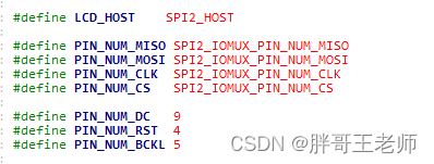
注意s3能用的spi有两个SPI2和SPI3,SPI2通常引脚固定,速度快,SPI3可以选择复用GPIO进行配置,速度稍慢,后面的触摸屏会用到。
屏幕SPI配置
屏幕驱动函数中,注意这里的配置
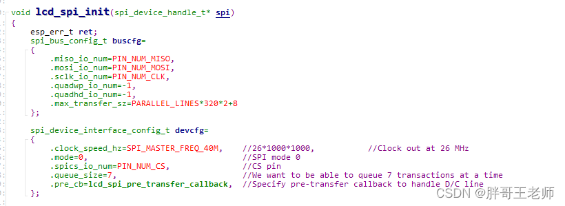
时钟频率可以选择最高到80Mhz,不过到了80M,我的屏幕就失真了,可能是屏幕自身不支持这么大的速率。

并行绘制
例子中注意这个宏定义,注释意思就是
为了加快传输速度,每个SPI传输都会发送一组显示的线。 此定义指定数量。更多意味着更多的内存使用,
但设置/完成传输的开销较小。确保240可以除以这个。
//To speed up transfers, every SPI transfer sends a bunch of lines. This define specifies how many. More means more memory use,
//but less overhead for setting up / finishing transfers. Make sure 240 is dividable by this.
#define PARALLEL_LINES 40
就是将一副图片,按照line的方式进行显示,每次传输40行数据。
众所周知,ili9341芯片,是支持直接写入显存的,大概意思就是,屏幕有一块显存,对应了每个像素点,通过2A和2B命令,配置好写入位置,
2A表示修改列范围

2B表示修改行范围
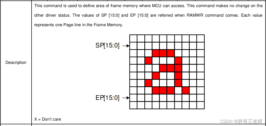
再执行2C命令,就可以直接写入显存数据了。
这个位置数据都是矩形,那么我们就可以以40行图像作为一个矩形,写入显存。
那么问题来了,既然有这么大的显存。那么我就要一帧一帧的数据写入可以吗?
答案是不可以,将PARALLEL_LINES调整超过50之后,就只能显示一部分画面了,因为SPI的一次传输,是有限制的
#define LCD_SPI_MAX_DATA_SIZE (SPI_LL_DATA_MAX_BIT_LEN / 8)
#define SPI_LL_DATA_MAX_BIT_LEN (1 << 18)
最多传输32768个字节,对于宽度320像素的屏幕,每行是320*2个字节,所以经过计算,每次最多传输
51行。
那么在小于51中,最大被240整除的数,那自然就是48了,所以设置为48,是效率最高的时候。

完整驱动
参考spi驱动lcd,将其封装为一个文件,对外提供一个初始化及绘图函数即可
/*
lcd_ili9341.c
  */

#include <stdio.h>
#include <stdlib.h>
#include <string.h>

#include "freertos/FreeRTOS.h"
#include "freertos/task.h"
#include "driver/gpio.h"
#include "driver/spi_master.h"
#include "esp_timer.h"
#include "esp_err.h"
#include "esp_log.h"
#include "esp_system.h"

static const char *TAG = "lcd_ili9341";


#define LCD_HOST    SPI2_HOST

#define PIN_NUM_MISO SPI2_IOMUX_PIN_NUM_MISO
#define PIN_NUM_MOSI SPI2_IOMUX_PIN_NUM_MOSI
#define PIN_NUM_CLK  SPI2_IOMUX_PIN_NUM_CLK
#define PIN_NUM_CS   SPI2_IOMUX_PIN_NUM_CS

#define PIN_NUM_DC   9
#define PIN_NUM_RST  4
#define PIN_NUM_BCKL 5

#define PARALLEL_LINES 48

/*
 The LCD needs a bunch of command/argument values to be initialized. They are stored in this struct.
*/
typedef struct
{
    uint8_t cmd;
    uint8_t data[16];
    uint8_t databytes; //No of data in data; bit 7 = delay after set; 0xFF = end of cmds.
} lcd_init_cmd_t;

typedef enum
{
    LCD_TYPE_ILI = 1,
    LCD_TYPE_ST,
    LCD_TYPE_MAX,
} type_lcd_t;

//Place data into DRAM. Constant data gets placed into DROM by default, which is not accessible by DMA.
DRAM_ATTR static const lcd_init_cmd_t st_init_cmds[]={
    /* Memory Data Access Control, MX=MV=1, MY=ML=MH=0, RGB=0 */
    {0x36, {(1<<5)|(1<<6)}, 1},
    /* Interface Pixel Format, 16bits/pixel for RGB/MCU interface */
    {0x3A, {0x55}, 1},
    /* Porch Setting */
    {0xB2, {0x0c, 0x0c, 0x00, 0x33, 0x33}, 5},
    /* Gate Control, Vgh=13.65V, Vgl=-10.43V */
    {0xB7, {0x45}, 1},
    /* VCOM Setting, VCOM=1.175V */
    {0xBB, {0x2B}, 1},
    /* LCM Control, XOR: BGR, MX, MH */
    {0xC0, {0x2C}, 1},
    /* VDV and VRH Command Enable, enable=1 */
    {0xC2, {0x01, 0xff}, 2},
    /* VRH Set, Vap=4.4+... */
    {0xC3, {0x11}, 1},
    /* VDV Set, VDV=0 */
    {0xC4, {0x20}, 1},
    /* Frame Rate Control, 60Hz, inversion=0 */
    {0xC6, {0x0f}, 1},
    /* Power Control 1, AVDD=6.8V, AVCL=-4.8V, VDDS=2.3V */
    {0xD0, {0xA4, 0xA1}, 1},
    /* Positive Voltage Gamma Control */
    {0xE0, {0xD0, 0x00, 0x05, 0x0E, 0x15, 0x0D, 0x37, 0x43, 0x47, 0x09, 0x15, 0x12, 0x16, 0x19}, 14},
    /* Negative Voltage Gamma Control */
    {0xE1, {0xD0, 0x00, 0x05, 0x0D, 0x0C, 0x06, 0x2D, 0x44, 0x40, 0x0E, 0x1C, 0x18, 0x16, 0x19}, 14},
    /* Sleep Out */
    {0x11, {0}, 0x80},
    /* Display On */
    {0x29, {0}, 0x80},
    {0, {0}, 0xff}
};

DRAM_ATTR static const lcd_init_cmd_t ili_init_cmds[]={
    /* Power contorl B, power control = 0, DC_ENA = 1 */
    {0xCF, {0x00, 0x83, 0X30}, 3},
    /* Power on sequence control,
     * cp1 keeps 1 frame, 1st frame enable
     * vcl = 0, ddvdh=3, vgh=1, vgl=2
     * DDVDH_ENH=1
     */
    {0xED, {0x64, 0x03, 0X12, 0X81}, 4},
    /* Driver timing control A,
     * non-overlap=default +1
     * EQ=default - 1, CR=default
     * pre-charge=default - 1
     */
    {0xE8, {0x85, 0x01, 0x79}, 3},
    /* Power control A, Vcore=1.6V, DDVDH=5.6V */
    {0xCB, {0x39, 0x2C, 0x00, 0x34, 0x02}, 5},
    /* Pump ratio control, DDVDH=2xVCl */
    {0xF7, {0x20}, 1},
    /* Driver timing control, all=0 unit */
    {0xEA, {0x00, 0x00}, 2},
    /* Power control 1, GVDD=4.75V */
    {0xC0, {0x26}, 1},
    /* Power control 2, DDVDH=VCl*2, VGH=VCl*7, VGL=-VCl*3 */
    {0xC1, {0x11}, 1},
    /* VCOM control 1, VCOMH=4.025V, VCOML=-0.950V */
    {0xC5, {0x35, 0x3E}, 2},
    /* VCOM control 2, VCOMH=VMH-2, VCOML=VML-2 */
    {0xC7, {0xBE}, 1},
    /* Memory access contorl, MX=MY=0, MV=1, ML=0, BGR=1, MH=0 */
    {0x36, {0x28}, 1},
    /* Pixel format, 16bits/pixel for RGB/MCU interface */
    {0x3A, {0x55}, 1},
    /* Frame rate control, f=fosc, 70Hz fps */
    {0xB1, {0x00, 0x1B}, 2},
    /* Enable 3G, disabled */
    {0xF2, {0x08}, 1},
    /* Gamma set, curve 1 */
    {0x26, {0x01}, 1},
    /* Positive gamma correction */
    {0xE0, {0x1F, 0x1A, 0x18, 0x0A, 0x0F, 0x06, 0x45, 0X87, 0x32, 0x0A, 0x07, 0x02, 0x07, 0x05, 0x00}, 15},
    /* Negative gamma correction */
    {0XE1, {0x00, 0x25, 0x27, 0x05, 0x10, 0x09, 0x3A, 0x78, 0x4D, 0x05, 0x18, 0x0D, 0x38, 0x3A, 0x1F}, 15},
    /* Column address set, SC=0, EC=0xEF */
    {0x2A, {0x00, 0x00, 0x00, 0xEF}, 4},
    /* Page address set, SP=0, EP=0x013F */
    {0x2B, {0x00, 0x00, 0x01, 0x3f}, 4},
    /* Memory write */
    {0x2C, {0}, 0},
    /* Entry mode set, Low vol detect disabled, normal display */
    {0xB7, {0x07}, 1},
    /* Display function control */
    {0xB6, {0x0A, 0x82, 0x27, 0x00}, 4},
    /* Sleep out */
    {0x11, {0}, 0x80},
    /* Display on */
    {0x29, {0}, 0x80},
    {0, {0}, 0xff},
};

static void lcd_spi_pre_transfer_callback(spi_transaction_t *t);

void lcd_spi_init(spi_device_handle_t* spi)
{
	esp_err_t ret;
	spi_bus_config_t buscfg=
	{
		.miso_io_num=PIN_NUM_MISO,
		.mosi_io_num=PIN_NUM_MOSI,
		.sclk_io_num=PIN_NUM_CLK,
		.quadwp_io_num=-1,
		.quadhd_io_num=-1,
		.max_transfer_sz=PARALLEL_LINES*320*2+8
	};

	spi_device_interface_config_t devcfg=
	{
		.clock_speed_hz=SPI_MASTER_FREQ_40M,	//26*1000*1000, 		  //Clock out at 26 MHz
		.mode=0,								//SPI mode 0
		.spics_io_num=PIN_NUM_CS,				//CS pin
		.queue_size=7,							//We want to be able to queue 7 transactions at a time
		.pre_cb=lcd_spi_pre_transfer_callback,	//Specify pre-transfer callback to handle D/C line
	};

	//Initialize the SPI bus
	ret=spi_bus_initialize(LCD_HOST, &buscfg, SPI_DMA_CH_AUTO);
	ESP_ERROR_CHECK(ret);

	//Attach the LCD to the SPI bus
	ret=spi_bus_add_device(LCD_HOST, &devcfg, spi);
	ESP_ERROR_CHECK(ret);
}

/* Send a command to the LCD. Uses spi_device_polling_transmit, which waits
 * until the transfer is complete.
 *
 * Since command transactions are usually small, they are handled in polling
 * mode for higher speed. The overhead of interrupt transactions is more than
 * just waiting for the transaction to complete.
 */
static void lcd_cmd(spi_device_handle_t spi, const uint8_t cmd)
{
    esp_err_t ret;
    spi_transaction_t t;
    memset(&t, 0, sizeof(t));       //Zero out the transaction
    t.length=8;                     //Command is 8 bits
    t.tx_buffer=&cmd;               //The data is the cmd itself
    t.user=(void*)0;                //D/C needs to be set to 0
    ret=spi_device_polling_transmit(spi, &t);  //Transmit!
    assert(ret==ESP_OK);            //Should have had no issues.
}

/* Send data to the LCD. Uses spi_device_polling_transmit, which waits until the
 * transfer is complete.
 *
 * Since data transactions are usually small, they are handled in polling
 * mode for higher speed. The overhead of interrupt transactions is more than
 * just waiting for the transaction to complete.
 */
static void lcd_data(spi_device_handle_t spi, const uint8_t *data, int len)
{
    esp_err_t ret;
    spi_transaction_t t;
    if (len==0) return;             //no need to send anything
    memset(&t, 0, sizeof(t));       //Zero out the transaction
    t.length=len*8;                 //Len is in bytes, transaction length is in bits.
    t.tx_buffer=data;               //Data
    t.user=(void*)1;                //D/C needs to be set to 1
    ret=spi_device_polling_transmit(spi, &t);  //Transmit!
    assert(ret==ESP_OK);            //Should have had no issues.
}

//This function is called (in irq context!) just before a transmission starts. It will
//set the D/C line to the value indicated in the user field.
static void lcd_spi_pre_transfer_callback(spi_transaction_t *t)
{
    int dc=(int)t->user;
    gpio_set_level(PIN_NUM_DC, dc);

}

static uint32_t lcd_get_id(spi_device_handle_t spi)
{
    //get_id cmd
    lcd_cmd(spi, 0x04);

    spi_transaction_t t;
    memset(&t, 0, sizeof(t));
    t.length=8*3;
    t.flags = SPI_TRANS_USE_RXDATA;
    t.user = (void*)1;

    esp_err_t ret = spi_device_polling_transmit(spi, &t);
    assert( ret == ESP_OK );

    return *(uint32_t*)t.rx_data;
}

//Initialize the display
void lcd_init(spi_device_handle_t spi)
{
    int cmd=0;
    const lcd_init_cmd_t* lcd_init_cmds;

    //Initialize non-SPI GPIOs
    gpio_set_direction(PIN_NUM_DC, GPIO_MODE_OUTPUT);
    gpio_set_direction(PIN_NUM_RST, GPIO_MODE_OUTPUT);
    gpio_set_direction(PIN_NUM_BCKL, GPIO_MODE_OUTPUT);

    //Reset the display
    gpio_set_level(PIN_NUM_RST, 0);
    vTaskDelay(100 / portTICK_RATE_MS);
    gpio_set_level(PIN_NUM_RST, 1);
    vTaskDelay(100 / portTICK_RATE_MS);

    //detect LCD type
    uint32_t lcd_id = lcd_get_id(spi);
    int lcd_detected_type = 0;
    int lcd_type =LCD_TYPE_ILI;

    printf("LCD ID: %08X\n", lcd_id);
    if ( lcd_id == 0 )
	{
        //zero, ili
        lcd_detected_type = LCD_TYPE_ILI;
        printf("ILI9341 detected.\n");
    }
	else
	{
        // none-zero, ST
        lcd_detected_type = LCD_TYPE_ST;
        printf("ST7789V detected.\n");
    }

#ifdef CONFIG_LCD_TYPE_AUTO
    lcd_type = lcd_detected_type;
#elif defined( CONFIG_LCD_TYPE_ST7789V )
    printf("kconfig: force CONFIG_LCD_TYPE_ST7789V.\n");
    lcd_type = LCD_TYPE_ST;
#elif defined( CONFIG_LCD_TYPE_ILI9341 )
    printf("kconfig: force CONFIG_LCD_TYPE_ILI9341.\n");
    lcd_type = LCD_TYPE_ILI;
#endif
    if ( lcd_type == LCD_TYPE_ST )
	{
        printf("LCD ST7789V initialization.\n");
        lcd_init_cmds = st_init_cmds;
    }
	else
	{
        printf("LCD ILI9341 initialization.\n");
        lcd_init_cmds = ili_init_cmds;
    }

    //Send all the commands
    while (lcd_init_cmds[cmd].databytes!=0xff)
	{
        lcd_cmd(spi, lcd_init_cmds[cmd].cmd);
        lcd_data(spi, lcd_init_cmds[cmd].data, lcd_init_cmds[cmd].databytes&0x1F);
        if (lcd_init_cmds[cmd].databytes&0x80)
		{
            vTaskDelay(100 / portTICK_RATE_MS);
        }
        cmd++;
    }

    ///Enable backlight
    gpio_set_level(PIN_NUM_BCKL, 1);
}


/* To send a set of lines we have to send a command, 2 data bytes, another command, 2 more data bytes and another command
 * before sending the line data itself; a total of 6 transactions. (We can't put all of this in just one transaction
 * because the D/C line needs to be toggled in the middle.)
 * This routine queues these commands up as interrupt transactions so they get
 * sent faster (compared to calling spi_device_transmit several times), and at
 * the mean while the lines for next transactions can get calculated.
 */
void send_lines(spi_device_handle_t spi, int x1pos,int x2pos,int y1pos,int y2pos, uint16_t *linedata,int length)
{
    esp_err_t ret;
    int x;
    //Transaction descriptors. Declared static so they're not allocated on the stack; we need this memory even when this
    //function is finished because the SPI driver needs access to it even while we're already calculating the next line.
    static spi_transaction_t trans[6];

    //In theory, it's better to initialize trans and data only once and hang on to the initialized
    //variables. We allocate them on the stack, so we need to re-init them each call.
    for (x=0; x<6; x++)
	{
        memset(&trans[x], 0, sizeof(spi_transaction_t));
        if ((x&1)==0)
		{
            //Even transfers are commands
            trans[x].length=8;
            trans[x].user=(void*)0;
        }
		else
		{
            //Odd transfers are data
            trans[x].length=8*4;
            trans[x].user=(void*)1;
        }
        trans[x].flags=SPI_TRANS_USE_TXDATA;
    }
    trans[0].tx_data[0]=0x2A;           //Column Address Set
    trans[1].tx_data[0]=x1pos>>8;              //Start Col High
    trans[1].tx_data[1]=x1pos&0xff;              //Start Col Low
    trans[1].tx_data[2]=x2pos>>8;       //End Col High
    trans[1].tx_data[3]=x2pos&0xff;     //End Col Low

    trans[2].tx_data[0]=0x2B;           //Page address set
    trans[3].tx_data[0]=y1pos>>8;        //Start page high
    trans[3].tx_data[1]=y1pos&0xff;      //start page low
    trans[3].tx_data[2]=y2pos>>8;    //end page high
    trans[3].tx_data[3]=y2pos&0xff;  //end page low

    trans[4].tx_data[0]=0x2C;           //memory write
    trans[5].tx_buffer=linedata;        //finally send the line data

    trans[5].length=length*8;          //Data length, in bits
    trans[5].flags=0; //undo SPI_TRANS_USE_TXDATA flag

    //Queue all transactions.
    for (x=0; x<6; x++)
	{
        ret=spi_device_queue_trans(spi, &trans[x], portMAX_DELAY);
        assert(ret==ESP_OK);
    }

    //When we are here, the SPI driver is busy (in the background) getting the transactions sent. That happens
    //mostly using DMA, so the CPU doesn't have much to do here. We're not going to wait for the transaction to
    //finish because we may as well spend the time calculating the next line. When that is done, we can call
    //send_line_finish, which will wait for the transfers to be done and check their status.
}

void send_line_finish(spi_device_handle_t spi)
{
    spi_transaction_t *rtrans;
    esp_err_t ret;
    //Wait for all 6 transactions to be done and get back the results.
    for (int x=0; x<6; x++)
	{
        ret=spi_device_get_trans_result(spi, &rtrans, portMAX_DELAY);
        assert(ret==ESP_OK);
        //We could inspect rtrans now if we received any info back. The LCD is treated as write-only, though.
    }
}
效果测试

经过测试,例子大概在每秒23帧左右。也还算可以了,毕竟电影才每秒24帧。
触摸屏使用
这个触摸屏也是SPI接口,引脚说明

触摸屏引脚定义
这次用SPI3,采用复用GPIO的方式使用,只是在配置上有所区别,使用来是一样的。

不过注意,这里有个坑,后续会填上。

触摸屏SPI配置
这块也是研究很久才调试通过了。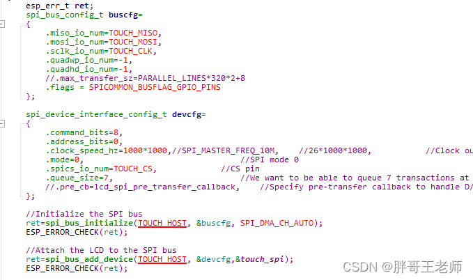
这里的配置要重点看一下,尤其是devcfg中,关于命令和地址长度的配置,否则无法正常驱动触摸屏。
还有速率,不适合太高,否则读取数据太快,反而读不到。

XPT2046的使用
简单来说,就是当IRQ引脚电压为高的时候,就表示有触摸操作,随后读取xy模拟坐标,最后通过边界值,计算出物理坐标。
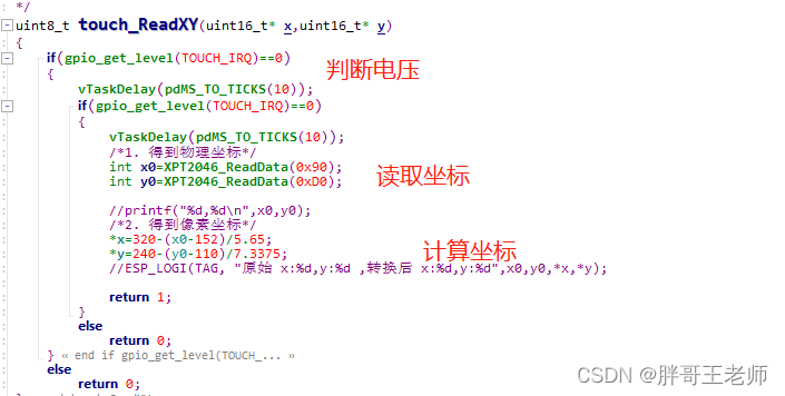
根据不同的屏幕大小,模拟坐标变化范围不一样,所以计算坐标时候的数值也不一样。举个例子
我用的屏幕
-
得到左上角和右下角的模拟量坐标XY极限值
x=1960,y=1871
x=152,y=110 -
转换模拟坐标值范围
x坐标:1960~152 -->1808~0
y坐标:1871~110 --> 1761~0 -
计算斜率,即计算出每个像素对应多少单位模拟量
x坐标的斜率: 1808/320=5.65
y坐标的斜率: 1761/240=7.3375 -
得到实际的像素坐标
x坐标: 320-(模拟量-152)/5.65
y坐标: 240-(模拟量-110)/7.3375
后续可能需要增加一些去抖动。
触摸屏完整驱动
/*
 touch.c
 */

#include <stdio.h>
#include <stdlib.h>
#include <string.h>

#include "freertos/FreeRTOS.h"
#include "freertos/task.h"
#include "driver/gpio.h"
#include "driver/spi_master.h"
#include "esp_timer.h"
#include "esp_err.h"
#include "esp_log.h"
#include "esp_system.h"

static const char *TAG = "touch";


#define TOUCH_HOST    SPI3_HOST

#define TOUCH_MISO 15
#define TOUCH_MOSI 16
#define TOUCH_CLK  17
#define TOUCH_CS   18
#define TOUCH_IRQ  37

static spi_device_handle_t touch_spi;


void touch_spi_init(void)
{
	esp_err_t ret;
	spi_bus_config_t buscfg=
	{
		.miso_io_num=TOUCH_MISO,
		.mosi_io_num=TOUCH_MOSI,
		.sclk_io_num=TOUCH_CLK,
		.quadwp_io_num=-1,
		.quadhd_io_num=-1,
		//.max_transfer_sz=PARALLEL_LINES*320*2+8
		.flags = SPICOMMON_BUSFLAG_GPIO_PINS
	};

	spi_device_interface_config_t devcfg=
	{
		.command_bits=8,
		.address_bits=0,
		.clock_speed_hz=1000*1000,//SPI_MASTER_FREQ_10M,	//26*1000*1000, 		  //Clock out at 26 MHz
		.mode=0,								//SPI mode 0
		.spics_io_num=TOUCH_CS,				//CS pin
		.queue_size=7,							//We want to be able to queue 7 transactions at a time
		//.pre_cb=lcd_spi_pre_transfer_callback,	//Specify pre-transfer callback to handle D/C line
	};

	//Initialize the SPI bus
	ret=spi_bus_initialize(TOUCH_HOST, &buscfg, SPI_DMA_CH_AUTO);
	ESP_ERROR_CHECK(ret);

	//Attach the LCD to the SPI bus
	ret=spi_bus_add_device(TOUCH_HOST, &devcfg,&touch_spi);
	ESP_ERROR_CHECK(ret);

    gpio_set_direction(TOUCH_IRQ, GPIO_MODE_INPUT);
}


/*
函数功能:  读2个字节
说明: 读取16位数据,最低4位数据无效,有效数据是高12位

*/
static uint16_t XPT2046_ReadData(uint8_t cmd)
{

	uint16_t data=0;

	spi_transaction_t t =
	{
	.cmd = cmd,
	.length=16,
	.rxlength = 16,
	.flags = SPI_TRANS_USE_RXDATA,
	};
    esp_err_t ret = spi_device_polling_transmit(touch_spi, &t);
    assert( ret == ESP_OK );

	data=(t.rx_data[0]<<4)+(t.rx_data[1]>>4);
    return data;


}


/*
XPT2046的命令:

10010000  :测试Y的坐标 0x90
11010000  :测试X的坐标 0xD0

返回值:  0表示没有读取到坐标,1表示读取到当前坐标

//1. 得到左上角和右下角的坐标XY极限值
  x=1960,y=1871
  x=152,y=110

//2. 转换坐标值
  x坐标:1960~152 -->1808~0
  y坐标:1871~110 -->  1761~0

//3. 计算斜率
  x坐标的斜率: 1808/320=5.65
  y坐标的斜率: 1761/240=7.3375

//4. 得到实际的像素坐标
  x坐标:  320-(模拟量-152)/5.5
  y坐标:  240-(模拟量-110)/7.3375
*/
uint8_t touch_ReadXY(uint16_t* x,uint16_t* y)
{
	if(gpio_get_level(TOUCH_IRQ)==0)
	{
        vTaskDelay(pdMS_TO_TICKS(10));
		if(gpio_get_level(TOUCH_IRQ)==0)
		{
			vTaskDelay(pdMS_TO_TICKS(10));
			/*1. 得到物理坐标*/
			int x0=XPT2046_ReadData(0x90);
			int y0=XPT2046_ReadData(0xD0);

			//printf("%d,%d\n",x0,y0);
			/*2. 得到像素坐标*/
			*x=320-(x0-152)/5.65;
			*y=240-(y0-110)/7.3375;
			//ESP_LOGI(TAG, "原始 x:%d,y:%d ,转换后 x:%d,y:%d",x0,y0,*x,*y);

			return 1;
		}
		else
			return 0;
	}
	else
		return 0;
}
LVGL修改
demo中默认支持的是 并口,所以要修改为通过SPI方式显示
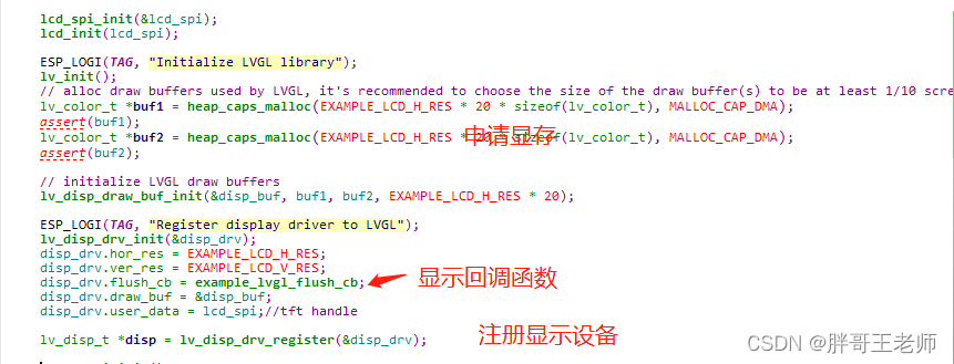
在显示回调 ,调用见面封装的ili9341显示接口。
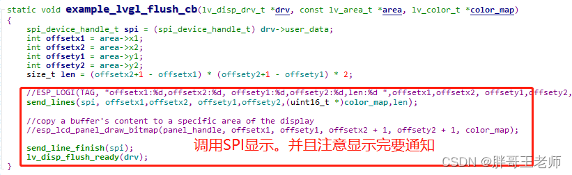
触摸设备同样需要注册
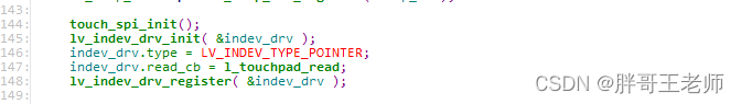
回调函数中,进行坐标读取。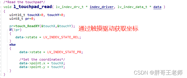
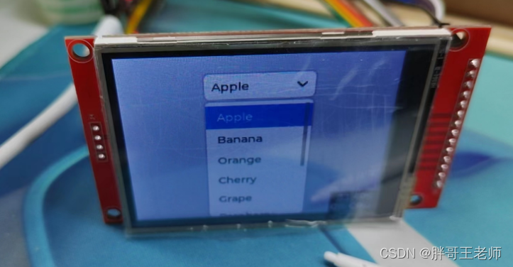
这里调动额select模块测试了一下,触摸还算可以
过程问题
随后在性能提升的时候,配置SPI PSRAM的时候,一旦开启PSRAM,就 出现启动卡主的问题,因为之前一直这样开启,也没问题,一度以为自己的模块坏了。

后来想起来这个关键信息
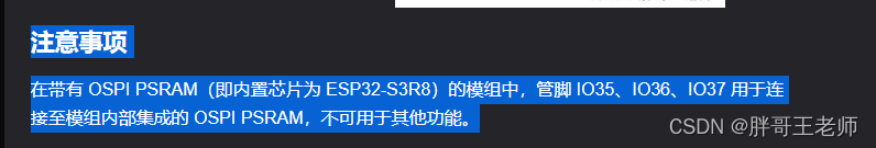
原来是37引脚的问题,所以修改了一下触摸引脚IRQ,问题得到了解决。
再次记录一下完整启动打印
ESP-ROM:esp32s3-20210327
Build:Mar 27 2021
rst:0x1 (POWERON),boot:0x8 (SPI_FAST_FLASH_BOOT)
SPIWP:0xee
mode:DIO, clock div:1
load:0x3fce3808,len:0x1664
load:0x403c9700,len:0xbb8
load:0x403cc700,len:0x2e8c
entry 0x403c9954
I (24) boot: ESP-IDF v4.4.3-dirty 2nd stage bootloader
I (25) boot: compile time 11:10:38
I (25) boot: chip revision: 0
I (27) boot.esp32s3: Boot SPI Speed : 80MHz
I (32) boot.esp32s3: SPI Mode       : DIO
I (36) boot.esp32s3: SPI Flash Size : 16MB
I (41) boot: Enabling RNG early entropy source...
I (47) boot: Partition Table:
I (50) boot: ## Label            Usage          Type ST Offset   Length
I (57) boot:  0 nvs              WiFi data        01 02 00009000 00006000
I (65) boot:  1 phy_init         RF data          01 01 0000f000 00001000
I (72) boot:  2 factory          factory app      00 00 00010000 00100000
I (80) boot: End of partition table
I (84) esp_image: segment 0: paddr=00010020 vaddr=3c050020 size=0df08h ( 57096) map
I (103) esp_image: segment 1: paddr=0001df30 vaddr=3fc93730 size=020e8h (  8424) load
I (105) esp_image: segment 2: paddr=00020020 vaddr=42000020 size=435e0h (275936) map
I (159) esp_image: segment 3: paddr=00063608 vaddr=3fc95818 size=00ce0h (  3296) load
I (160) esp_image: segment 4: paddr=000642f0 vaddr=40374000 size=0f730h ( 63280) load
I (178) esp_image: segment 5: paddr=00073a28 vaddr=50000000 size=00010h (    16) load
I (185) boot: Loaded app from partition at offset 0x10000
I (185) boot: Disabling RNG early entropy source...
I (199) opi psram: vendor id : 0x0d (AP)
I (199) opi psram: dev id    : 0x02 (generation 3)
I (199) opi psram: density   : 0x03 (64 Mbit)
I (203) opi psram: good-die  : 0x01 (Pass)
I (207) opi psram: Latency   : 0x01 (Fixed)
I (212) opi psram: VCC       : 0x01 (3V)
I (217) opi psram: SRF       : 0x01 (Fast Refresh)
I (222) opi psram: BurstType : 0x01 (Hybrid Wrap)
I (228) opi psram: BurstLen  : 0x01 (32 Byte)
I (233) opi psram: Readlatency  : 0x02 (10 cycles@Fixed)
I (239) opi psram: DriveStrength: 0x00 (1/1)
W (244) PSRAM: DO NOT USE FOR MASS PRODUCTION! Timing parameters will be updated in future IDF version.
I (254) spiram: Found 64MBit SPI RAM device
I (259) spiram: SPI RAM mode: sram 80m
I (263) spiram: PSRAM initialized, cache is in normal (1-core) mode.
I (270) cpu_start: Pro cpu up.
I (274) cpu_start: Starting app cpu, entry point is 0x40375328
0x40375328: call_start_cpu1 at E:/esp32_new_tools/Espressif/frameworks/esp-idf-v4.4.3/components/esp_system/port/cpu_start.c:148

I (0) cpu_start: App cpu up.
I (700) spiram: SPI SRAM memory test OK
I (709) cpu_start: Pro cpu start user code
I (709) cpu_start: cpu freq: 240000000
I (709) cpu_start: Application information:
I (712) cpu_start: Project name:     lcd_lvgl
I (717) cpu_start: App version:      1
I (721) cpu_start: Compile time:     Jan 30 2023 11:09:49
I (727) cpu_start: ELF file SHA256:  07e942fc9d6734b0...
I (733) cpu_start: ESP-IDF:          v4.4.3-dirty
I (739) heap_init: Initializing. RAM available for dynamic allocation:
I (746) heap_init: At 3FC9F478 len 0004A298 (296 KiB): D/IRAM
I (752) heap_init: At 3FCE9710 len 00005724 (21 KiB): STACK/DRAM
I (759) heap_init: At 3FCF0000 len 00008000 (32 KiB): DRAM
I (765) heap_init: At 600FE000 len 00002000 (8 KiB): RTCRAM
I (772) spiram: Adding pool of 8192K of external SPI memory to heap allocator
I (780) spi_flash: detected chip: gd
I (784) spi_flash: flash io: dio
I (788) sleep: Configure to isolate all GPIO pins in sleep state
I (794) sleep: Enable automatic switching of GPIO sleep configuration
I (802) cpu_start: Starting scheduler on PRO CPU.
I (0) cpu_start: Starting scheduler on APP CPU.
I (822) spiram: Reserving pool of 32K of internal memory for DMA/internal allocations
LCD ID: 00000000
ILI9341 detected.
LCD ILI9341 initialization.
I (1222) s3_lvgl: Initialize LVGL library
I (1222) s3_lvgl: Register display driver to LVGL
I (1222) s3_lvgl: Install LVGL tick timer
I (1222) s3_lvgl: Display LVGL animation
只想说一句。如果不能用,你引出来干嘛?让人看着着急吗?

代码下载及参考
完整代码下载
使用方法:
首先拷贝Espressif\frameworks\esp-idf-v4.4.3\examples\peripherals\lcd\lvgl作为工程,
然后将下载内容复制进去,即可完成编译,
其实不太推荐,还是需要自己学习一遍。然后参考前面的问题,进行自己实践更明白。
参考资料
《STM32 入门开发:编写 XPT2046 电阻触摸屏驱动 (模拟 SPI)》

结束语
昨天最大的news大概就是某失踪很久的同学,被发现在校外不远 树林中,一个拉网搜索过的地方,其实感觉最大的可能,就是不是第一现场,100多天,不可能没人看到。所以,真相还没有浮出水面。而且感觉看到的,不一定就是真相,毕竟这么久都没有出来结果。

就像现在的推送机制的存在,你爱看的内容,认同的内容,就会越来越多出现在你的视野里,久而久之,你认为世界就应该是这样,一旦出现了一些不同的声音,你就会认为是少数,是另类,甚至是极端。这就是信息茧房。我们学校的教育也是一样,教育仅仅是一种福利,因为目前的教育带有浓重的儒家思想,偏向于使人遵守规矩,服从管理……
所以为了保持清醒,要多想多思考,并且要保持理性。


 1万+
1万+

 被折叠的 条评论
为什么被折叠?
被折叠的 条评论
为什么被折叠?
 到【灌水乐园】发言


