


准备制作一个接入Chat GPT的智能语音助手,使用ESP32-S3作为主控。配个触摸屏后续可以创造无限可能,不过网上暂时没有Arduino框架下ESP32-S3移植LVGL的详细教程,这里我就简单做个示例,就当巩固一下基础吧。
本移植教程同样适用于ESP32,ESP8266,BL616等,无非就是将屏幕显示接口与触摸设备接口接入LVGL,读完本教程希望读者能掌握其本质,举一反三。
一、创建工程
首先在platform io创建一个基于arduino框架的ESP32-S3工程

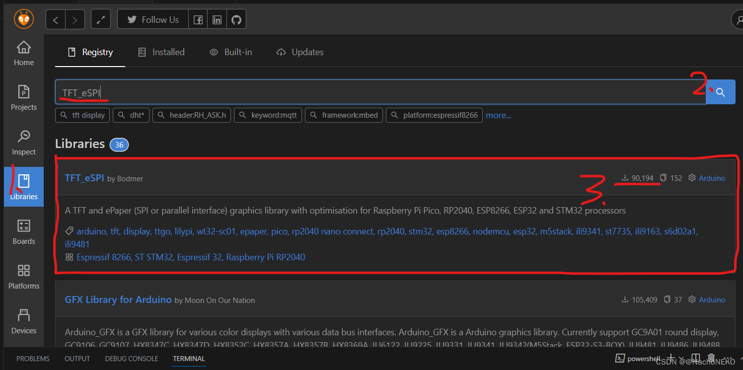
二、下载LVGL依赖库TFT_eSPI
TFT_eSPI库是通过SPI方式驱动LCD屏幕的一个Arduino库,并且支持Platform IO IDE一键下载使用。对于Arduino模式开发的屏幕开发既便捷又稳定。
LVGL GUI开发的底层驱动接口也是使用TFT_eSPI库的API。
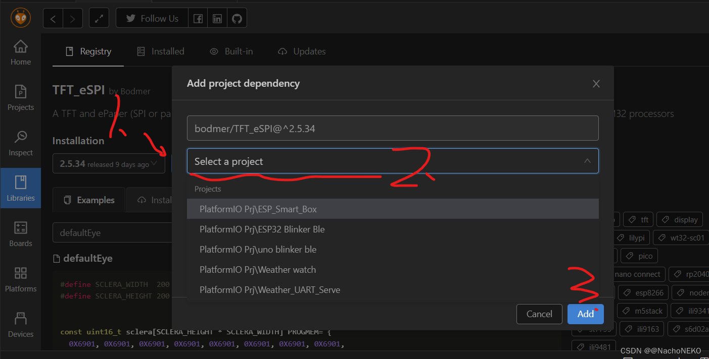
选择添加到当前工程
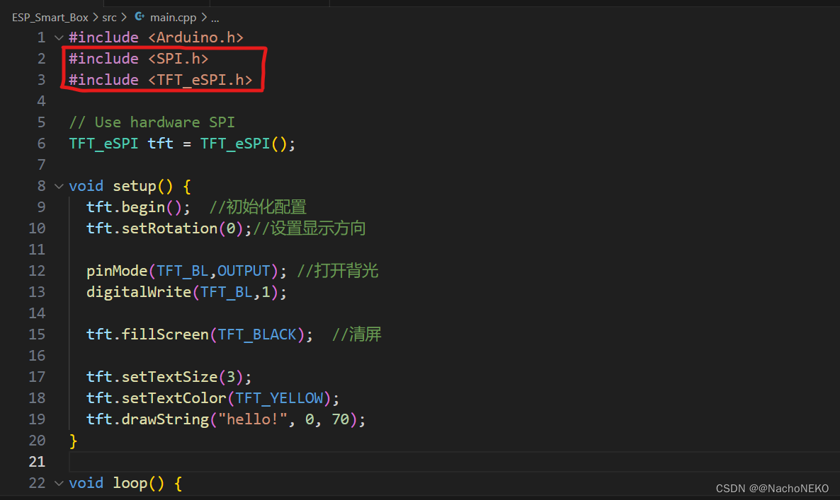
将头文件引入工程,并进行一些初始化配置
最重要的是根据屏幕型号配置驱动文件User_Setup.h文件,在这里
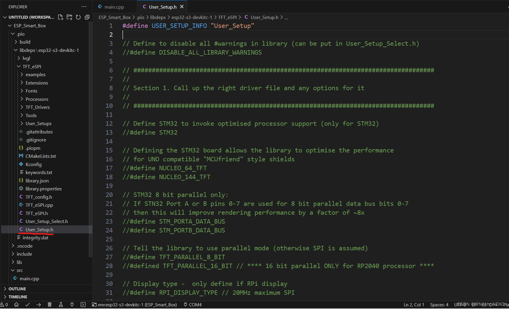
User_Setup.h文件具体有用的配置我留下来了,前面的注释已经说明功能了。我使用的屏幕驱动芯片型号为ST7789V,所以取消对应注释。
#define USER_SETUP_INFO "User_Setup"

// Define to disable all #warnings in library (can be put in User_Setup_Select.h)
//#define DISABLE_ALL_LIBRARY_WARNINGS

// Tell the library to use parallel mode (otherwise SPI is assumed)
//#define TFT_PARALLEL_8_BIT
//#defined TFT_PARALLEL_16_BIT // **** 16 bit parallel ONLY for RP2040 processor ****

// Display type -  only define if RPi display
//#define RPI_DISPLAY_TYPE // 20MHz maximum SPI

// Only define one driver, the other ones must be commented out
//#define ILI9341_DRIVER       // Generic driver for common displays
//#define ILI9341_2_DRIVER     // Alternative ILI9341 driver, see https://github.com/Bodmer/TFT_eSPI/issues/1172
//#define ST7735_DRIVER      // Define additional parameters below for this display
//#define ILI9163_DRIVER     // Define additional parameters below for this display
//#define S6D02A1_DRIVER
//#define RPI_ILI9486_DRIVER // 20MHz maximum SPI
//#define HX8357D_DRIVER
//#define ILI9481_DRIVER
//#define ILI9486_DRIVER
//#define ILI9488_DRIVER     // WARNING: Do not connect ILI9488 display SDO to MISO if other devices share the SPI bus (TFT SDO does NOT tristate when CS is high)
#define ST7789_DRIVER      // Full configuration option, define additional parameters below for this display
//#define ST7789_2_DRIVER    // Minimal configuration option, define additional parameters below for this display
//#define R61581_DRIVER
//#define RM68140_DRIVER
//#define ST7796_DRIVER
//#define SSD1351_DRIVER
//#define SSD1963_480_DRIVER
//#define SSD1963_800_DRIVER
//#define SSD1963_800ALT_DRIVER
//#define ILI9225_DRIVER
//#define GC9A01_DRIVER


// To use the SDA line for reading data from the TFT uncomment the following line:
// #define TFT_SDA_READ      // This option is for ESP32 ONLY, tested with ST7789 and GC9A01 display only

// For ST7735, ST7789 and ILI9341 ONLY, define the colour order IF the blue and red are swapped on your display
// Try ONE option at a time to find the correct colour order for your display
#define TFT_RGB_ORDER TFT_RGB  // Colour order Red-Green-Blue
//#define TFT_RGB_ORDER TFT_BGR  // Colour order Blue-Green-Red

 #define TFT_WIDTH  240
 #define TFT_HEIGHT 320

// If colours are inverted (white shows as black) then uncomment one of the next
// 2 lines try both options, one of the options should correct the inversion.

//#define TFT_INVERSION_ON
#define TFT_INVERSION_OFF

//Define the pins that are used to interface with the display here

#define TFT_MOSI 17
#define TFT_SCLK 18
#define TFT_CS   14
#define TFT_DC   13
#define TFT_RST  16
#define TFT_BL   15
#define TFT_BACKLIGHT_ON HIGH  // Level to turn ON back-light (HIGH or LOW)

//#define TOUCH_CS 21  // Chip select pin (T_CS) of touch screen


// ##################################################################################
//
// Section 3. Define the fonts that are to be used here
//
// ##################################################################################

// Comment out the #defines below with // to stop that font being loaded
// The ESP8366 and ESP32 have plenty of memory so commenting out fonts is not
// normally necessary. If all fonts are loaded the extra FLASH space required is
// about 17Kbytes. To save FLASH space only enable the fonts you need!

#define LOAD_GLCD   // Font 1. Original Adafruit 8 pixel font needs ~1820 bytes in FLASH
#define LOAD_FONT2  // Font 2. Small 16 pixel high font, needs ~3534 bytes in FLASH, 96 characters
#define LOAD_FONT4  // Font 4. Medium 26 pixel high font, needs ~5848 bytes in FLASH, 96 characters
#define LOAD_FONT6  // Font 6. Large 48 pixel font, needs ~2666 bytes in FLASH, only characters 1234567890:-.apm
#define LOAD_FONT7  // Font 7. 7 segment 48 pixel font, needs ~2438 bytes in FLASH, only characters 1234567890:-.
#define LOAD_FONT8  // Font 8. Large 75 pixel font needs ~3256 bytes in FLASH, only characters 1234567890:-.
//#define LOAD_FONT8N // Font 8. Alternative to Font 8 above, slightly narrower, so 3 digits fit a 160 pixel TFT
#define LOAD_GFXFF  // FreeFonts. Include access to the 48 Adafruit_GFX free fonts FF1 to FF48 and custom fonts

// Comment out the #define below to stop the SPIFFS filing system and smooth font code being loaded
// this will save ~20kbytes of FLASH
#define SMOOTH_FONT


// Define the SPI clock frequency, this affects the graphics rendering speed. Too
// fast and the TFT driver will not keep up and display corruption appears.
// With an ILI9341 display 40MHz works OK, 80MHz sometimes fails
// With a ST7735 display more than 27MHz may not work (spurious pixels and lines)
// With an ILI9163 display 27 MHz works OK.

// #define SPI_FREQUENCY   1000000
// #define SPI_FREQUENCY   5000000
// #define SPI_FREQUENCY  10000000
// #define SPI_FREQUENCY  20000000
#define SPI_FREQUENCY  27000000
// #define SPI_FREQUENCY  40000000
// #define SPI_FREQUENCY  55000000 // STM32 SPI1 only (SPI2 maximum is 27MHz)
// #define SPI_FREQUENCY  80000000

// Optional reduced SPI frequency for reading TFT
#define SPI_READ_FREQUENCY  20000000

// The XPT2046 requires a lower SPI clock rate of 2.5MHz so we define that here:
#define SPI_TOUCH_FREQUENCY  2500000

// The ESP32 has 2 free SPI ports i.e. VSPI and HSPI, the VSPI is the default.
// If the VSPI port is in use and pins are not accessible (e.g. TTGO T-Beam)
// then uncomment the following line:
//#define USE_HSPI_PORT

// Comment out the following #define if "SPI Transactions" do not need to be
// supported. When commented out the code size will be smaller and sketches will
// run slightly faster, so leave it commented out unless you need it!

// Transaction support is needed to work with SD library but not needed with TFT_SdFat
// Transaction support is required if other SPI devices are connected.

// Transactions are automatically enabled by the library for an ESP32 (to use HAL mutex)
// so changing it here has no effect

// #define SUPPORT_TRANSACTIONS
配置好了可以接上屏幕烧录代码试试能否正常驱动显示。
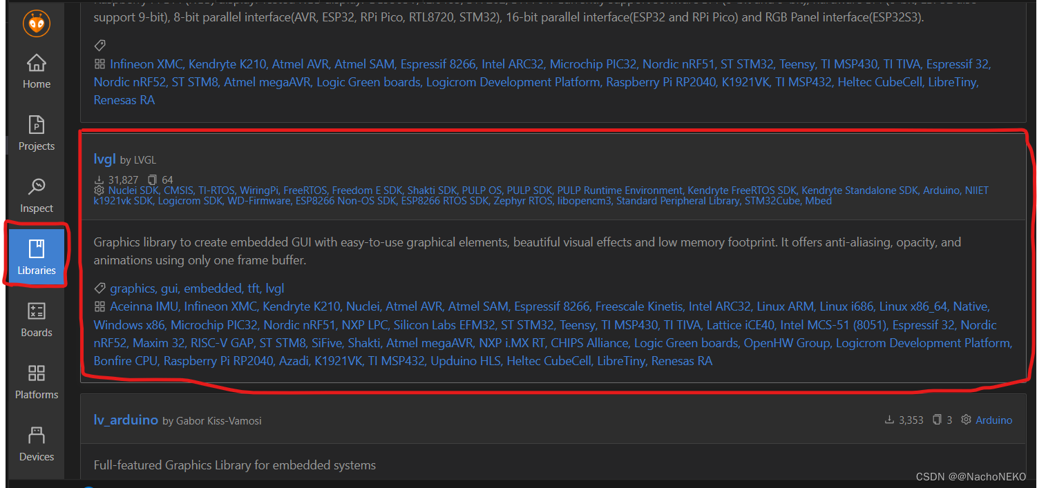
三、下载并配置LVGL库
1.下载LVGL库,在libraries直接搜索lvgl并添加到工程,过程同TFT_eSPI.
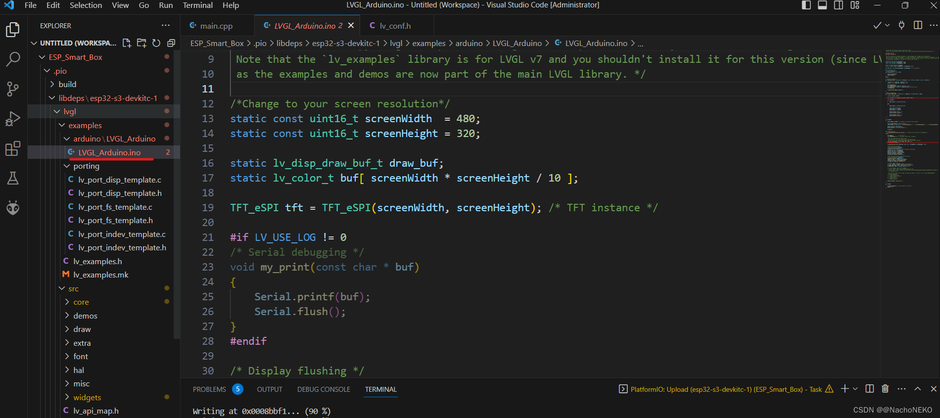
2.由于下载的LVGL包很多东西用不上,我将下载的LVGL库进行了裁剪,最终效果如下,注意不要删错文件了。lv_conf_template.h文件要重命名为lv_conf.h。demos文件夹要移动到src下面,不然运行例程编译时会找不到.c文件。
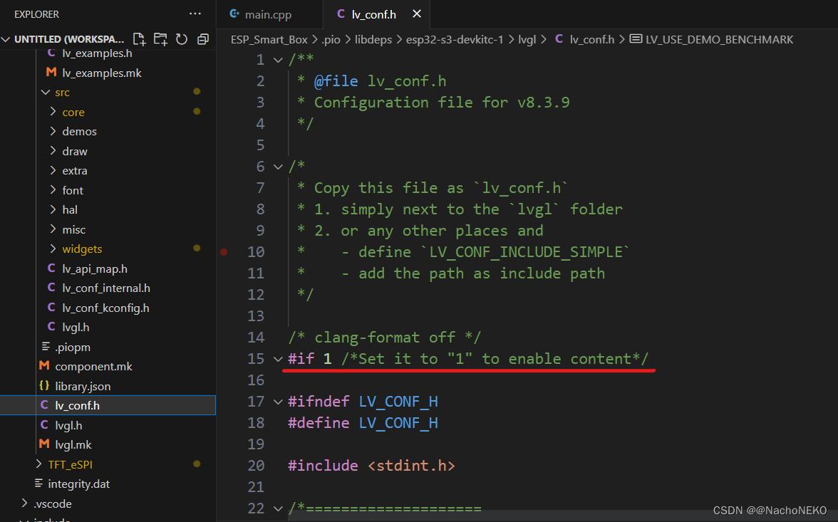
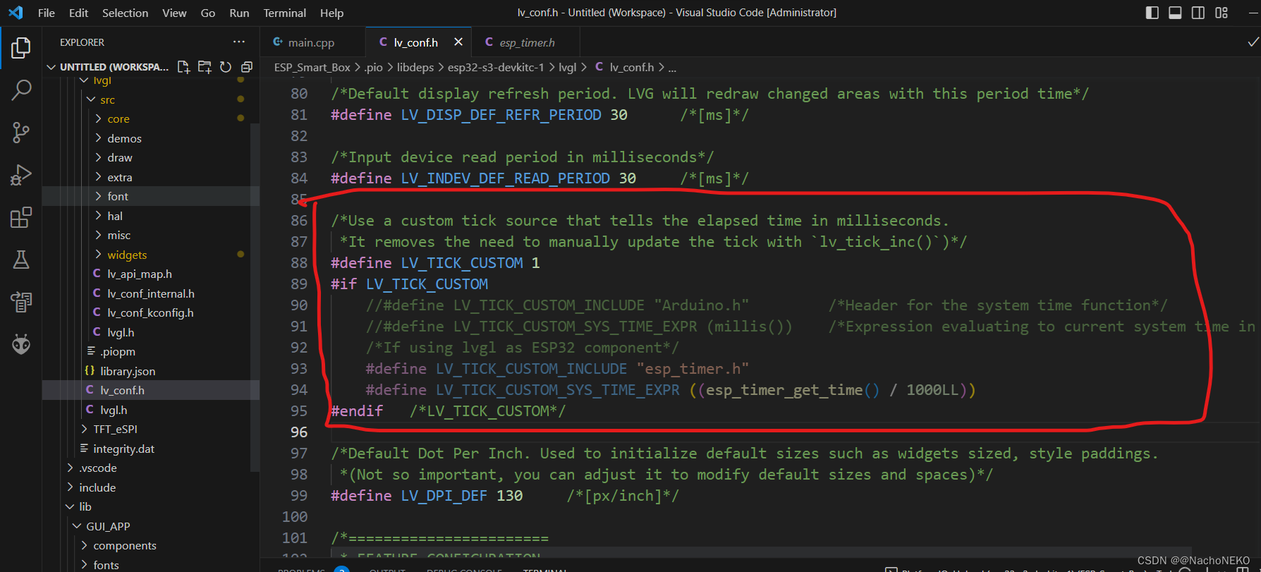
3.配置lv_conf.h文件
先置1使能配置,关于里面的具体每一个宏定义什么功能请耐心阅读英文注释
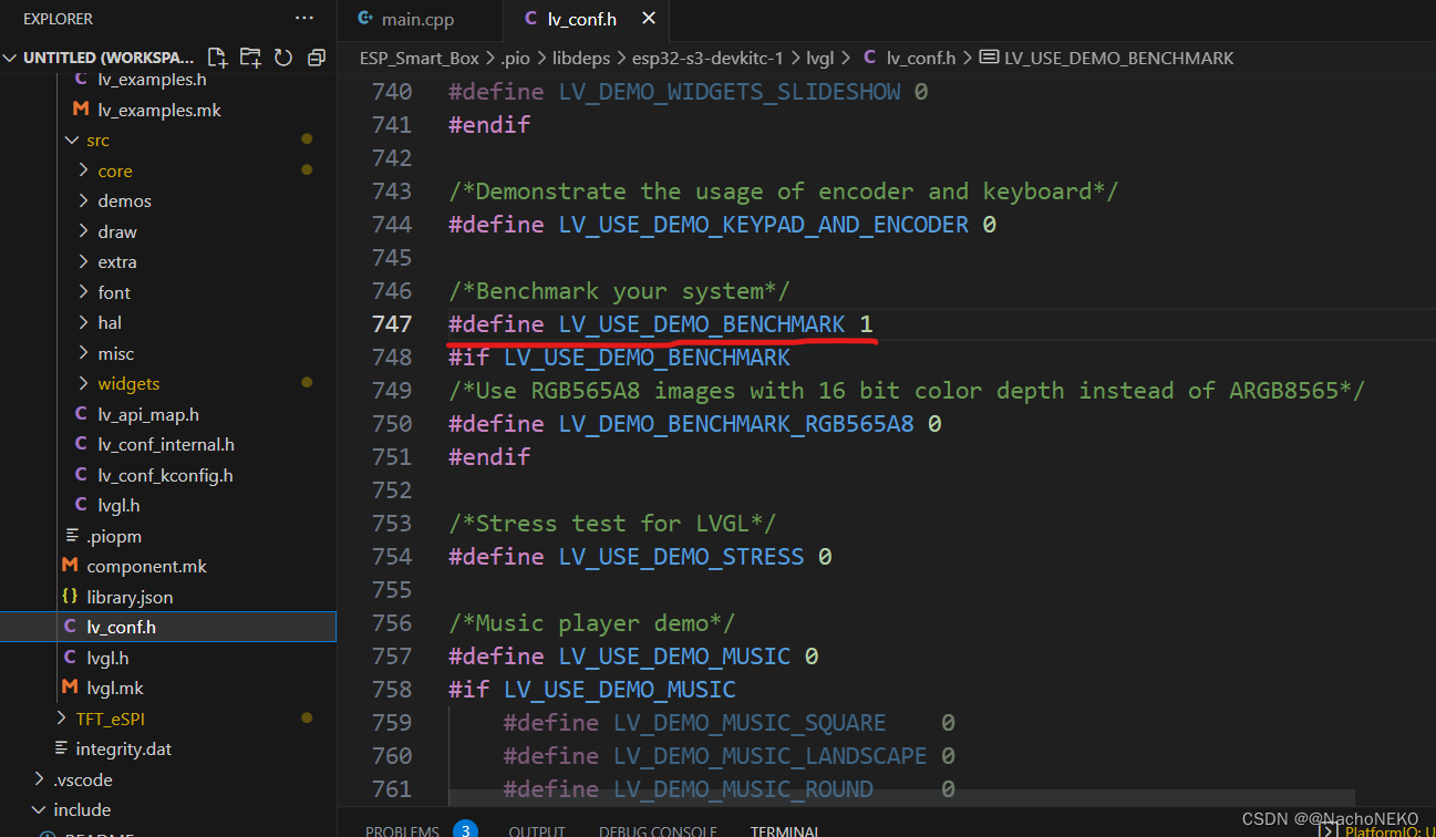
由于我们后面要测试例程,所以需要使能对应例程宏定义
四、配置显示接口并运行例程
将屏幕显示接口接入LVGL有两种方式
1.第一种请参考examples文件夹下的arduino例程
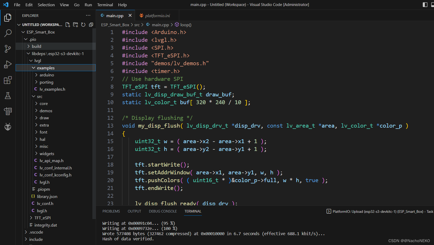
这里直接贴出参考arduino例程后的配置代码,然后你就可以编译烧录到板子上查看运行例程了
main.cpp文件
#include <Arduino.h>
#include <lvgl.h>
#include <SPI.h>
#include <TFT_eSPI.h>
#include "demos/lv_demos.h"
#include <timer.h>
// Use hardware SPI
TFT_eSPI tft = TFT_eSPI();
static lv_disp_draw_buf_t draw_buf;
static lv_color_t buf[ 320 * 240 / 10 ];

/* Display flushing */
void my_disp_flush( lv_disp_drv_t *disp_drv, const lv_area_t *area, lv_color_t *color_p )
{
    uint32_t w = ( area->x2 - area->x1 + 1 );
    uint32_t h = ( area->y2 - area->y1 + 1 );

    tft.startWrite();
    tft.setAddrWindow( area->x1, area->y1, w, h );
    tft.pushColors( ( uint16_t * )&color_p->full, w * h, true );
    tft.endWrite();

    lv_disp_flush_ready( disp_drv );
}

void setup() {

  lv_init();
  tft.begin();  //初始化配置
  tft.setRotation(3);//设置显示方向

  pinMode(TFT_BL,OUTPUT); //打开背光
  digitalWrite(TFT_BL,1);

  lv_disp_draw_buf_init( &draw_buf, buf, NULL, 320 * 240 / 10 );

  /*Initialize the display*/
  static lv_disp_drv_t disp_drv;
  lv_disp_drv_init( &disp_drv );
  /*Change the following line to your display resolution*/
  disp_drv.hor_res = 320;
  disp_drv.ver_res = 240;
  disp_drv.flush_cb = my_disp_flush;
  disp_drv.draw_buf = &draw_buf;
  lv_disp_drv_register( &disp_drv );

  lv_demo_benchmark();
  Timer0_Init();  //provide 1ms heart beating
}

void loop() {
  lv_timer_handler(); /* let the GUI do its work */
  delay( 1 );
}
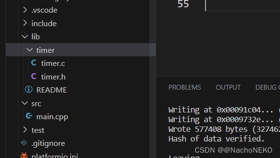
然后就是定时器提供心跳包接口文件,建议放在lib下面,详情请阅读下面的README文件
timer.h文件
#ifndef __TIMER_H__
#define __TIMER_H__

//extern "C"的主要作用就是为了能够正确实现C++代码调用其他C语言代码。
//加上extern "C"后,会指示编译器这部分代码按C语言(而不是C++)的方式进行编译。
#ifdef __cplusplus
extern "C" {
#endif

#include <Arduino.h>

void Timer0_Init(void);

#ifdef __cplusplus
} /*extern "C"*/
#endif

#endif
timer.c文件
#include "timer.h"
#include <lvgl.h>

hw_timer_t * timer = NULL;

void Timer0_IRQ() //1ms中断一次
{
    lv_tick_inc(1); //提供LVGL运行的心跳包
}

void Timer0_Init()
{
  timer = timerBegin(0, 80, true);  //1MHZ,向上计数
  timerAttachInterrupt(timer, &Timer0_IRQ, true);  //开定时器中断
  timerAlarmWrite(timer, 1000, true); //溢出值1000,自动重装载
  timerAlarmEnable(timer);//使能定时器报警功能
}
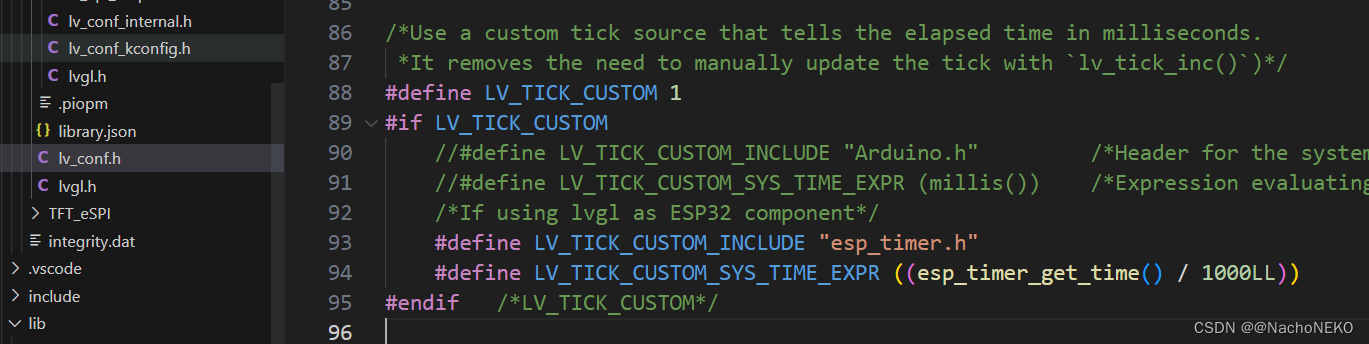
其实也可以直接使用ESP32内部的获取时钟函数,这样就不用单独提供心跳包了。
2.第二种方法则是修改examples文件下面的porting文件,我的建议是使用此方式,一是便于管理,二是官方给预留了其他的设备接口,可以方便调用。可以直接把porting文件夹移动到lib文件夹下。后面触摸功能也是差不多的操作,我就不在示例了。
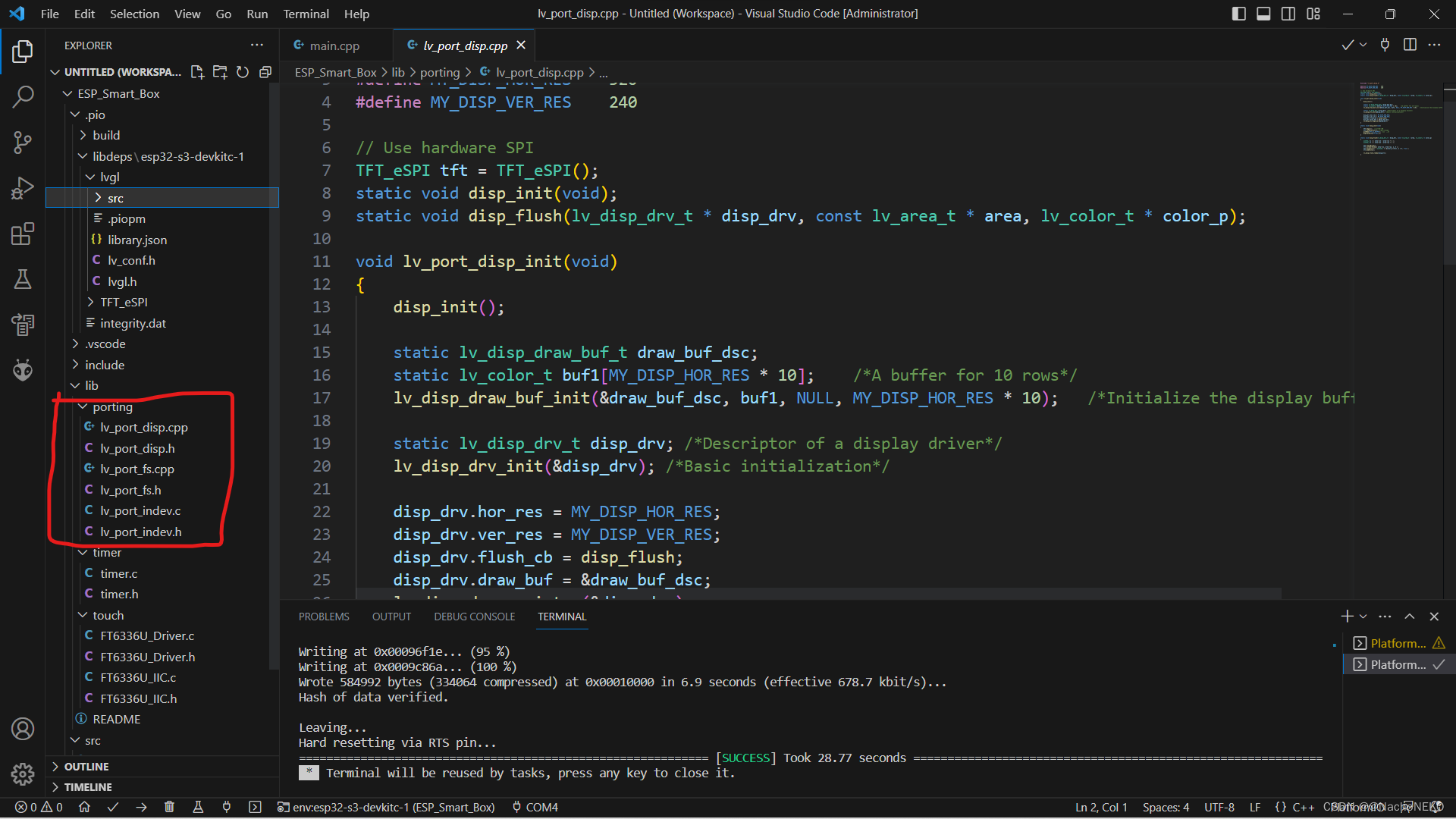
注意.cpp文件与.c文件的区别以及根据引用的其他头文件类型决定是否使用extern C。我把屏幕驱动文件里面没用的东西都删了,留下了最简的形式。
lv_port_disp.cpp文件
#include "lv_port_disp.h"

#define MY_DISP_HOR_RES    320
#define MY_DISP_VER_RES    240

// Use hardware SPI
TFT_eSPI tft = TFT_eSPI();
static void disp_init(void);
static void disp_flush(lv_disp_drv_t * disp_drv, const lv_area_t * area, lv_color_t * color_p);

void lv_port_disp_init(void)
{
    disp_init();

    static lv_disp_draw_buf_t draw_buf_dsc;
    static lv_color_t buf1[MY_DISP_HOR_RES * 10];    /*A buffer for 10 rows*/
    lv_disp_draw_buf_init(&draw_buf_dsc, buf1, NULL, MY_DISP_HOR_RES * 10);   /*Initialize the display buffer*/

    static lv_disp_drv_t disp_drv; /*Descriptor of a display driver*/
    lv_disp_drv_init(&disp_drv); /*Basic initialization*/

    disp_drv.hor_res = MY_DISP_HOR_RES;
    disp_drv.ver_res = MY_DISP_VER_RES;
    disp_drv.flush_cb = disp_flush;
    disp_drv.draw_buf = &draw_buf_dsc;
    lv_disp_drv_register(&disp_drv);
}

static void disp_init(void)
{
    tft.begin();  //初始化配置
    tft.setRotation(3);//设置显示方向
    pinMode(TFT_BL,OUTPUT); //打开背光
    digitalWrite(TFT_BL,1);
}

static void disp_flush(lv_disp_drv_t * disp_drv, const lv_area_t * area, lv_color_t * color_p)
{
    uint32_t w = ( area->x2 - area->x1 + 1 );
    uint32_t h = ( area->y2 - area->y1 + 1 );

    tft.startWrite();
    tft.setAddrWindow( area->x1, area->y1, w, h );
    tft.pushColors( ( uint16_t * )&color_p->full, w * h, true );
    tft.endWrite();

    lv_disp_flush_ready(disp_drv);
}
lv_port_disp.h文件
#ifndef LV_PORT_DISP_H
#define LV_PORT_DISP_H

#include <Arduino.h>
#include <stdbool.h>
#include <TFT_eSPI.h>
#include "lvgl.h"

void lv_port_disp_init(void);

#endif
五、接入触摸功能
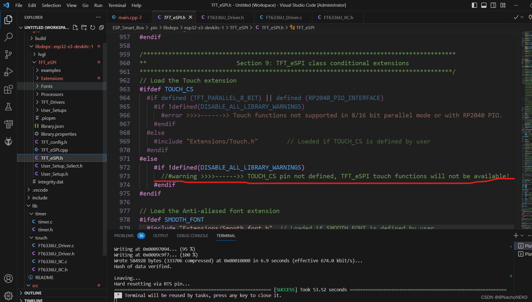
1.虽然TFT_eSPI库提供了触摸屏接口,但是他使用的是XTP2046电阻触摸芯片,SPI驱动。我使用的是电容触摸芯片FT6336U,IIC驱动。所以我们可以把这个警告注释掉,使用自己的驱动程序。
2.触摸芯片驱动程序直接找商家要就行,然后改一下IO口移植过来就行。
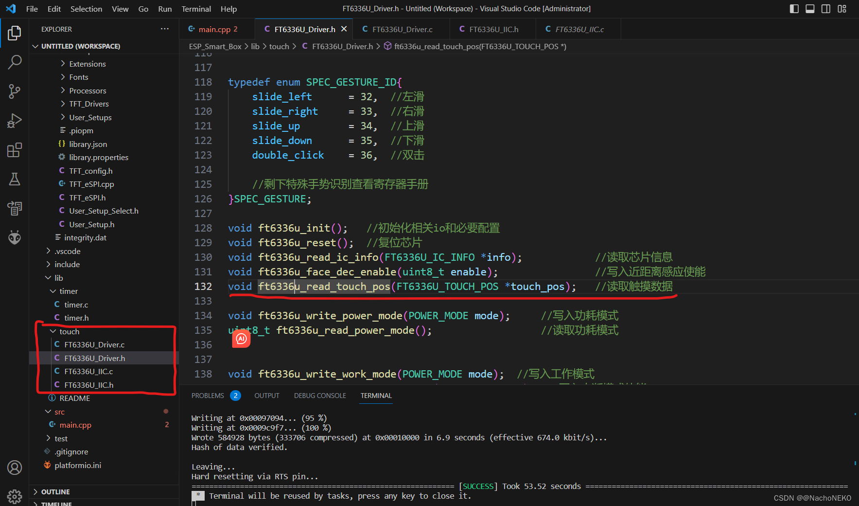
3.然后就是参考两种接入方法,将读取触摸点坐标函数接入LVGL。这里贴出完整示例代码。可以尝试烧录到板子上运行试试,跑完之后可以触摸屏幕查看每个项目的帧率。
第一种方式的完整示例:
#include <Arduino.h>
#include <lvgl.h>
#include <SPI.h>
#include <TFT_eSPI.h>
#include "demos/lv_demos.h"
#include "timer.h"
#include "FT6336U_Driver.h"

// Use hardware SPI
TFT_eSPI tft = TFT_eSPI();
static lv_disp_draw_buf_t draw_buf;
static lv_color_t buf[ 320 * 240 / 10 ];

/* Display flushing */
void my_disp_flush( lv_disp_drv_t *disp_drv, const lv_area_t *area, lv_color_t *color_p )
{
    uint32_t w = ( area->x2 - area->x1 + 1 );
    uint32_t h = ( area->y2 - area->y1 + 1 );

    tft.startWrite();
    tft.setAddrWindow( area->x1, area->y1, w, h );
    tft.pushColors( ( uint16_t * )&color_p->full, w * h, true );
    tft.endWrite();

    lv_disp_flush_ready( disp_drv );
}

/*Read the touchpad*/
void my_touchpad_read( lv_indev_drv_t * indev_drv, lv_indev_data_t * data )
{
    FT6336U_TOUCH_POS touch;//储存触摸信息
    ft6336u_read_touch_pos(&touch); //读取触摸数据

    if( !touch.touch_num )	//识别到有触摸点
    {
        data->state = LV_INDEV_STATE_REL;
    }
    else
    {
        data->state = LV_INDEV_STATE_PR;
        /*Set the coordinates*/
        data->point.x = touch.touch0_y;//如果发现触摸反向,交换一下x,y坐标
        data->point.y = touch.touch0_x;
    }
}

void setup() {

  lv_init();
  tft.begin();  //初始化配置
  tft.setRotation(3);//设置显示方向

  pinMode(TFT_BL,OUTPUT); //打开背光
  digitalWrite(TFT_BL,1);

  lv_disp_draw_buf_init( &draw_buf, buf, NULL, 320 * 240 / 10 );

  /*Initialize the display*/
  static lv_disp_drv_t disp_drv;
  lv_disp_drv_init( &disp_drv );
  /*Change the following line to your display resolution*/
  disp_drv.hor_res = 320;
  disp_drv.ver_res = 240;
  disp_drv.flush_cb = my_disp_flush;
  disp_drv.draw_buf = &draw_buf;
  lv_disp_drv_register( &disp_drv );

  ft6336u_init();
  /*Initialize the (dummy) input device driver*/
  static lv_indev_drv_t indev_drv;
  lv_indev_drv_init( &indev_drv );
  indev_drv.type = LV_INDEV_TYPE_POINTER;
  indev_drv.read_cb = my_touchpad_read;
  lv_indev_drv_register( &indev_drv );

  lv_demo_benchmark();
  Timer0_Init();  //provide 1ms heart breaking
}

void loop() {
  lv_timer_handler(); /* let the GUI do its work */
  delay( 1 );
}
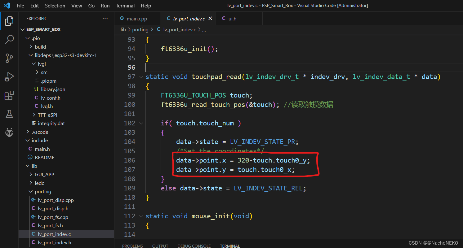
关于触摸这里有个坑提一下,如果发现显示是正常的,也能触摸,但是触摸XY反向了,或者X左右反了,Y左右反了,就需要改一下这里的触摸接口配置。例:先是XY反了,再是X左右反了
第二种方式的完整示例:

很明显,其实这两种方法没区别,哈哈哈。只是封装了一下而已。
这是例程运行演示视频:
ESP32-S3运行LVGL
触摸演示
我使用的屏幕是浦阳的2.8寸电容触摸屏,某宝有卖。使用感觉不错,很丝滑。驱动板我自己画的,商家有卖。
六、运行自己的GUI APP
1.关于如何快速入门LVGL
我的建议是先看视频教程,了解LVGL基本控件的创建以及如何修改样式属性后直接学习如何使用SquareLine,这个也有对应视频教程,然后再学会如何移植就🆗。这里我简单演示一下如何移植。
2.移植SquareLine生成的GUI_APP包到工程
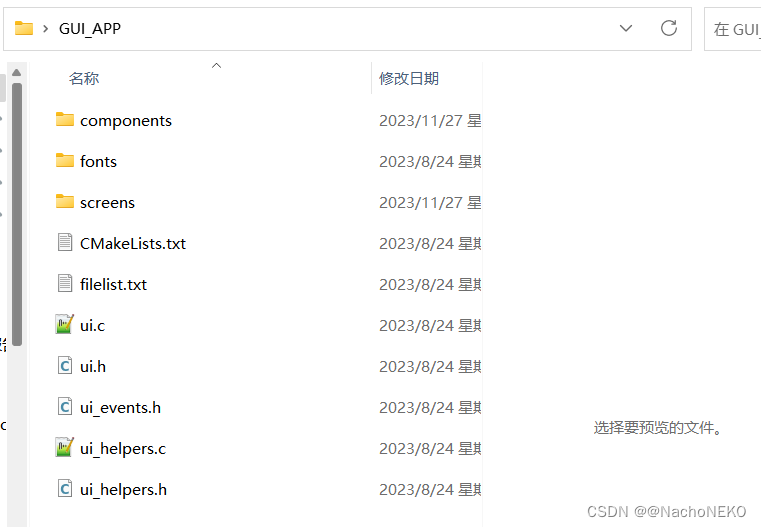
这是我在SquareLine生成的GUI_APP代码,直接整个复制到工程lib文件夹下。
然后在main.c里面引入头文件,初始化控件。
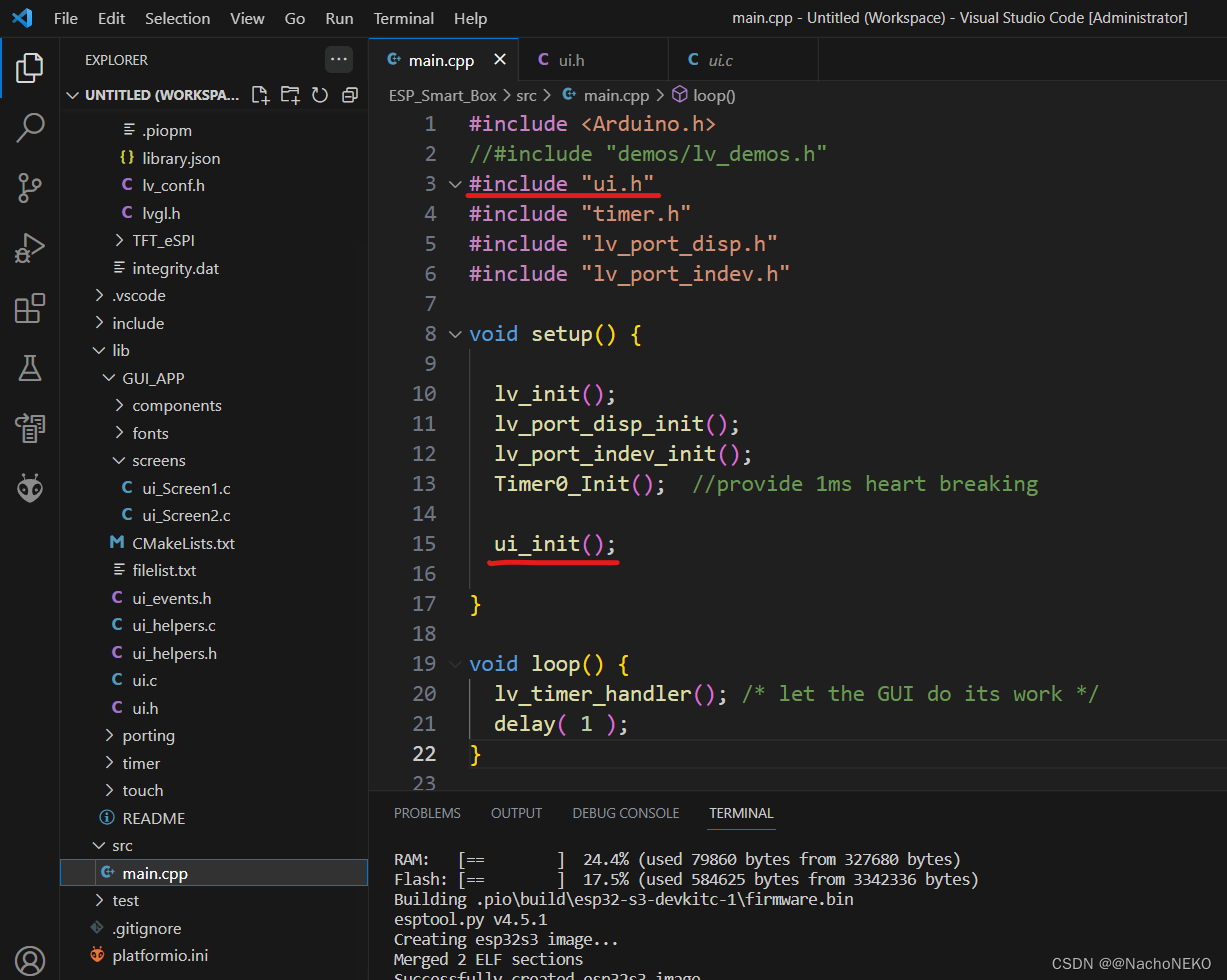
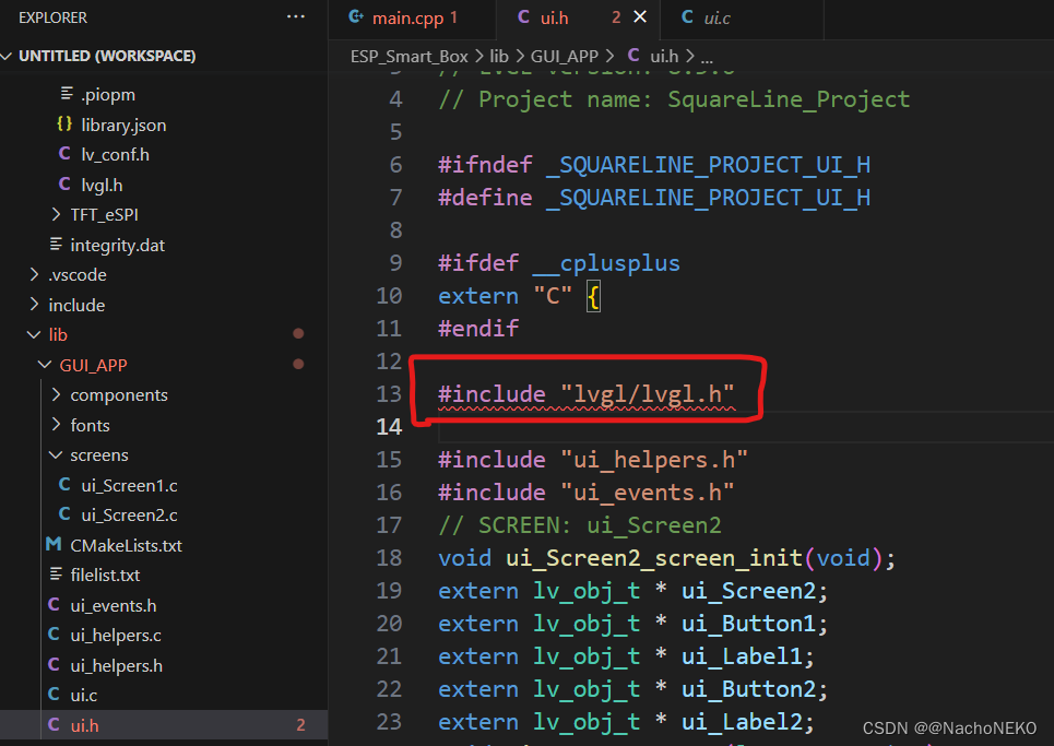
找不到文件就修改一下头文件路径,其他文件同理。
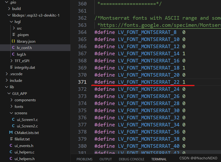
找不到字体是因为在lv_conf.h文件里面没有使能该字体宏定义,把对应字体宏定义置1就行

然后就🆗了,是不是很简单。
七、引入FreeRTOS操作系统
FreeRTOS 内核已移植到 ESP 芯片的所有 CPU 架构(即 Xtensa 和 RISC-V)中。关于ESP32的多核FreeRTOS在官网有详细讲解ESP32 FreeRTOS,此处只做最后的代码示例:
#include <Arduino.h>
#include "demos/lv_demos.h"
//#include "ui.h"
//#include "timer.h"
#include "lv_port_disp.h"
#include "lv_port_indev.h"

void lvgl_task(void *pvParameters)
{
  while(1)
  {
    lv_task_handler();  //开启LVGL任务调度
    vTaskDelay( 20 );
  }
  vTaskDelete(NULL);
}

void setup() {

  lv_init();
  lv_port_disp_init();
  lv_port_indev_init();
  //Timer0_Init();  //provide 1ms heart breaking
  lv_demo_benchmark();
  //ui_init();

  xTaskCreate(  lvgl_task,      //任务函数名
                "Analog Read",  //任务标识
                4096,           //任务堆栈大小
                NULL,
                1,              //任务优先级
                NULL
              );
}

void loop()
{

}
注意上面的心跳包我用这里的配置替代了。
如果读者并不了解FreeRTOS,那我建议可以先阅读正点原子的STM32F1 FreeRTOS应用文档,知道如何移植如何使用之后再去阅读野火的FreeRTOS教程以及core-M3权威指南。前者主讲应用,后者偏向底层原理及应用。


 2724
2724

 被折叠的 条评论
为什么被折叠?
被折叠的 条评论
为什么被折叠?
 到【灌水乐园】发言


