


01_Melexis_Software Development Kit Description.PDF
MLX81330/32 Application Note
Software Development Kit Description
1 Goal
This document is intended to give a brief introduction to the different parts of the MLX81330 and MLX81332 software
development kit. Beside of this document, several other important documentation papers are necessary for a detailed
understanding.
The most important documents related to the software development kit are:
Table 1: Important documentation
Document / Description
-
MLX81330 datasheet
-
MLX81332 datasheet
Description of the MLX81332 with all functions and features
-
Mlx16-fx data book
Description of the included Mlx16-fx microcontroller core and the instruction set
-
GNU C-Compiler GCC
GCC User’s Manual, incl. AS, LD and Getting Started Doc
-
Mlx16 GNU-Debugger
Melexis Debugger Tools, User Manual
-
MUM Manual
Melexis Universal Master Manual
2 Components of the MLX81330/32 Software Development Kit
2.1 Hardware Components
2.1.1 MLX81330
2.1.2 MLX81332
Pinout
Evaluation Board
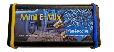
2.1.3 Mini E-MLX Emulator
Figure 1: Mini E-Mlx Emulator
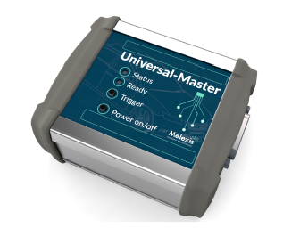
2.1.4 Melexis Universal Master (Optional)
Figure 2: Melexis Universal Master (MUM)
2.2 Software Components
All software components are available for download on the Melexis Softdist server as two installation packages
MLX_Development_Tools_x.y.z.exe and MLX81330_32_Tools_x.y.z.exe.
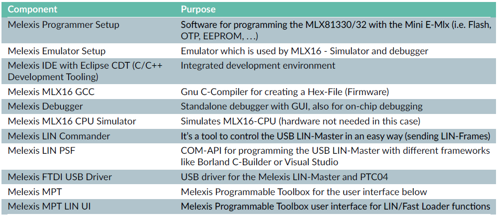
2.2.1 Generic Melexis Development Tools
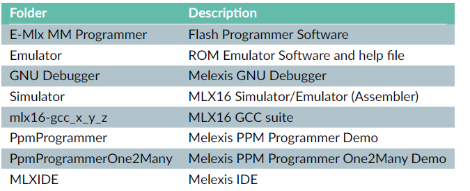
“MLX_Development_Tools_x.y.z.exe” consists of the following components:
Table 4: MLX_Development_Tools_x.y.z.exe package content
2.2.2 Product Specific Development Tools Addon
“MLX81330_32_Tools_x.y.z” consists of the following components:
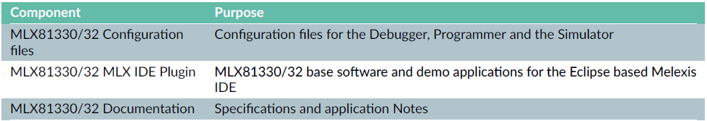
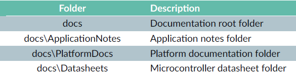
2.2.2.1 MLX81330/32 Documentation
The installation package contains following specifications and application notes:
• Application Notes:
– Software Development Kit Description
– Release Notes
• Platform documentation:
– MLX81330 Programmers Manual
– MLX81332 Programmers Manual
– Mlx16-FX User Reference Manual
– Melexis LIN Firmware API Manual
– LDF Node Generation Utility Manual
• Specification:
– MLX81330 Datasheet
– MLX81332 Datasheet
2.2.3 PPM Programmer Demos
“ppm_programmer_setup_vx_y_z” consists of the following components:
Component / Purpose
PPM Programmer Demo / Demo application for programming a chip using the MUM
“ppm_programmer_one2many_setup_vx_y_z” consists of the following components:
Component / Purpose
PPM Programmer One2Many Demo / Demo application for programming a chip on a bus using the MUM
2.2.4 GNU Debugger Setup
“MlxGnuDebuggerSetup_vx.y.z” consists of the following components:
Component / Purpose
GNU Debugger / Melexis GDB client application
GNU Debugger Server / Melexis GDB server application
GNU Debugger Server Manager / Minimalist UI to manage the Melexis GNU Debugger Server
3 How to use the MLX81330/32 Software Development Kit
The following table introduces the philosophy of the MLX SW Development kit and gives an overview about the
different possibilities of working with the parts that are included in this kit.
Table 9: How to use the SW development kit
| Task | Required Hardware | Required software |
| Software development | PC | MLXIDE, Mlx16 GCC C Compiler |
| Software Simulation | PC | MLXIDE, Mlx16 GNU Debugger |
| In-Circuit Emulation | PC, Mini E-Mlx Emulator, evaluation board | MLXIDE, Mlx16 GNU Debugger |
4 Software Kit
4.1 Software Development in C Language
The necessary documentation for all listed development tools comes along with the respective tool and is therefore not the scope of this document. Software can be written in assembler or in C. The GNU C compiler supports all known features of other common compilers.
• All C language based features can be used
• Assembler parts (previously compiled to object file level) can be included
• In-circuit emulation is possible on C instruction level
NOTE: The object files of GNU and Melexis supplied assembler are not compatible. Therefore the GNU provided
assembler must be used, in case assembler sources should be included in a GNU C source.
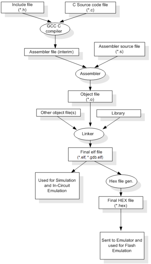
Figure 3: Software development flow using the GNU C tools
4.2 Installation
1. Download the Melexis development tools installation package MLX_Development_Tools_x.y.z.exe from the
Melexis Softdist Server.
2. Start installation by running the setup.
3. Choose the components you need for your development.
4. Choose the installation directory.
5. Wait until the installation process is finished.
6. Download the MLX81330/32 product specific development tools addon installation package
MLX81330_32_Tools_x.y.z.exe from the Melexis Softdist Server.
7. Start installation by running the setup.
8. Choose the components you need for your development.
9. Download the GNU debugger installation package MlxGnuDebuggerSetup_vx.y.z.exe from the Melexis Softdist
Server.
10. Start installation by running the setup.
12. Download the PPM Programmer Demo installation package ppm_programmer_setup_vx_y_z.exe from the Melexis
Softdist Server.
13. Start installation by running the setup.
14. Select Additional tasks options.
15. Wait until the installation process is finished.
4.2.1 Directory Structure of the Software Tools
After installing with this installation option, the following path settings and directory structure appears:
C:\Program Files (x86)\Melexis\
C:\Program Files (x86)\Melexis\MLX81330_32 Tools\
C:\Program Files (x86)\Common Files\Melexis Shared\Config\MLX81330\
C:\Program Files (x86)\Common Files\Melexis Shared\Config\MLX81332\
4.2.2 Directory Structure of the Melexis Base Software
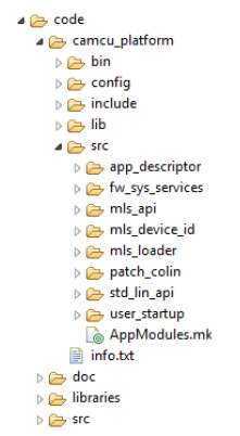
Figure 13: Folder structure
Table 14: Melexis base software folder description
5 Hardware Kit
5.1 General Overview
5.2 MLX81330/32 Evaluation Board (EVB81330/32 QFN24)
Figure 15: MLX81330/32 evaluation board (EVB81330/32 QFN24)
5.3 Mini E-Mlx Supply Interrupter
WARNING: Mini E-Mlx supply interrupter V1.1 (or later) must be used.
Figure 16: Mini E-Mlx supply interrupter
6 Software Development
6.1 Using the C Flow
Editing source code (see chapter 7 and 8 for details):
Start the MLXIDE (‘Start’ -> ‘All Programs’ -> ‘Melexis’ -> ‘MLXIDE’ -> ‘MLXIDE’) and open your source files
Compiling/Linking (see chapter 7 and 8 for details):
Compile the project using the “Build” make target in the MLXIDE -> *.elf, *.gdb.elf and *.hex file will be created in the source code directory
Emulation:
See application note Melexis Debugger Tools, User Manual.
6.2 Application Makefiles
The Makefile functionality was splitted into following three Makefiles:
• Makefile (must not be changed by a customer)
• Makefile.configure.mk (must be modified according to the project requirements)
• Makefile.srcs.mk (must be modified according to the project requirements)
6.2.1 Description - Makefile
The file Makefile located in the application source folder is a fixed general purpose Makefile and must not be changed by a customer.
6.2.2 Description - Makefile.configure.mk
The file Makefile.configure.mk located in the application source folder includes the project specific configurations and must be modified according to the project requirements.
6.2.3 Description - Makefile.srcs.mk
6.3 Programming a HEX file to the Flash
6.3.1 Programming via the Melexis Test-Interface
Since the test mode entry is only allowed during a small timeframe after power on, a Vs power cycling mechanism needs to be added in the setup.
Melexis is providing the Mini E-Mlx Supply Interrupter which can be used for this purpose, make sure to only use the V1.1 or newer.
WARNING: Debugging or programming using the Mini E-Mlx Emulator is not possible at 5V VDDA
6.3.1.1 Procedure
省略。
WARNING: Do not use the ERASE button.
For the Flash memory only “Dump” and “Program using HEX file” operations are allowed. The Flash
programming will automatically include an erase sequence. The “Erase” operation will make the Flash
content to become unknown and on readout it will look like it is being filled with “rubbish”, causing the
Flash protection key also to be unknown, and therefore the chip will no longer be programmable using the
emulator. Recovering the IC can be done via the PPM interface.
6.3.2 Programming via the PPM Interface
6.3.2.1 Hardware Requirements
The Melexis Universal Master (MUM) is used for Flash programming via the LIN-pin for engineering purpose only. For
IC production programming purpose, 3rd party PPM programming tool must be used.
6.3.2.2 PC - Software Requirements
6.3.2.3 Application Software Requirements
In order to be able to use the One2Many demo it is important to enable the mls_device_id module in the makefile.srcs.mk.
6.3.2.3.1 Function bool fw_epm_ApplicationStop(void)
The fw_epm_ApplicationStop() - function is used to switch the application software into a defined state before entering the programming mode. It has to return true to switch into the programming mode. The programming mode is required to upload and verify the Flash memory via the LIN interface. The application must not interrupt these Flash memory operations. In the following is shown an example for the implementation of this function.
fw_lepm_ApplicationStop
6.3.2.4 Flash Upload via LIN pin and Melexis PPM Programmer Demo
• Connect the supply voltage, the Universal-Master, the evaluation board and the Ethernet interface to the PC.
• Start the PPM Programmer (‘Start’ -> ‘All Programs’ -> ‘Melexis PPM Programmer’ -> ‘PPM Programmer’)
• The window “Melexis PPM Programmer Demo” opens.
• To start the upload push the button “Program Flash”
MUM IP/hostname: 192.168.7.2
Figure 21: PPM Programmer Demo GUI
7 First Steps with the Eclipse based Melexis IDE
When starting Eclipse the first time the Eclipse CDT (C/C++ Development Tooling) welcome screen will be shown. This screen can be closed as shown below.
Figure 22: Eclipse CDT welcome screen
In the next step the standard Eclipse CDT perspective has to be changed to the MLXIDE perspective.
Open Perspective -> MlxIDE
The configuration of the Melexis IDE is now finished.
8 First Steps for Building a Software Project
8.1 Create a New Project Using a Provided Project Template
8.2 Select the Melexis MLX16-GCC Compiler Version for the Project
It’s required for each new created project to select the MLX16-GCC version which should be used for the project.
Usually only one MLX16-GCC version is installed but also in this case it’s required to select the version.
8.3 Build the Project
As result the Intel HEX file and the *.gdb.elf file are generated and can now be used with the MLX-IDE or the programmer tools.
8.4 Debugging the Project
Debugging of the target can be done from with the Melexis IDE, the GNU Project Debugger Manual explains how this can be done.
The Melexis MLX81330/32 debugging interface has some limitations which shall be taken into account while debugging:
• During the DUT execution, the debugger cannot show/update memory and/or IO-ports.
• The DUT supports up to max. 4 hardware breakpoints. In case EEPROM patches are loaded, the number of hardware breakpoints will be reduced by the number of patches.
• When DUT enters Sleep-mode, the DUT internal voltage regulators are switched OFF, and therefore the testinterface
can not operate. A reconnection of the debugger shall be required.
• When the application makes a reset (intended or unintended e.g., by Watchdog), the code execution will be halted in the ROM code (MLX81330: 0x37c0-0x37c2; MLX81332: 0x39d8-0x39da), checking for the DUT “in application” bit, only after pausing and continuing the target the CPU will pass this point.
• The IO’s of the test-interface can not be used by the application during debug sessions.
• The test-interface levels are only correct when using the default VDDA voltage level of 3.3V. When switching to 5.0V, the test-interface is no longer functional.
9 Appendix A - Schematics EVB81330/32 QFN24
12 Appendix D - Test-Interface
The Test-Interface uses three pins for the communication between the IC and the Mini E-Mlx.
The test mode entry is only allowed during a small timeframe after power on, therefore it is important to add a method for toggling the VS input of the IC. This can be done via the Melexis Mini E-Mlx Supply Interrupter or by powering the IC’s VS pin from the Mini E-Mlx Vout1 signal.
Table 16: Mini DIN-9 pin-out details
13 Revisions
Table 17: Document history
Revision Description Date
1.0.0 First release 2019-12-19
1.0.1 Correcting test-interface pins 2020-10-09
1.1.0 Do not use the ERASE button 2021-09-07
2.0.0 Upgrades for development tools v2.x 2022-04-13
14 Disclaimer


 被折叠的 条评论
为什么被折叠?
被折叠的 条评论
为什么被折叠?
 到【灌水乐园】发言


