


本系列为作者学习UnityShader入门精要而作的笔记,内容将包括:
- 书本中句子照抄 + 个人批注
- 项目源码
- 一堆新手会犯的错误
- 潜在的太监断更,有始无终
总之适用于同样开始学习Shader的同学们进行有取舍的参考。
获取深度和法线纹理
有的时候我们不仅希望得到当前屏幕的颜色信息,还希望得到深度和法线信息,例如上一章节中用到的边缘检测和运动模糊功能,都可以通过深度和法线纹理来解决。由于深度和法线的图像不受纹理和光照的影响,仅仅保留了渲染物体的模型信息,因此相比于一些图像算法要更加可靠。
复习一下前向渲染和延迟渲染
延迟渲染管线介绍,这篇文章要比我之前写的文章要好。
如何获取深度和法线纹理
深度纹理的深度值范围是[0,1],深度值的获取实际上就是将顶点从模型空间通过MVP变换到NDC之后的z值,不过NDC中的z值范围是[-1,1],因此要应用下式将z值映射为深度值:
d
=
0.5
∗
z
N
D
C
+
0.5
d= 0.5 * z_{NDC} + 0.5
d=0.5∗zNDC+0.5
在前向渲染路径时,由于无法直接获取深度缓存,因此我们只能通过Pass手动计算深度值。同样的也不会保存法线纹理。
而使用延迟渲染路径时,由于渲染管线会将一些信息存储到GBuffer中,例如深度和法线信息。所以是可以直接获取深度缓存和法线缓存的,无法获取时则是通过一个单独的Pass进行计算得到。
Unity会使用着色器替换技术选择RenderType为Opaque类型的物体,判断它们使用的渲染队列是否小于等于2500,如果满足此条件,则把它渲染到深度和法线纹理中去(当且仅当着色器包含ShadowCaster时,才会使用该Pass生成深度纹理)。
在Unity中,我们可以选择让摄像机生成一张深度纹理或者一张深度 + 法线纹理,当选择前者,则只需要一张单独的深度纹理时,Unity会直接获取深度缓存或者按照之前讲到的着色器替换技术,选取需要的不透明物体,并使用它投射阴影时使用的 ShadowCaster Pass来得到深度纹理,此时只使用深度纹理则保存24位或16位精度。
若生成深度 + 法线纹理,则会使用GBuffer的RGBA四通道,每通道8位共计32位精度来保存该纹理,法线信息存储于RG通道,深度信息存储于BA通道。由于延迟渲染会创建深度缓存和法线缓存,因此法线信息和深度信息在延迟渲染中是很容易获得的。而在前向渲染中并不创建法线缓存,因此需要一个单独的Pass再次渲染场景以获取法线信息(在Unity底层内置了一个Pass)
如何在代码中获取
想要获取Unity深度纹理也很简单,只需要一行代码就可以实现:
在C#中:
获取深度纹理camrea.depthTextureMode = DepthTextureMode.Depth;,
获取深度+法线纹理camrea.depthTextureMode = DepthTextureMode.DepthNormals;
通过按位或使得同时生成一张深度纹理和深度 + 法线纹理:
camera.depthTextureMode |= DepthTextureMode.Depth;
camera.depthTextureMode |= DepthTextureMode.DepthNormals;
在Shader中:
我们可以使用名为_CameraDepthTexture的变量来访问深度纹理,若想要对其进行采样,理论上使用tex2D即可,但是为了避免不同平台差异造成的问题,我们需要使用SAMPLE_DEPTH_TEXTURE宏对深度纹理进行采样(该宏采样并直接返回了深度值):
float d = SAMPLE_DEPTH_TEXTURE(_CameraDepthTexture, i.uv);
其中uv坐标是float2类型的变量。若要使用float3类型或float4类型进行投影纹理的采样,则需要使用带有PROJ后缀的宏进行投影纹理采样或变换:
float d = SAMPLE_DEPTH_TEXTURE_PROJ(_CameraDepthTexture, UNITY_PROJ_COORD(i.scrPos));
若采样的是深度 + 法线纹理,则该纹理采样结果需要用float4类型变量来存储,我们可以直接像上面写的代码一样,用一个float4直接进行tex2D的采样然后再分别解码,或者使用ShaderLab中的方法来直接解码出深度和法线纹理信息:
inline void DecodeDepthNormal( float4 enc, out float depth, out float3 normal )
{
	// 通过RG解码深度float
    depth = DecodeFloatRG (enc.zw);
    // 通过BA解码法线方向(两个法线方向就能计算第三个法线方向)
    normal = DecodeViewNormalStereo (enc);
}
当然上面函数中的方法也是可以直接调用的
查看深度和法线纹理
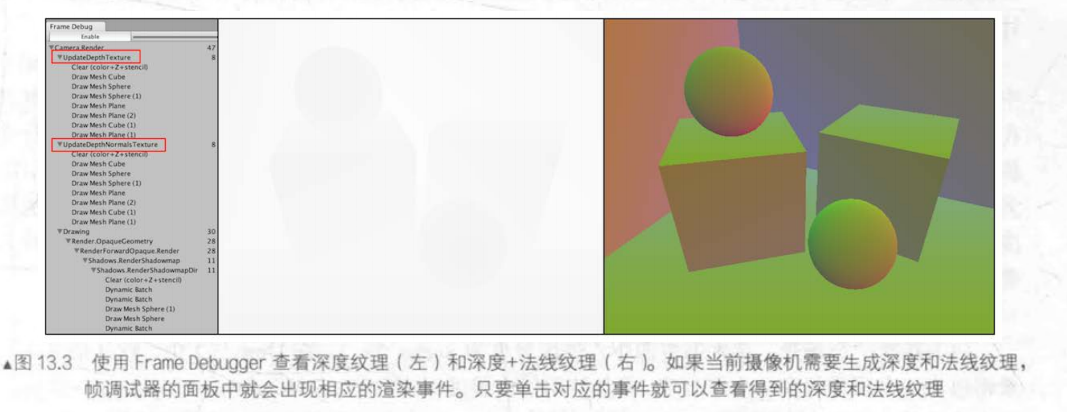
通过FrameDebugger可以查看深度纹理和法线纹理。有时在帧调试器中看到的深度图可能是全黑或者全白的,这是因为远裁剪平面距离近裁剪平面的距离过大导致的,因此若物体距离摄像机太近则NDC会被映射到一个很小的值,看起来就不明显了。

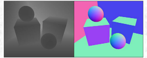
通过在测试时定义片元着色器的输出,可以查看解码后的法线和深度值:
再谈运动模糊
前文中我们学习了如何使用多张屏幕图像混合模拟运动模糊的效果,另一种更加广泛的技术是使用速度映射图,速度映射图存储了每个像素的速度,然后使用这个速度来决定模糊的方向和大小。
速度映射图有几种不同的生成方法,第一种想法是把场景物体的速度都渲染到一张纹理中,但这种方法的缺点在于需要修改场景中所有物体的Shader代码。
第二种方法是通过顶点坐标计算得到的
- 先通过当前帧的VP变换的逆矩阵乘以顶点得到当前世界空间下的顶点坐标
- 再通过对当前帧下世界空间的顶点坐标应用前一帧使用的VP变换得到该顶点在前一帧对应的NDC位置
- 最后再计算前一帧该顶点的NDC坐标和当前帧该顶点对应的刚计算得到的前一帧的NDC坐标之差来得到速度值
这种方法的优点是在一个屏幕后处理中就能完成整个效果的模拟,但缺点是需要在片元着色器中进行两次矩阵乘法的操作,对性能有影响(GPU表示这都不是事)
C#
using System.Collections;
using System.Collections.Generic;
using UnityEngine;

public class CustomMotionBlurWithDepthTexture : CustomPostEffectsBase
{
	public Shader BlurShader;
	private Material m_blurMaterial;
	public Material BaseMaterial
	{
		get
		{
			m_blurMaterial = CheckShaderAndCreateMaterial(BlurShader, m_blurMaterial);
			return m_blurMaterial;
		}
	}
	private Camera myCamera;
	public Camera camera {
		get {
			if (myCamera == null) {
				myCamera = GetComponent<Camera>();
			}
			return myCamera;
		}
	}
	[Range(0.0f, 1.0f)]
	public float blurSize = 0.5f;
	private Matrix4x4 previousViewProjectionMatrix;


	void OnEnable() {
		// 获取深度值
		camera.depthTextureMode |= DepthTextureMode.Depth;

		// 当开启时计算当前帧的vp矩阵
		previousViewProjectionMatrix = camera.projectionMatrix * camera.worldToCameraMatrix;
	}
	override protected void OnRenderImage (RenderTexture source, RenderTexture destination)
	{
		if (BaseMaterial != null) {
			BaseMaterial.SetFloat("_BlurSize", blurSize);

			// 每帧开始渲染时将上一次获取的vp矩阵作为上一帧的vp矩阵传入shader
			BaseMaterial.SetMatrix("_PreviousViewProjectionMatrix", previousViewProjectionMatrix);
			// 当前帧的vp矩阵再计算
			Matrix4x4 currentViewProjectionMatrix = camera.projectionMatrix * camera.worldToCameraMatrix;
			// 获取当前帧的vp矩阵的逆矩阵
			Matrix4x4 currentViewProjectionInverseMatrix = currentViewProjectionMatrix.inverse;
			// 当前帧的vp矩阵的逆矩阵传入shader
			BaseMaterial.SetMatrix("_CurrentViewProjectionInverseMatrix", currentViewProjectionInverseMatrix);
			// 在传入结束后将当前帧获取的vp矩阵作为下次渲染的prevVP矩阵
			previousViewProjectionMatrix = currentViewProjectionMatrix;

			// 我算是知道为什么要在C#里计算矩阵了,比shader中计算方便太多
			Graphics.Blit (source, destination, BaseMaterial);
		} else {
			Graphics.Blit(source, destination);
		}
	}
}
Shader:
Shader "Custom/MotionBlurWithDepthTexture_Copy"
{
    Properties
    {
        _MainTex ("MainTex", 2D) = "white" {}
		_BlurSize ("Blur Size", Float) = 1.0
    }
    SubShader
    {
        CGINCLUDE

		#include "UnityCG.cginc"

		sampler2D _MainTex;
		half4 _MainTex_TexelSize;
		sampler2D _CameraDepthTexture;
		float4x4 _CurrentViewProjectionInverseMatrix;
		float4x4 _PreviousViewProjectionMatrix;
		half _BlurSize;

		struct v2f {
			float4 pos : SV_POSITION;
			half2 uv : TEXCOORD0;
			half2 uv_depth : TEXCOORD1;
		};
		v2f vert(appdata_img v) {
			v2f o;
			o.pos = UnityObjectToClipPos(v.vertex);

			o.uv = v.texcoord;
			o.uv_depth = v.texcoord;

			#if UNITY_UV_STARTS_AT_TOP
			if (_MainTex_TexelSize.y < 0)
				o.uv_depth.y = 1 - o.uv_depth.y;
			#endif

			return o;
		}

		fixed4 frag(v2f i) : SV_Target {
			// 采样深度值
			float depth = SAMPLE_DEPTH_TEXTURE(_CameraDepthTexture, i.uv_depth);

			// 我的一个误区,从NDC空间变换到齐次裁剪空间不需要“齐次乘法”,
			// 因为齐次除法就是除以了VP矩阵的w分量,所以乘以了VP矩阵的逆其实就是应用了所谓齐次乘法

			// 逆运算将深度值以及屏幕采样的像素坐标重新映射回NDC坐标
			float4 H = float4(i.uv.x * 2 - 1, i.uv.y * 2 - 1, depth * 2 - 1, 1);
			// 乘以当前帧vp逆矩阵获得当前帧下像素点对应的世界空间下的四维向量
			float4 D = mul(_CurrentViewProjectionInverseMatrix, H );
			// 再次应用其次除法变换为世界坐标
			float4 worldPos = D / D.w;

			float4 currentPos = H;
			// 用当前世界坐标与前一帧的VP矩阵相乘获得前一帧NDC下的四维向量
			float4 previousPos = mul(_PreviousViewProjectionMatrix, worldPos);
			// 应用其次除法获得NDC坐标
			previousPos /= previousPos.w;

			// 用坐标差的均值计算不同分量上顶点运动的速度
			float2 velocity = (currentPos.xy - previousPos.xy)/2.0f;

			float2 uv = i.uv;
			float4 color = tex2D(_MainTex, uv);
			// 用_BlurSize来控制采样的偏移
			uv += velocity * _BlurSize;

			// 为当前帧根据速度叠加两帧采样偏移的画面,用三帧合并的渲染画面体现运动模糊的效果
			for (int it = 1; it < 3; it++, uv += velocity * _BlurSize) {
				float4 currentColor = tex2D(_MainTex, uv);
				color += currentColor;
			}
			// 对三帧合并的画面计算均值
			color /= 3;

			return fixed4(color.rgb, 1.0);
		}
		ENDCG
		Pass {
			ZTest Always
			Cull Off
			ZWrite Off

			CGPROGRAM

			#pragma vertex vert
			#pragma fragment frag

			ENDCG
		}
    }
}
全局雾效
雾效(Fog)是游戏里常见的一种效果,Unity内置的雾效可以产生基于距离的线性或指数雾效。但是如果想要在Shader中实现雾效,则需要为场景中的所有物体添加相关代码。所以如果添加的是非实体的雾效不建议使用shader实现(体积雾,粒子系统雾效则不同)。
如果只是单纯的视觉效果,可以用屏幕后处理实现全局雾效。这种方法自由性很高,可以模拟各种不同的雾效。
要实现雾效,则需要根据深度纹理来重建每个像素在世界空间下的位置。
重建世界坐标
如何用深度纹理来重建像素在世界空间下的坐标位置,在上一章中,我们是使用VP矩阵的逆乘以当前像素点的NDC坐标。但是使用矩阵运算的计算量还是比较大的,我们可以用线性的方法计算出世界坐标——一个顶点的坐标可以由另一个顶点坐标 + 二者坐标的偏移量来表示,因此我们只需要知道摄像机在世界空间下的位置,以及世界空间下该像素相对于摄像机的偏移量,把它们相加就可以得到像素的世界坐标:
float4 worldPos = _WorldSpaceCameraPos + linearDepth * interpolatedRay;
其中,_WorldSpaceCameraPos 是世界空间下的摄像机位置,可直接通过Unity的内置变量访问。linearDepth * interpolatedRay则是摄像机相对于该像素的偏移量,linearDepth是由深度纹理得到的线性深度值,interpolatedRay是由顶点着色器输出并插值后得到的射线。
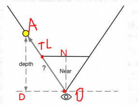
如何根据深度值来计算相对坐标,其实很简单?假设我们要求的是像素点A的世界坐标,而在摄像机下点A在近裁剪平面下的投影位置点是TL。depth是通过深度纹理计算的线性深度值,near是摄像机到近裁剪平面的距离。
观察图像不难发现,三角形ONTL和三角形ADO是相似三角形,因此想要求得OA的模长,则有以下公式:
∣
O
A
∣
D
e
p
t
h
=
∣
T
L
∣
N
e
a
r
\frac{|OA|}{Depth} = \frac{|TL|}{Near}
Depth∣OA∣=Near∣TL∣
所以
∣
O
A
∣
=
∣
T
L
∣
N
e
a
r
∗
D
e
p
t
h
所以|OA| = \frac{|TL|}{Near} * Depth
所以∣OA∣=Near∣TL∣∗Depth
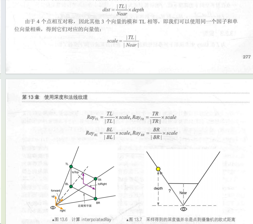
由于近裁剪平面上|TL|,|TR|,|BL|,|BR|的模长相等,因此可以记
s
c
a
l
e
=
∣
T
L
∣
N
e
a
r
scale = \frac{|TL|}{Near}
scale=Near∣TL∣。
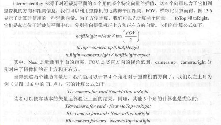
由于传入shader中的RenderTexture只有四个顶点,实际上就是与近裁剪平面相同大小的四边形,因此只需要在片元着色器中对四个顶点进行插值计算即可得到对应像素点相对于摄像机的偏移量,加上摄像机坐标即为在世界空间下的位置。
实现
我们使用lerp函数混合雾效颜色和画面颜色,其中雾效系数f的计算包含了线性,指数和指数的平方三种模式:

C#:
using System.Collections;
using System.Collections.Generic;
using UnityEngine;

public class CustomFogWithDepthTexture : CustomPostEffectsBase
{
	public Shader fogShader;
	private Material fogMaterial = null;

	public Material material {
		get {
			fogMaterial = CheckShaderAndCreateMaterial(fogShader, fogMaterial);
			return fogMaterial;
		}
	}
	private Camera myCamera;
	public Camera camera {
		get {
			if (myCamera == null) {
				myCamera = GetComponent<Camera>();
			}
			return myCamera;
		}
	}
	private Transform myCameraTransform;
	public Transform cameraTransform {
		get {
			if (myCameraTransform == null) {
				myCameraTransform = camera.transform;
			}

			return myCameraTransform;
		}
	}
	[Range(0.0f, 3.0f)]
	public float fogDensity = 1.0f;

	public Color fogColor = Color.white;

	public float fogStart = 0.0f;
	public float fogEnd = 2.0f;
	void OnEnable() {
		camera.depthTextureMode |= DepthTextureMode.Depth;
	}
	override protected void OnRenderImage (RenderTexture source, RenderTexture destination)
	{
		if (material != null) {
			Matrix4x4 frustumCorners = Matrix4x4.identity;

			// 获取变量
			float fov = camera.fieldOfView;
			float near = camera.nearClipPlane;
			float aspect = camera.aspect;

			float halfHeight = near * Mathf.Tan(fov * 0.5f * Mathf.Deg2Rad);
			Vector3 toRight = cameraTransform.right * halfHeight * aspect;
			Vector3 toTop = cameraTransform.up * halfHeight;

			// 计算四个顶点像素对应的射线向量
			Vector3 topLeft = cameraTransform.forward * near + toTop - toRight;
			float scale = topLeft.magnitude / near;

			topLeft.Normalize();
			topLeft *= scale;

			Vector3 topRight = cameraTransform.forward * near + toRight + toTop;
			topRight.Normalize();
			topRight *= scale;

			Vector3 bottomLeft = cameraTransform.forward * near - toTop - toRight;
			bottomLeft.Normalize();
			bottomLeft *= scale;

			Vector3 bottomRight = cameraTransform.forward * near + toRight - toTop;
			bottomRight.Normalize();
			bottomRight *= scale;

			// 传入矩阵
			frustumCorners.SetRow(0, bottomLeft);
			frustumCorners.SetRow(1, bottomRight);
			frustumCorners.SetRow(2, topRight);
			frustumCorners.SetRow(3, topLeft);

			material.SetMatrix("_FrustumCornersRay", frustumCorners);

			material.SetFloat("_FogDensity", fogDensity);
			material.SetColor("_FogColor", fogColor);
			material.SetFloat("_FogStart", fogStart);
			material.SetFloat("_FogEnd", fogEnd);

			Graphics.Blit (source, destination, material);
		} else {
			Graphics.Blit(source, destination);
		}
	}
}
Shader:
Shader "Custom/FogWithDepthTexture_Copy"
{
    Properties
    {
        _MainTex ("MainTex", 2D) = "white" {}
		_FogDensity ("Fog Density", Float) = 1.0
		_FogColor ("Fog Color", Color) = (1, 1, 1, 1)
		_FogStart ("Fog Start", Float) = 0.0
		_FogEnd ("Fog End", Float) = 1.0
    }
    SubShader
    {
		CGINCLUDE
		#include "UnityCG.cginc"
		// 裁剪平面的四条射线构成的矩阵,方阵存储虽然浪费了点内存,但不用include其他文件
		float4x4 _FrustumCornersRay;
		sampler2D _MainTex;
		half4 _MainTex_TexelSize;
		sampler2D _CameraDepthTexture;
		half _FogDensity;
		fixed4 _FogColor;
		float _FogStart;
		float _FogEnd;

		struct v2f {
			float4 pos : SV_POSITION;
			half2 uv : TEXCOORD0;
			half2 uv_depth : TEXCOORD1;
			float4 interpolatedRay : TEXCOORD2;
		};

		v2f vert(appdata_img v) {
			v2f o;
			o.pos = UnityObjectToClipPos(v.vertex);

			o.uv = v.texcoord;
			o.uv_depth = v.texcoord;

			// 根据平台重设UV坐标
			#if UNITY_UV_STARTS_AT_TOP
			if (_MainTex_TexelSize.y < 0)
				o.uv_depth.y = 1 - o.uv_depth.y;
			#endif

			// 根据坐标判断对应顶点落在了那个射线上
			int index = 0;
			if (v.texcoord.x < 0.5 && v.texcoord.y < 0.5) {
				index = 0;
			} else if (v.texcoord.x > 0.5 && v.texcoord.y < 0.5) {
				index = 1;
			} else if (v.texcoord.x > 0.5 && v.texcoord.y > 0.5) {
				index = 2;
			} else {
				index = 3;
			}

			#if UNITY_UV_STARTS_AT_TOP
			if (_MainTex_TexelSize.y < 0)
				index = 3 - index;
			#endif

			// 为四边形的每个像素点获取射线方向
			o.interpolatedRay = _FrustumCornersRay[index];

			return o;
		}

		fixed4 frag(v2f i) : SV_Target {
			// 采样深度值并转为线性深度
			float linearDepth = LinearEyeDepth(SAMPLE_DEPTH_TEXTURE(_CameraDepthTexture, i.uv_depth));
			// 根据偏移计算出像素点坐标,在片元着色器中计算像素就可以对片元以顶点进行插值
			float3 worldPos = _WorldSpaceCameraPos + linearDepth * i.interpolatedRay.xyz;
			// 计算线性雾效系数
			// _FogEnd是受雾影响的最大距离,_FogStart是受雾影响的最小距离,
			// worldPos.y是计算雾效的距离,此外用不同的轴可以决定雾效扩散的方向(由负方向到正方向)
			float fogDensity = (_FogEnd - worldPos.y) / (_FogEnd - _FogStart);
			fogDensity = saturate(fogDensity * _FogDensity);

			fixed4 finalColor = tex2D(_MainTex, i.uv);
			finalColor.rgb = lerp(finalColor.rgb, _FogColor.rgb, fogDensity);

			return finalColor;
		}
		ENDCG

		Pass {
			ZTest Always Cull Off ZWrite Off

			CGPROGRAM

			#pragma vertex vert
			#pragma fragment frag

			ENDCG
		}

    }
    FallBack Off
}
注意,当前只适用于透视投影下的代码,而正交投影则需要使用不同的公式(我寻思正交投影的scale不就是1吗,甚至裁剪平面的四个顶点的坐标xy分量值是固定的,只需要判断深度值即可)
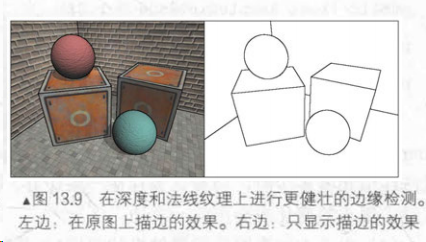
再谈边缘检测
在之前,我们使用sobel算子进行边缘卷积检测。现在我们可以获取深度纹理和法线纹理了,显然这些纹理对边缘的颜色差异描述更明显了。因此我们可以实现更加强大的边缘检测效果:
我们将使用Roberts算子,其本质是计算左上角和右下角的差值,若超过阈值则认为它们之间存在边界。
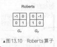
实际上从这个卷积核的形状来看,不难发现它实际检测正负方向四十五度的像素梯度是比较强力的。下面我们选用Gx来检测正方向四十五度的像素变换。
C#:
using System.Collections;
using System.Collections.Generic;
using UnityEngine;

public class CustomEdgeDetectNormalAndDepth : CustomPostEffectsBase
{
	public Shader edgeDetectShader;
	private Material edgeDetectMaterial = null;
	public Material material {
		get {
			edgeDetectMaterial = CheckShaderAndCreateMaterial(edgeDetectShader, edgeDetectMaterial);
			return edgeDetectMaterial;
		}
	}

	[Range(0.0f, 1.0f)]
	public float edgesOnly = 0.0f;

	public Color edgeColor = Color.black;

	public Color backgroundColor = Color.white;

	public float sampleDistance = 1.0f;

	public float sensitivityDepth = 1.0f;

	public float sensitivityNormals = 1.0f;

	void OnEnable() {
		GetComponent<Camera>().depthTextureMode |= DepthTextureMode.DepthNormals;
	}

	// 只对不透明物体产生影响
	[ImageEffectOpaque]
	override protected void OnRenderImage (RenderTexture source, RenderTexture destination)
	{
		if (material != null) {
			material.SetFloat("_EdgeOnly", edgesOnly);
			material.SetColor("_EdgeColor", edgeColor);
			material.SetColor("_BackgroundColor", backgroundColor);
			material.SetFloat("_SampleDistance", sampleDistance);
			material.SetVector("_Sensitivity", new Vector4(sensitivityNormals, sensitivityDepth, 0.0f, 0.0f));

			Graphics.Blit(source, destination, material);
		} else {
			Graphics.Blit(source, destination);
		}
	}
}
Shader:
Shader "Custom/EdgeDetectNormalAndDepth_Copy"
{
    Properties
    {
		_MainTex ("Base (RGB)", 2D) = "white" {}
		_EdgeOnly ("Edge Only", Float) = 1.0
		_EdgeColor ("Edge Color", Color) = (0, 0, 0, 1)
		_BackgroundColor ("Background Color", Color) = (1, 1, 1, 1)
		_SampleDistance ("Sample Distance", Float) = 1.0
		_Sensitivity ("Sensitivity", Vector) = (1, 1, 1, 1)
    }
    SubShader
    {
		CGINCLUDE

		#include "UnityCG.cginc"

		sampler2D _MainTex;
		half4 _MainTex_TexelSize;
		fixed _EdgeOnly;
		fixed4 _EdgeColor;
		fixed4 _BackgroundColor;
		float _SampleDistance;
		half4 _Sensitivity;

		sampler2D _CameraDepthNormalsTexture;

		struct v2f {
			float4 pos : SV_POSITION;
			// 一维用于保存uv坐标,其余四维用于采样
			half2 uv[10]: TEXCOORD0;
		};
		v2f vert(appdata_img v) {
			v2f o;
			o.pos = UnityObjectToClipPos(v.vertex);

			half2 uv = v.texcoord;
			o.uv[0] = uv;

			#if UNITY_UV_STARTS_AT_TOP
			if(_MainTex_TexelSize.y < 0)
				uv.y = 1- uv.y;
			#endif

			// 虽然不知道书中的采样方式为什么可以,但一定有它的数学原理
			/* 采样对角四宫格构成的矩阵似乎就能计算边缘值了
			o.uv[1] = uv + _MainTex_TexelSize.xy * half2(1,1) * _SampleDistance;
			o.uv[2] = uv + _MainTex_TexelSize.xy * half2(-1,-1) * _SampleDistance;
			o.uv[3] = uv + _MainTex_TexelSize.xy * half2(-1,1) * _SampleDistance;
			o.uv[4] = uv + _MainTex_TexelSize.xy * half2(1,-1) * _SampleDistance;
			*/
			// 此处我打算用九宫格采样周边像素依次计算,计算结果是一模一样的
			o.uv[1] = uv + _MainTex_TexelSize.xy * half2(-1,-1) * _SampleDistance;
			o.uv[2] = uv + _MainTex_TexelSize.xy * half2(0,-1) * _SampleDistance;
			o.uv[3] = uv + _MainTex_TexelSize.xy * half2(1,-1) * _SampleDistance;
			o.uv[4] = uv + _MainTex_TexelSize.xy * half2(-1,0) * _SampleDistance;
			o.uv[5] = uv + _MainTex_TexelSize.xy * half2(0,0) * _SampleDistance;
			o.uv[6] = uv + _MainTex_TexelSize.xy * half2(1,0) * _SampleDistance;
			o.uv[7] = uv + _MainTex_TexelSize.xy * half2(-1,1) * _SampleDistance;
			o.uv[8] = uv + _MainTex_TexelSize.xy * half2(0,1) * _SampleDistance;
			o.uv[9] = uv + _MainTex_TexelSize.xy * half2(1,1) * _SampleDistance;

			return o;
		}
		// 检查卷积核对象像素深度或法线值是否相同
		half CheckSame(half4 center, half4 sample) {
			half2 centerNormal = center.xy;
			float centerDepth = DecodeFloatRG(center.zw);
			half2 sampleNormal = sample.xy;
			float sampleDepth = DecodeFloatRG(sample.zw);

			// 此处并未对法线解码,因为只需要计算差异度即可
			half2 diffNormal = abs(centerNormal - sampleNormal) * _Sensitivity.x;
			int isSameNormal = (diffNormal.x + diffNormal.y) < 0.1;

			float diffDepth = abs(centerDepth - sampleDepth) * _Sensitivity.y;
			int isSameDepth = diffDepth < 0.1 * centerDepth;

			// 若深度和法线值存在相同则返回0,说明是边缘,否则若都不相同则返回1
			return isSameNormal * isSameDepth ? 1.0 : 0.0;
		}
		fixed4 fragRobertsCrossDepthAndNormal(v2f i) : SV_Target {
			half4 sample1 = tex2D(_CameraDepthNormalsTexture, i.uv[1]);
			half4 sample2 = tex2D(_CameraDepthNormalsTexture, i.uv[2]);
			half4 sample3 = tex2D(_CameraDepthNormalsTexture, i.uv[3]);
			half4 sample4 = tex2D(_CameraDepthNormalsTexture, i.uv[4]);
			half4 sample5 = tex2D(_CameraDepthNormalsTexture, i.uv[5]);
			half4 sample6 = tex2D(_CameraDepthNormalsTexture, i.uv[6]);
			half4 sample7 = tex2D(_CameraDepthNormalsTexture, i.uv[7]);
			half4 sample8 = tex2D(_CameraDepthNormalsTexture, i.uv[8]);
			half4 sample9 = tex2D(_CameraDepthNormalsTexture, i.uv[9]);


			half edge = 1.0;

			// 判断是否为边缘,edge=0为边缘,1则不是
			/*
			// Gx卷积核
			edge *= CheckSame(sample1, sample2);
			// Gy卷积核
			edge *= CheckSame(sample3, sample4);
			 */

			// Gx卷积核
			edge *= CheckSame(sample1, sample5);
			edge *= CheckSame(sample2, sample6);
			edge *= CheckSame(sample4, sample8);
			edge *= CheckSame(sample5, sample9);

			// Gy卷积核
			edge *= CheckSame(sample2, sample4);
			edge *= CheckSame(sample3, sample5);
			edge *= CheckSame(sample5, sample7);
			edge *= CheckSame(sample6, sample8);


			//	混合边缘与主纹理
			fixed4 withEdgeColor = lerp(_EdgeColor, tex2D(_MainTex, i.uv[0]), edge);
			// 混合边缘与自设背景色
			fixed4 onlyEdgeColor = lerp(_EdgeColor, _BackgroundColor, edge);

			// 混合边缘计算后的纹理和背景色
			return lerp(withEdgeColor, onlyEdgeColor, _EdgeOnly);
		}

		ENDCG

		Pass {
			ZTest Always
			Cull Off
			ZWrite Off

			CGPROGRAM

			#pragma vertex vert
			#pragma fragment fragRobertsCrossDepthAndNormal

			ENDCG
		}
    }
    FallBack "Diffuse"
}


 1987
1987


 被折叠的 条评论
为什么被折叠?
被折叠的 条评论
为什么被折叠?
 到【灌水乐园】发言


