


目录(附DEMO,可下载,讲解过程超详细)
【S32K3_MCAL从入门到精通】合集:
S32K3_MCAL从入门到精通 https://blog.csdn.net/qfmzhu/category_12519033.html
<--返回「Autosar_MCAL高阶配置」专栏主页-->
1 下载FREERTOS RTD
打开链接S32K汽车通用MCU | NXP 半导体,网页往下翻,找到“软件”这一栏中的S32K3 Reference Software,单击其右侧的下载。
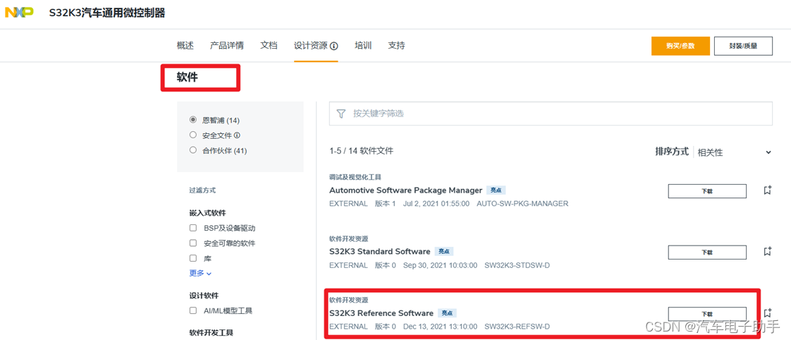
图1-1
在弹出的网页中,选择Automotive SW - S32K3 - FreeRTOS;
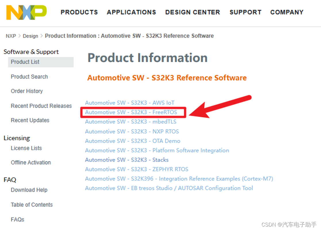
图1-2
在刷新的网页中,选择SW32K3_FreeRTOS_10.5.1_3.1.0_D2304;
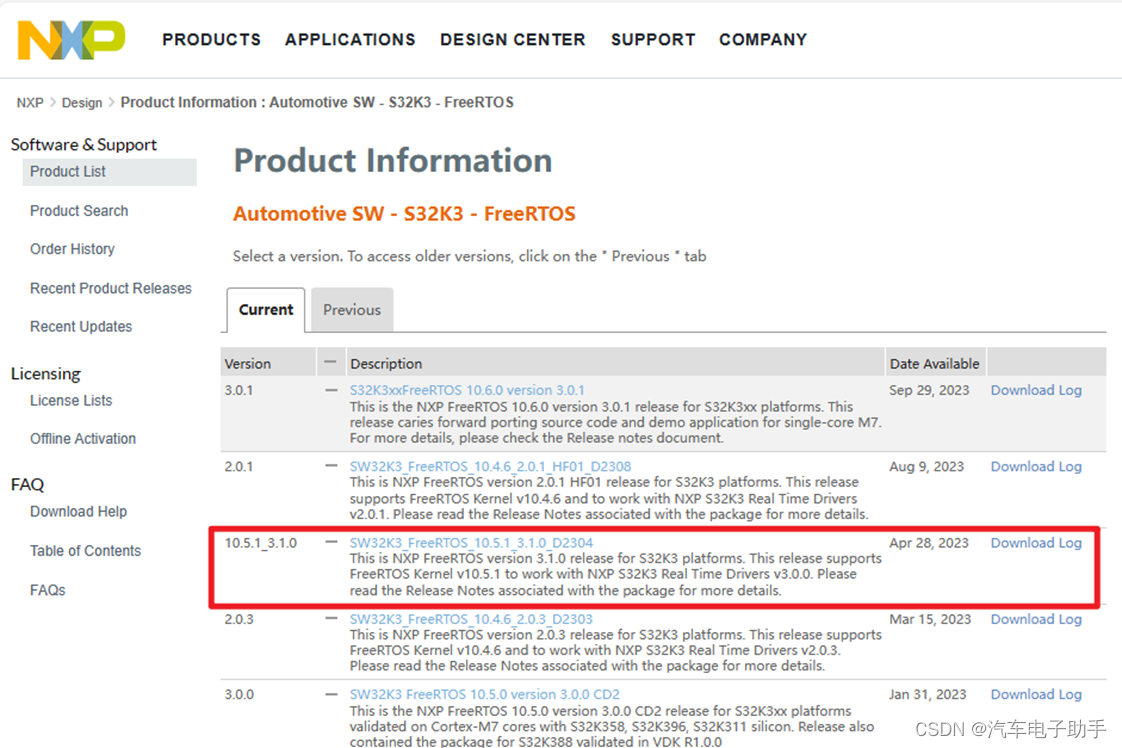
图1-3
在刷新的网页中,单击SW32K3_FreeRTOS_10_5_1_UOS_3_1_0_DS_updatesite_D2304.zip,下载该RTD。

图1-4
1.1 安装FREERTOS RTD
参考博文【S32K3环境搭建】-0.3-S32DS安装实时驱动RTD(Real-Time Driver)https://blog.csdn.net/qfmzhu/article/details/134843314的第2.2章节,安装FreeRTOS RTD:SW32K3_FreeRTOS_10_5_1_UOS_3_1_0_DS_updatesite_D2304.zip。
FreeRTOS RTD(Real-Time Driver)安装后的效果:在S32DS Extensions and Updates中,你会看到安装好的FreeRTOS RTD。
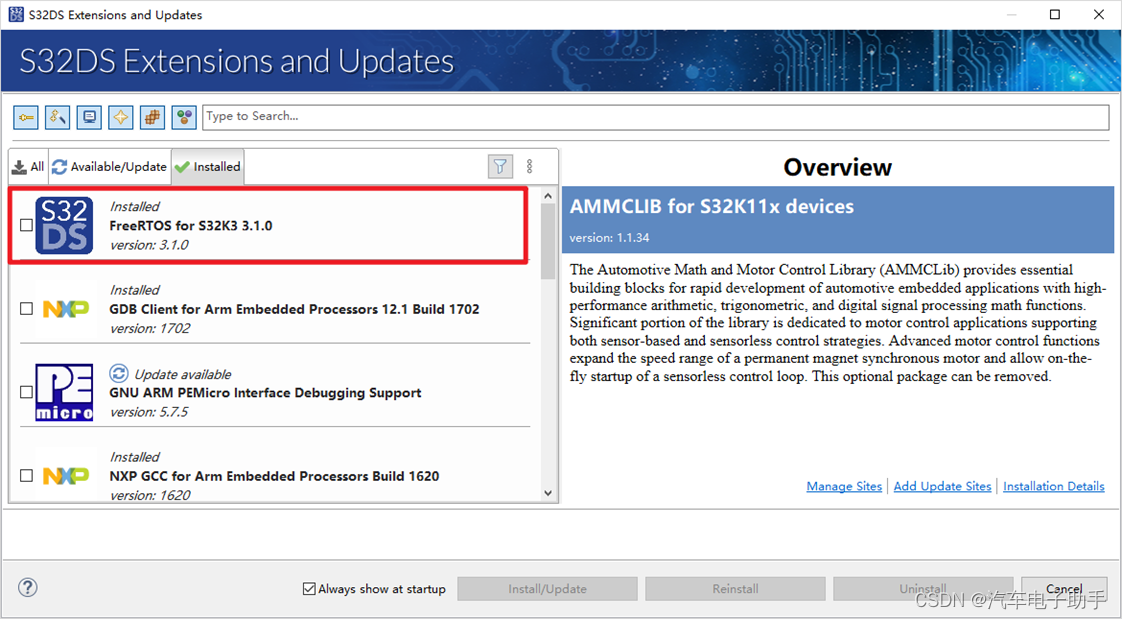
图1-5
2 确认S32DS已安装的AUTOSAR RTD
S32K3 RTD AUTOSAR R21-11 Version 3.0.0
S32K3xx RTD AUTOSAR R21-11 Version 3.0.0
S32K3xx development package V3.5.8
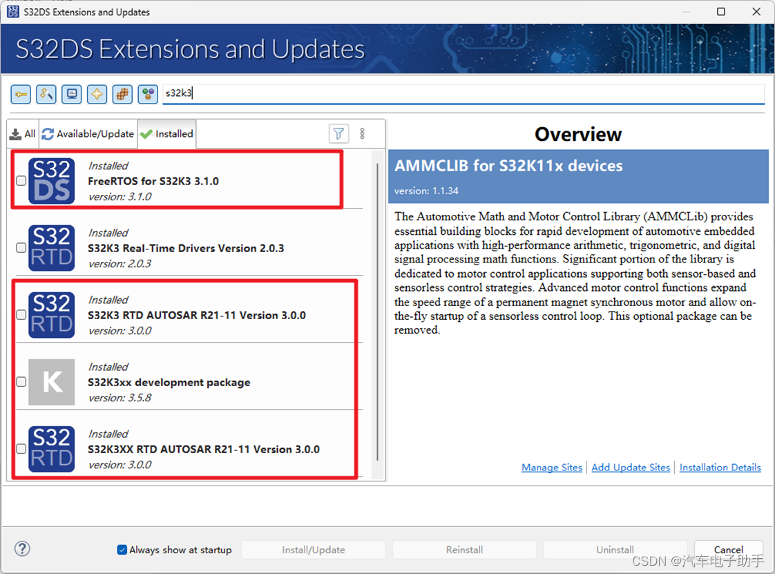
图2-1
3 基于S32K3创建&配置FREERTOS工程
在S32DS的Project Explorer中,鼠标右键,在其上下文中依次选择:New -- > S32DS Project from Example;
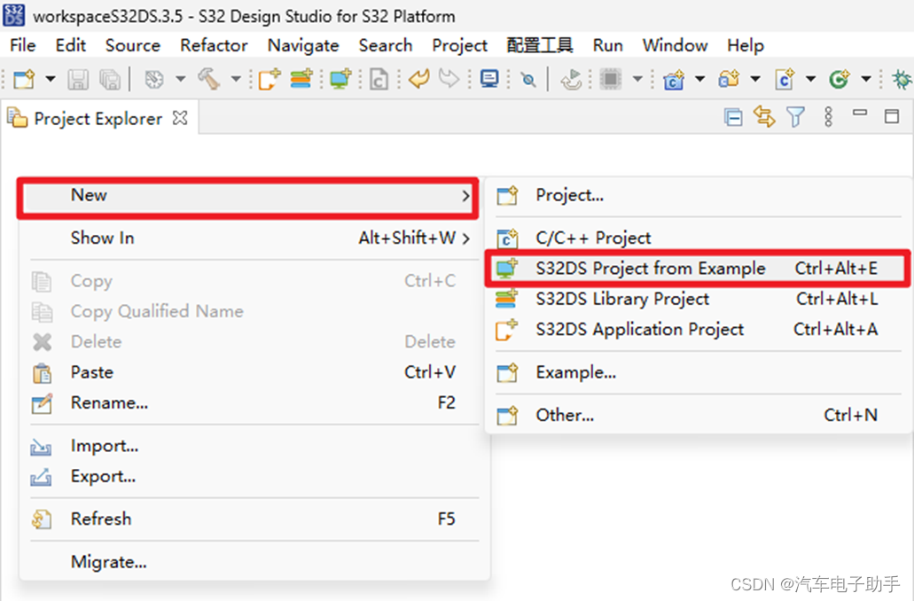
图3-1
在弹出的Create S32DS Project from Example对话框中,根据自己当前使用的MCU芯片型号进行选择,这里以FreeRTOS_Toggle_Led_Example_S32K312为例,单击Finish。
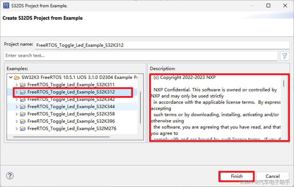
图3-2
注意Description中,关于该DEMO的介绍,其中包含了一些重要信息:
  (c) Copyright 2022-2023 NXP

  NXP Confidential. This software is owned or controlled by NXP and may only be used strictly
  in accordance with the applicable license terms.  By expressly accepting
  such terms or by downloading, installing, activating and/or otherwise using
  the software, you are agreeing that you have read, and that you agree to
  comply with and are bound by, such license terms.  If you do not agree to
  be bound by the applicable license terms, then you may not retain,
  install, activate or otherwise use the software.

  This file contains sample code only. It is not part of the production code deliverables.
========================================================================

1. Example Description
    Led D79-(Motherboard) - toggled using Clock, Siul2_Dio, Siul2_Port drivers and FreeRTOS.
    1.1 The application software functionality
            The application uses 2 tasks SendTask and ReceiveTask. If ReceiveTask receives exactly Semaphore sent by SendTask, it will change led status.
            The application uses Siul2_Port_Ip_Init to initialize the pins and Clock_Ip_Init to initialize the clock sources.

2. Installation steps
    2.1 Hardware installation
        2.1.1 Supported boards
            - XS32K3X2CVB-Q172 PCB 48307 RevX1 SCH RevA (Daughter card)
            - X-S32K3XXX-MB PCB 47386 RevA SCH RevA (Motherboard)
            - S32K312EVB-Q172 50892 PCB RevA SCH RevB (EVB board)
        2.1.2 Connections
            A wire connection is required between the following:
                - pin J290.4  (PTA_1 - gpio LED blink) to pin J290.3 (Led D79)-(Motherboard).
                - PTA29 is controlling the LED_RED in S32K312EVB-Q172 EVB board - when HIGH LED is ON when LOW LED is OFF.
        2.1.3 Debugger
            The Pemicro must be connected to J32 10-pin JTAG Cortex Debug connector.
    2.2 Software installation
        2.2.1 Importing the S32 Design Studio project
            After opening S32 Design Studio, go to "File -> New -> S32DS Project From Example" and select this example. Then click on "Finish".
            The project should now be copied into your current workspace.

3. Generating, building and running the example application
    3.1 Generating the S32 configuration
        Before running the example a configuration needs to be generated. First go to Project Explorer View in S32 DS and select the current project.
        Select the "S32 Configuration Tool" menu then click on the desired configuration tool (Pins, Cocks, Peripherals etc...).
        Clicking on any one of those will generate all the components. Make the desired changes(if any) then click on the "S32 Configuration Tool->Update Code" button.
    3.2 Compiling the application
        Select the configuration to be built: RAM (Debug_RAM), or FLASH (Debug_FLASH) by left clicking on the downward arrow corresponding to the build button in eclipse.
        Wait for the build action to be completed before continuing to the next step. Check the compiler console for error messages; upon completion, the *.elf binary file
        should be created.
    3.3 Running the application on the board
        3.3.1 Running with P&E micro
            Go to Run and select Debug Configurations. There will be a debug configuration for this project:

            Configuration Name                  Description
            -------------------------------     -----------------------
            $(example)_Debug_FLASH_PNE          Debug the FLASH configuration using PEMicro Debugging
            $(example)_Debug_RAM_PNE            Debug the RAM configuration using PEMicro Debugging

            Select the desired debug configuration and click on Debug. Now the perspective will change to the Debug Perspective.
            Use the controls to control the program flow.
        3.3.2 Running with Lauterbach
            To execute the example application load the executable file to the evaluation board using the Lauterbach debugger and the debug_t32/run.cmm script.
            Open debug_t32/run.cmm file in text editor if want to change target memory please change the values of &load_to and &elf_file.
            Run this script using T32 Lauterbach debugger after making the changes.
在Project Explorer中显示了S32K312的FREERTOS工程的文件结构,这里显然缺失了很多,下面我们一一配置。
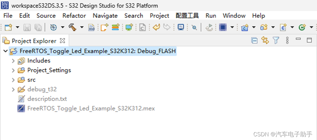
图3-3
3.1 选择SDKs
在S32DS的Project Explorer中,选中工程名称FreeRTOS_Toggle_Led_Example_S32K312,鼠标右键,在其上下文中依次选择Properties;
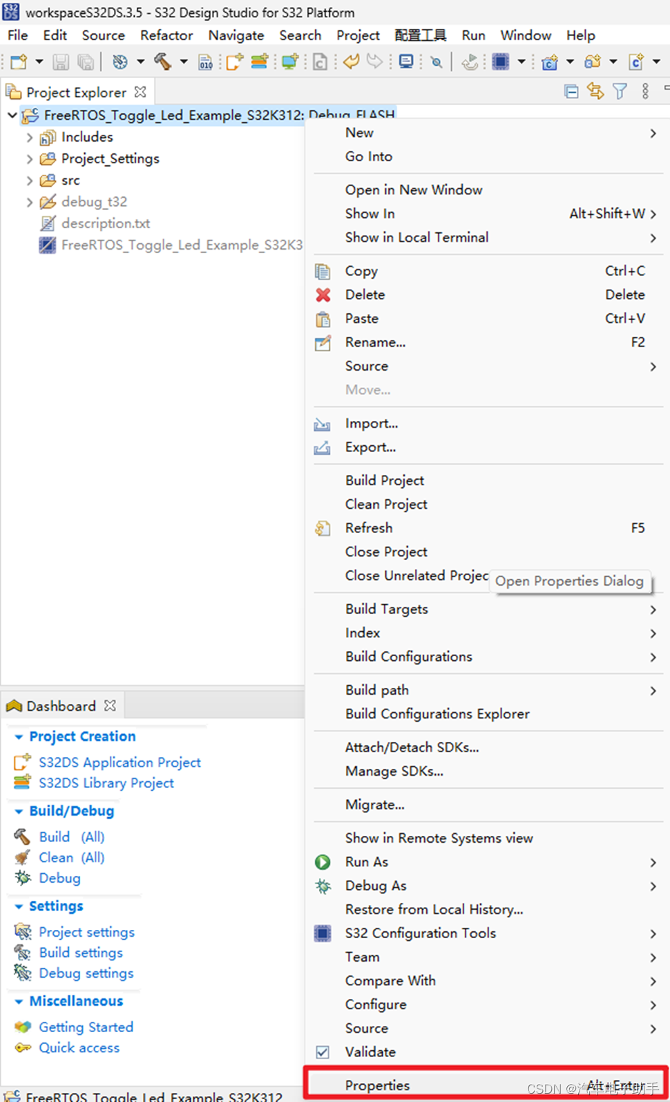
图3-4
在弹出的Properties对话框中,选择SDKs后,选择Restore;
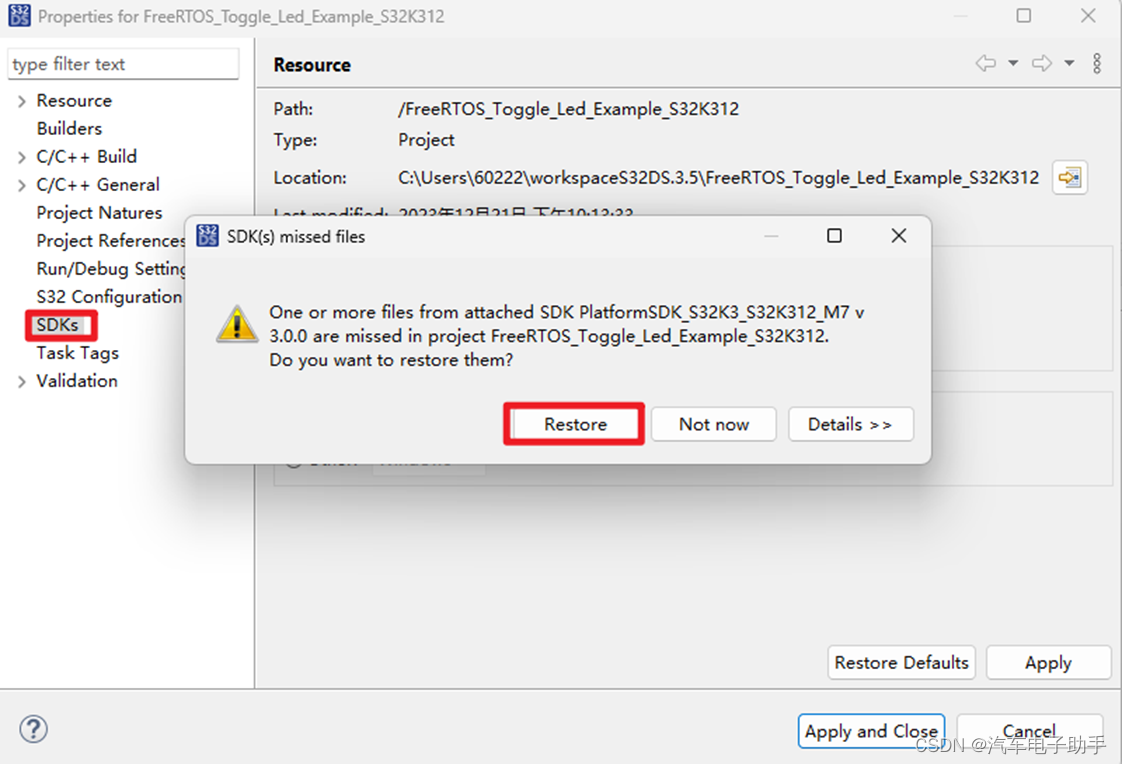
图3-5
PlatformSDK_S32K3_2022_03_S32K312_M7对应AUTOSAR版本:S32K3 Real-Time Drivers Version 2.0.3;
PlatformSDK_S32K3_S32K312_M7对应AUTOSAR版本:S32K3 RTD AUTOSAR R21-11 Version 3.0.0;
“加号”所在位置,表示该工程目前使用AUTOSAR RTD。这里我们默认高版本的V3.0.0,单击Apply and Close;
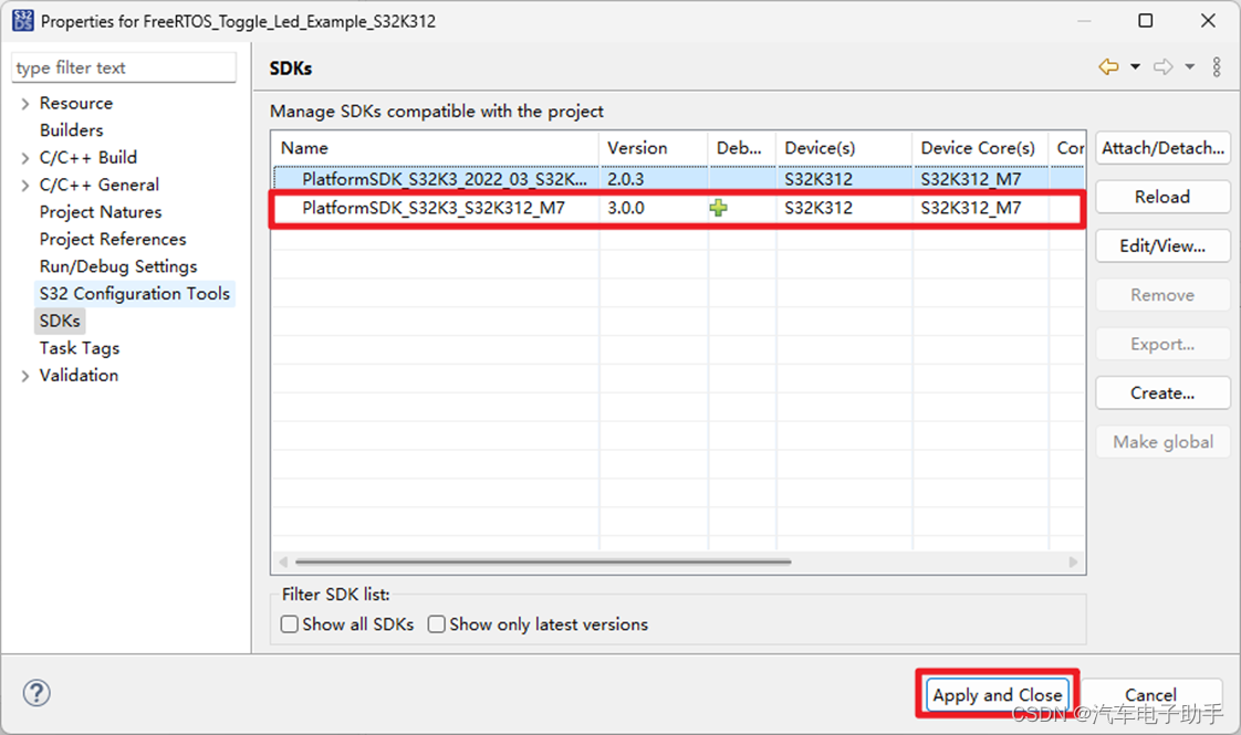
图3-6
在Project Explorer中,工程FreeRTOS_Toggle_Led_Example_S32K312,多了RTD,board和generate文件夹。
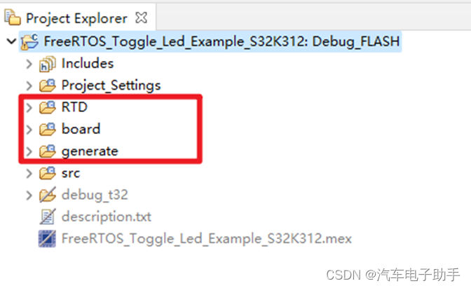
图3-7
3.2 增加FreeRTOS模块
双击mex文件,或者单击工具栏中的Open S32 Configuration Tools;
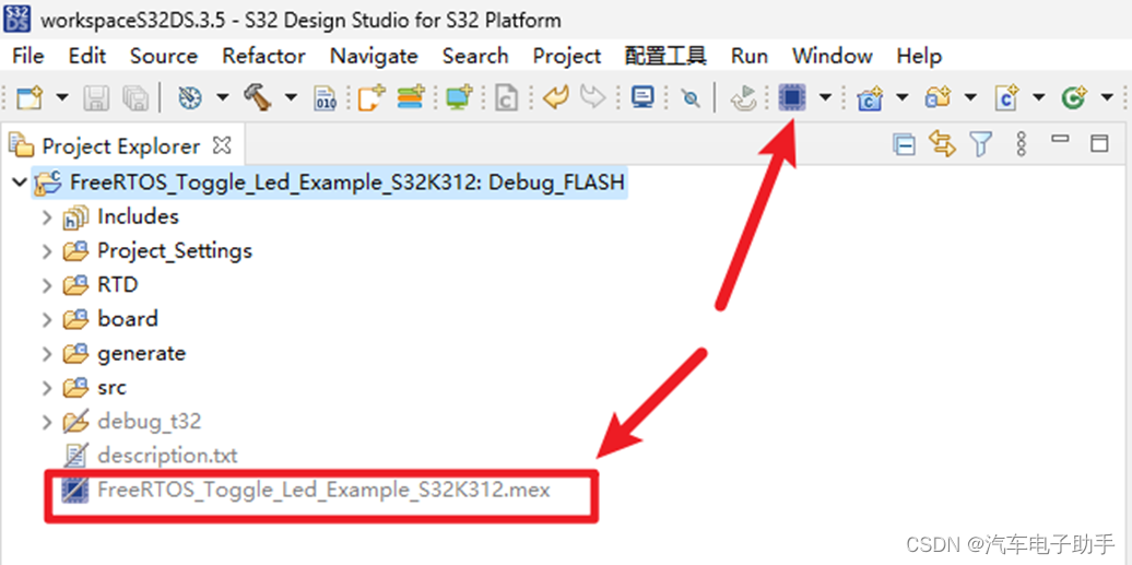
图3-8
在外设中,查看OS层中,是否已经添加了FreeRTOS模块。
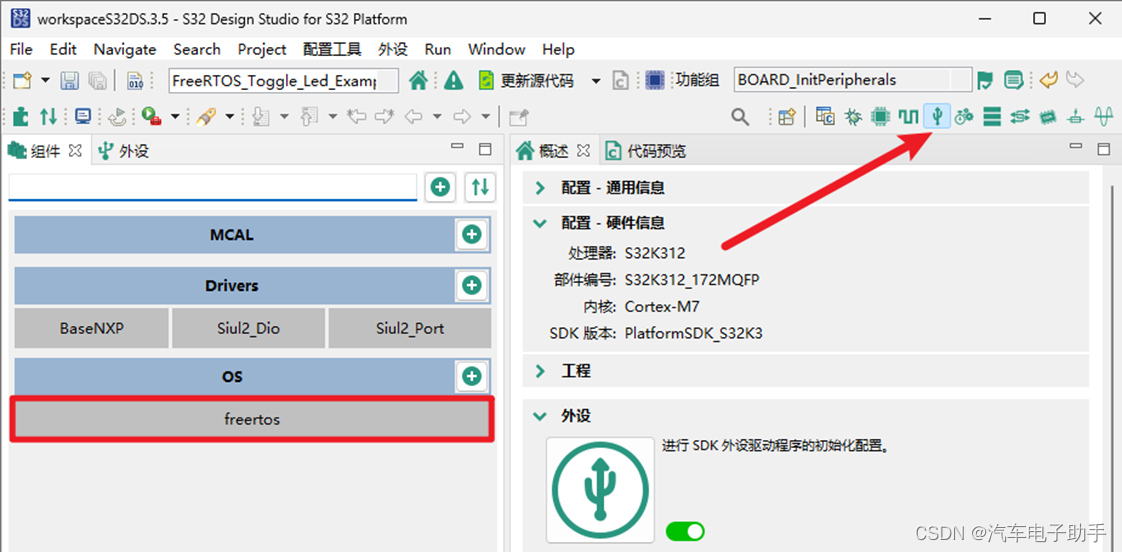
图3-9
3.3 修改MCU芯片封装
在Pins引脚中,根据实际使用MCU封装情况,切换封装。
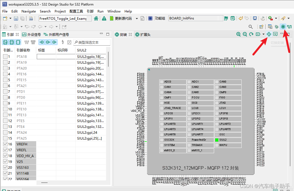
图3-10
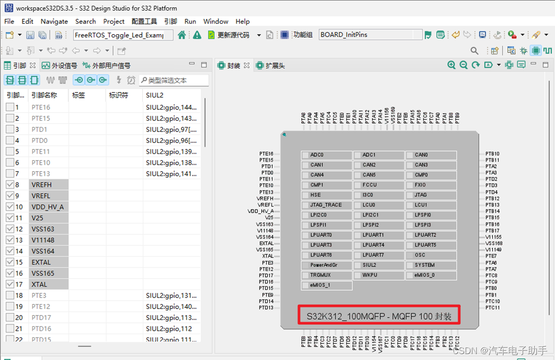
图3-11
3.4 配置GPIO
在该FreeRTOS工程中,默认将PTA1和PTA29配置成了输出,详见图3-2中的Description。可根据您的PCB/开发板实际情况,在Pins引脚中,进行调整和适配。我们这里将其调整为PTB9和PTB10。
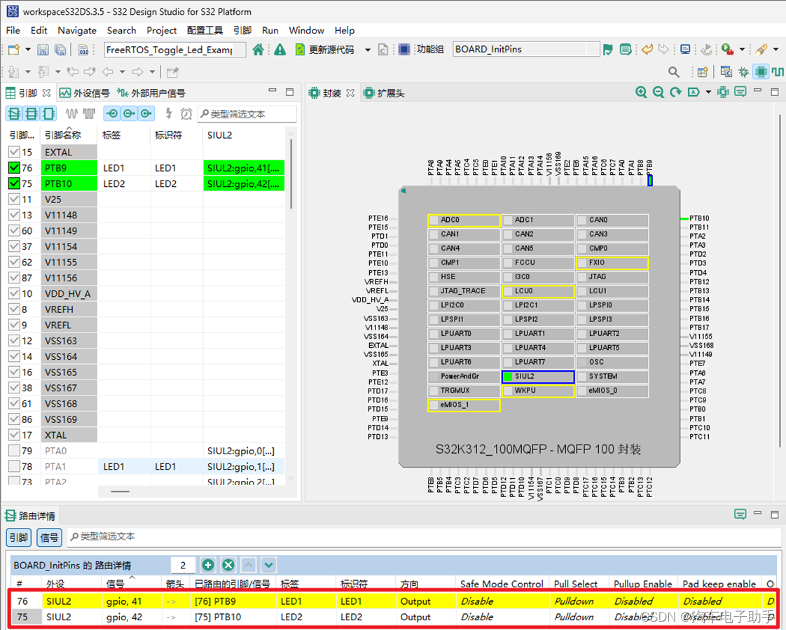
图3-12
3.5 修改HSE CLK时钟
在Clocks的时钟显示图中,修改HSE CLK的分频器,将其从120MHz修改为60MHz。
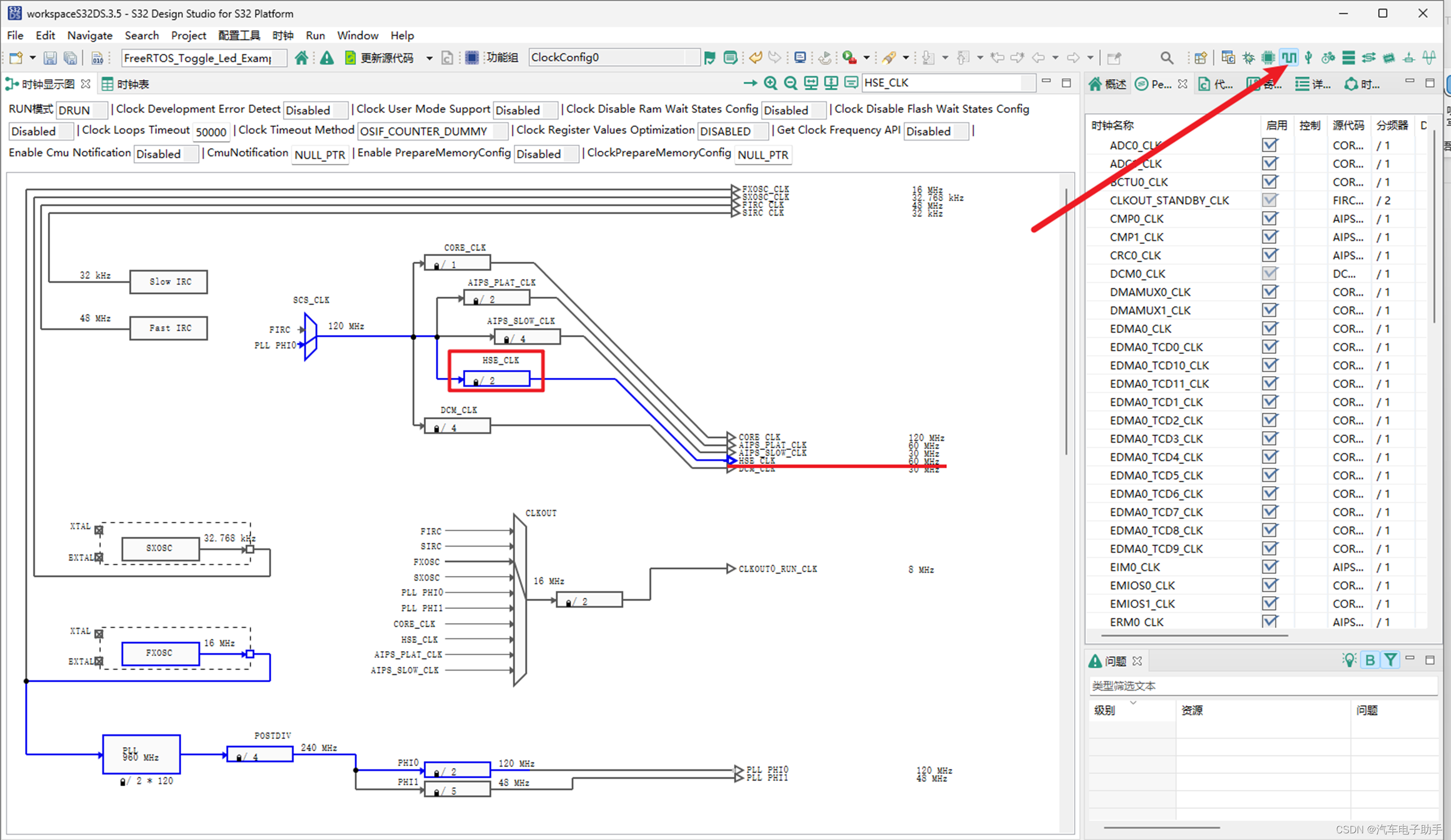
图3-12
3.5 更新代码
配置完成后,单击工具栏中更新代码,将配置生成代码。
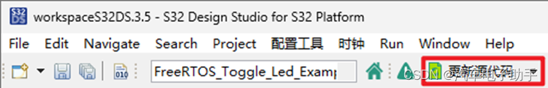
图3-13
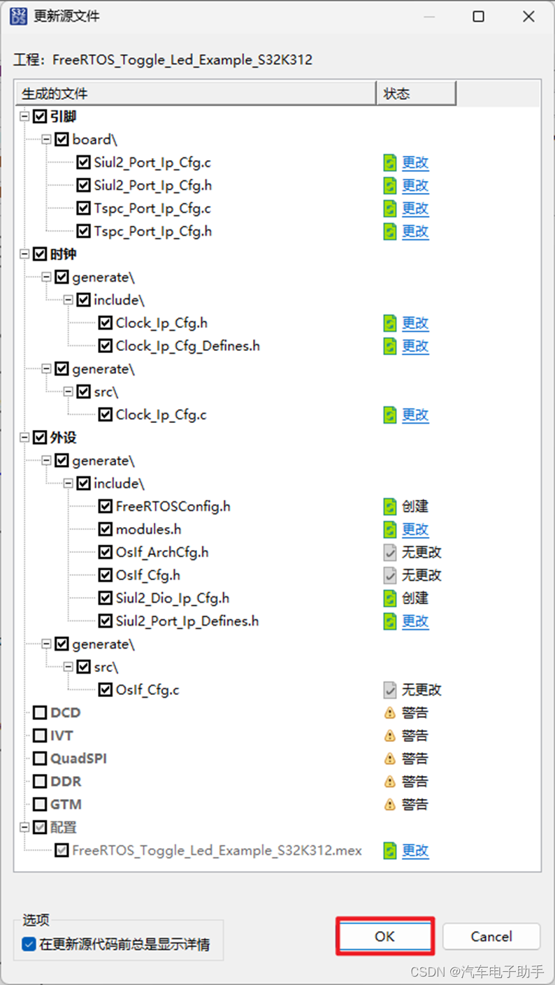
图3-14
配置完成后,在Project Explorer中,显示了FreeRTOS_Toggle_Led_Example_S32K312工程完整的结构。
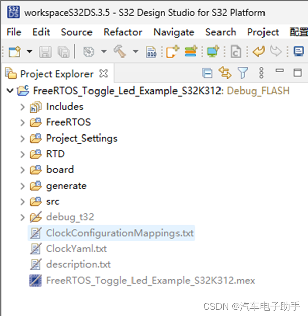
图3-15
4 main函数解读
在main函数中,使用xTaskCreate创建了两个Task: SendTask和ReceiveTask。在ReceiveTask函数中间隔Siul2_Dio_Ip_TogglePins周期拉高拉低PTB9和PTB10。
/* Including necessary configuration files. */
#include "Clock_Ip.h"
#include "FreeRTOS.h"
#include "task.h"
#include "semphr.h"
#include "Siul2_Port_Ip.h"
#include "Siul2_Dio_Ip.h"

#define main_TASK_PRIORITY                ( tskIDLE_PRIORITY + 2 )

SemaphoreHandle_t sem_handle;
volatile BaseType_t testResult = 0x33U;

/**
* @brief        SendTask is used to give the semaphore
* @details      SendTask give the semaphore every 1 second
*/
void SendTask( void *pvParameters )
{
    (void)pvParameters;
    BaseType_t operation_status;

    for( ;; )
    {
        operation_status = xSemaphoreGive(sem_handle);
        configASSERT(operation_status == pdPASS);
        /* Not very exciting - just delay... */
        vTaskDelay(pdMS_TO_TICKS(1000));
    }
}

/**
* @brief        ReceiveTask get the semaphore and toggle pins
* @details      ReceiveTask try to get the semaphore with portMAX_DELAY timeout,
*               After receiving the semaphore successfully, the led will be toggle
*               LED1_PIN <-> PTA1
*               LED2_PIN <-> PTA29
*/
void ReceiveTask( void *pvParameters )
{
    (void)pvParameters;
    BaseType_t operation_status;
    BaseType_t count = 0;

    for( ;; )
    {
        operation_status = xSemaphoreTake(sem_handle, portMAX_DELAY);
        configASSERT(operation_status == pdPASS);
        Siul2_Dio_Ip_TogglePins(LED1_PORT, (1 << LED1_PIN));
        Siul2_Dio_Ip_TogglePins(LED2_PORT, (1 << LED2_PIN));
        if(count++ > 10)
        {
            testResult = 0x5AU;
        }
    }
}

/**
* @brief        Main function of the example
* @details      Initializes the used drivers and uses 1 binary Semaphore and
*               2 tasks to toggle a LED.
*/
int main(void)
{
    /* Initialize Clock */
    Clock_Ip_StatusType Status_Init_Clock = CLOCK_IP_ERROR;
    Status_Init_Clock = Clock_Ip_Init(Clock_Ip_aClockConfig);

    if (Status_Init_Clock != CLOCK_IP_SUCCESS)
    {
        while(1); /* Error during initialization. */
    }

    /* Initialize all pins using the Port driver */
    Siul2_Port_Ip_PortStatusType Status_Init_Port = SIUL2_PORT_ERROR;
    Status_Init_Port = Siul2_Port_Ip_Init(NUM_OF_CONFIGURED_PINS0, g_pin_mux_InitConfigArr0);

    if(Status_Init_Port != SIUL2_PORT_SUCCESS)
    {
        while(1); /* Error during initialization. */
    }

    vSemaphoreCreateBinary(sem_handle);
    xTaskCreate( SendTask   , ( const char * const ) "SendTask", configMINIMAL_STACK_SIZE, (void*)0, main_TASK_PRIORITY, NULL );
    xTaskCreate( ReceiveTask, ( const char * const ) "RecTask" , configMINIMAL_STACK_SIZE, (void*)0, main_TASK_PRIORITY + 1, NULL );
    vTaskStartScheduler();

    for( ;; );

    return 0;
}
5 附:FreeRTOS DEMO
该博文,附上了配置好的FreeRTOS DEMO下载链接。
结尾
获取更多“汽车电子资讯”和“工具链使用”,
请关注CSDN博客“汽车电子助手”,做您的好助手。


 1015
1015

 被折叠的 条评论
为什么被折叠?
被折叠的 条评论
为什么被折叠?
 到【灌水乐园】发言


