


Vector CANoe CAPL系列相关文章导览,下面链接可直接跳转
Vector CANoe VT System系列板卡文章导览,下面链接可直接跳转
引言
本章节继续聊VT2816A模拟板卡的功能,板卡详细内容见VT_System_Manual_EN.pdf,内容为个人理解,如有错误,欢迎指正
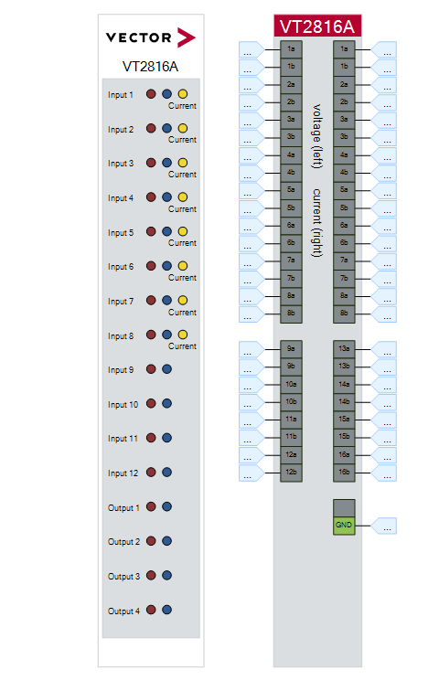
The VT2816A provides 12 analog measuring channels and 4 analog output channels.
The 12 input channels are used for voltage measurement. Alternatively, current can be measured on the first 8 channels using an integrated shunt resistor.
A voltage can be output on 4 additional independent channels.
The inputs and outputs of the VT2816A can be used universally. The module can be connected directly to inputs and outputs of control units. However, the module can also be used to measure or control other analog signals, such as are needed for control in a test bed, for example.
又是一段简介,说了啥呢
- VT2816A提供12个模拟测量通道和4个模拟输出通道。
- 12个测量通道用来做电压测量,只有前8个可以用来测量电流
- 4个输出通道用来做电压输出
- 输入输出通道可以通用
- 模块可以直接连接到控制单元的输入输出通道
- 模块也可以用来测量或控制其他模拟信号,例如在测试架上需要控制时用到的模拟信号
VT2816A FPGA
手上暂时没有这个可编程板卡,等遇到了再补充
前后面板图
Usage
Basic Connection Scheme
Connection for voltage measurement
接线方式:每个通道的a接要测量的电压,b接参考电位,也就是a所接的地
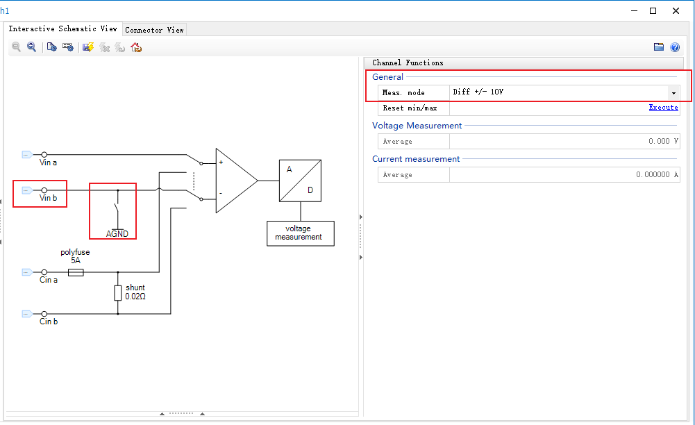
Differential measuring mode - 差分

差分模式下line a和line b都要接
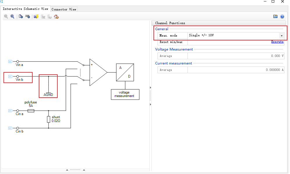
Single-ended measuring mode - 单端

单端模式下,line b 内部接到AGND,因此,line b 不必再接线
注意
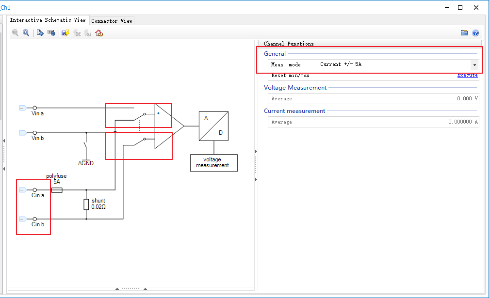
只有channel 1-8 可以用来做电流测量,channel 9-12 只能用来做电压测量
Connection for current measurement

注意电流流向接线,否则你会得到相反的值!!!
Connection for voltage output
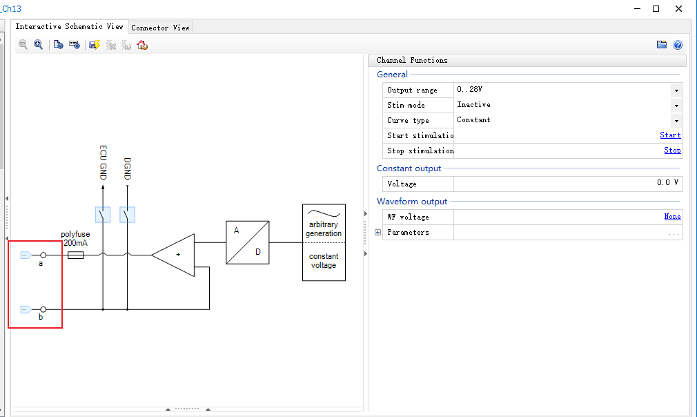
见上图,可以通过继电器来控制选择输出地是ECU GND还是DGND还是 line b
Measurement - 模拟量测量
Voltage Measurement
和其他板卡一样,这也是Vector工具链的特色,基于variables来交互,通过variables可以获取瞬时值、平均值、均方根值、最大/最小值。
Current Measurement
同上
具体如何配置操作,参见这里有配置操作参考
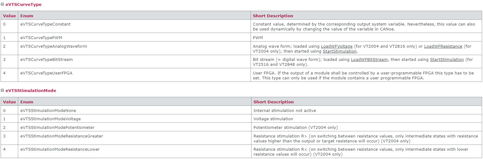
Voltage Stimulation - 模拟量(电压)输出
通过脚本来控制选择模式和type,具体内容后面将CAPL脚本会介绍
接插件定义
看手册8.4章节
Technical Data VT2816A
手册中都有,这里再贴一下
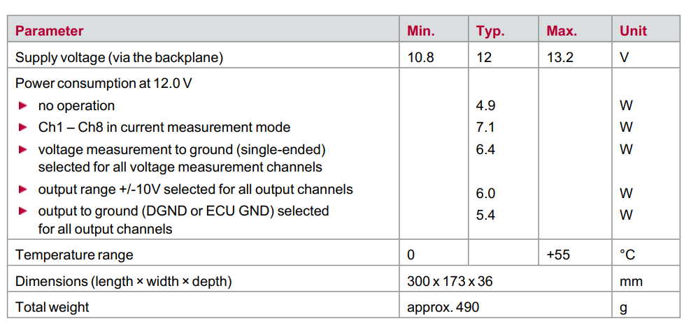
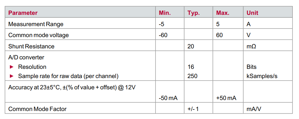
General
Voltage Measurement
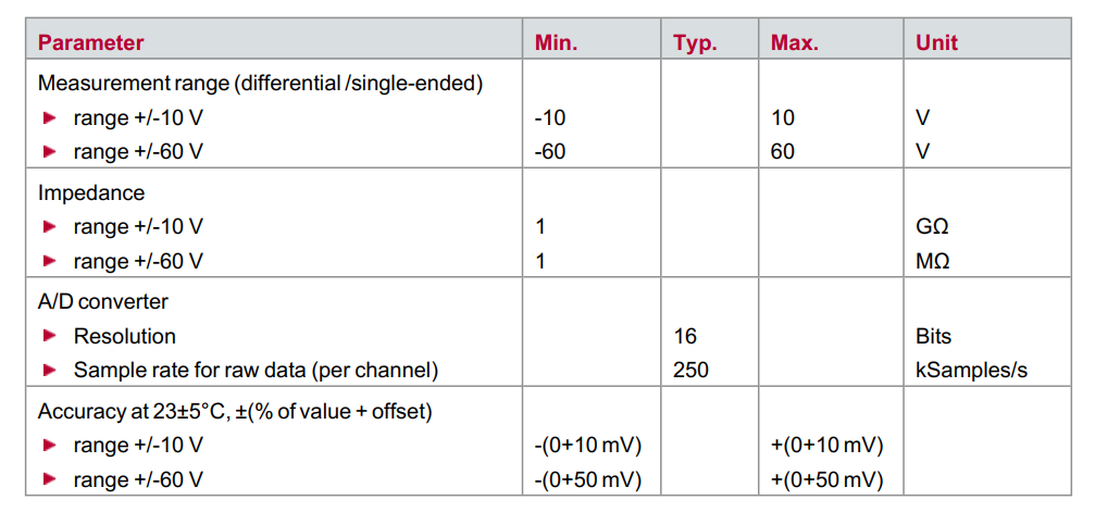
精度取决于两个部分(值的百分比 + 偏移),和VT2516A板卡类似
Current Measurement
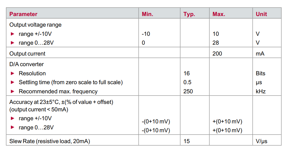
Voltage Stimulation
CAPL实例
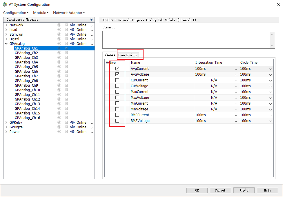
VT System Configuration
连接板卡,不知道咋操作的,看这里里面有详细说明
VT System Control
差分测量配置
单端测量配置
电流测量配置
电压输出配置

以上,所有模式配置均可忽略,后面通过CAPL脚本来切换模式
CAPL函数库
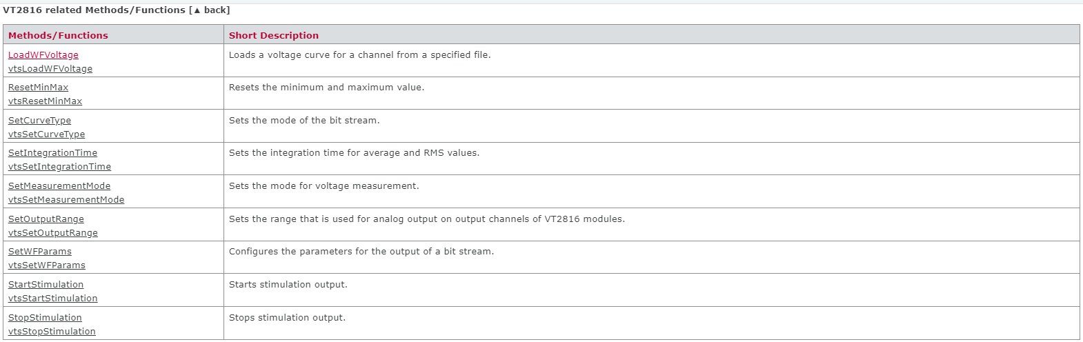
(搜索这个文件CAPLfunctionsVTSystemOverview.htm,有详细介绍,包括函数使用示例等)
System Variables
system-defined
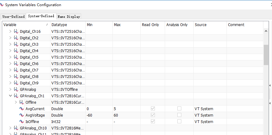
前面System Configurations里面勾选了哪些,就会注册成系统变量,在这里显示出来
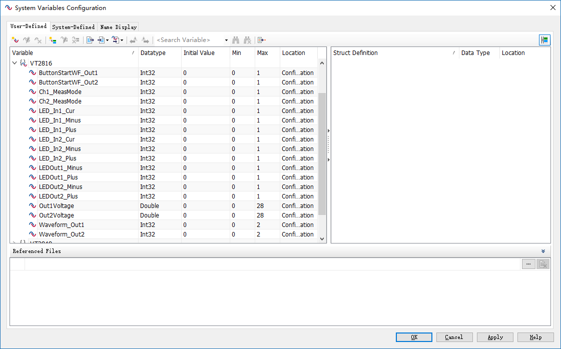
创建variables
根据需要创建如下variables以便于后续panel和capl进行调用
制作Panel
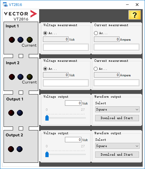
- Voltage Measurement
- Current Measurement
- Voltage Output
- Waveform Output
编写CAPL脚本
Measurement Mode
on sysvar sysvar::VT2816::Ch1_MeasMode
{
    // according to select radio button on the panel
    if(@this == 0) // Voltage measurement
    {
        sysvar::VTS::GPAnalog_Ch1.SetMeasurementMode(1);
        // Led state on the panel
        @sysvar::VT2816::LED_In1_Cur = 0;
    }
    else // Current measurement
    {
        sysvar::VTS::GPAnalog_Ch1.SetMeasurementMode(4);
        // Led state on the panel
        @sysvar::VT2816::LED_In1_Minus = 0;
        @sysvar::VT2816::LED_In1_Plus = 0;
        @sysvar::VT2816::LED_In1_Cur = 1;
    }
}
Voltage Output
on sysvar sysvar::VT2816::Out1Voltage
{
  // Set curve type constant value
  sysvar::VTS::GPAnalog_Ch13.SetCurveType(0);

  // Set voltage
  @sysvar::VTS::GPAnalog_Ch13::Voltage = @this;

  // Set the LED
  @sysvar::VT2816::LEDOut1_Plus = (@this > 0);
}
Waveform Output
提前准备好几个waveform文件
WFSquare.txt
0; 15
5; 15
WFSawtooth.txt
0.0000
0.1563
0.3125
0.4688
0.6250
0.7813
0.9375
1.0938
1.2500
1.4063
1.5625
1.7188
1.8750
2.0313
2.1875
2.3438
2.5000
2.6563
2.8125
2.9688
3.1250
3.2813
3.4375
3.5938
3.7500
3.9063
4.0625
4.2188
4.3750
4.5313
4.6875
4.8438
WFSine.txt
2.5000
2.9877
3.4567
3.8889
4.2678
4.5787
4.8097
4.9520
5.0000
4.9520
4.8097
4.5787
4.2678
3.8889
3.4567
2.9877
2.5000
2.0123
1.5433
1.1111
0.7322
0.4213
0.1903
0.0480
0.0000
0.0480
0.1903
0.4213
0.7322
1.1111
1.5433
2.0123
void setWaveformOutput()
{
    if(@sysvar::VT2816::ButtonStartWF_Out1 == 0) return;

    // Choose voltage stimulation and waveform curve type
    sysvar::VTS::GPAnalog_Ch13.SetStimulationMode(1);
    sysvar::VTS::GPAnalog_Ch13.SetCurveType(2);

    // Load waveforms
    if(@sysvar::VT2816::Waveform_Out1 == 0)
        sysvar::VTS::GPAnalog_Ch13.LoadWFVoltage("Waveforms\\WFSquare.txt");
    else if(@sysvar::VT2816::Waveform_Out1 == 1)
        sysvar::VTS::GPAnalog_Ch13.LoadWFVoltage("Waveforms\\WFSawtooth.txt");
    else if(@sysvar::VT2816::Waveform_Out1 == 2)
        sysvar::VTS::GPAnalog_Ch13.LoadWFVoltage("Waveforms\\WFSine.txt");

    // Configure waveform. Parameters:
    // TimeIncrement (time to hold each sample)       = 5ms
    // Pause (pause between two waveform repetitions) = 0s
    // NumberOfRepeats (number of repetitions)        = 0 (unlimited)
    sysvar::VTS::GPAnalog_Ch13.SetWFParams(0.005, 0.0, 0);

    // Output the configured waveform
    sysvar::VTS::GPAnalog_Ch13.StartStimulation();

    // Set the LED
    @sysvar::VT2816::LEDOut1_Plus = 1;
}
编译返回canoe主界面测试,在测试前请先确认接线!!!
项目实例
根据实际工况进行处理,不外乎上面的几种情况,只是和具体项目上的信号功能对应,如有问题,请关注,点赞,收藏,后台私信~~~
当前使用场景也比较单一,文中可能有部分内容未提及,或有误,请指出,谢谢!
公众号
欢迎关注公众号,加入专业技术交流。


 2235
2235


 被折叠的 条评论
为什么被折叠?
被折叠的 条评论
为什么被折叠?
 到【灌水乐园】发言


