


在一些大型项目中,通常需要主处理器与多个单机模块共同工作,并且为了保持时间上的同步,需要主处理器定时向各单机模块发送同步信号,各单机模块在接收到同步信号后,按照1us的时间当量进行计时。
在上述过程中,需要有一个1us的时间当量。
本次内容,使用VHDL语言设计一个模块,该模块用于生成1us的tick信号。其实现代码如下:
----------------------------------------------------------------------------------
-- Company:
-- Engineer:
--
-- Create Date: 2024/12/25 17:54:38
-- Design Name:
-- Module Name: tick_generator - Behavioral
-- Project Name:
-- Target Devices:
-- Tool Versions:
-- Description:
--
-- Dependencies:
--
-- Revision:
-- Revision 0.01 - File Created
-- Additional Comments:
--
----------------------------------------------------------------------------------


library IEEE;
use IEEE.STD_LOGIC_1164.ALL;
use IEEE.STD_LOGIC_UNSIGNED.ALL;

-- Uncomment the following library declaration if using
-- arithmetic functions with Signed or Unsigned values
--use IEEE.NUMERIC_STD.ALL;

-- Uncomment the following library declaration if instantiating
-- any Xilinx leaf cells in this code.
--library UNISIM;
--use UNISIM.VComponents.all;

entity tick_generator is
	generic(
		constant RST_VALID : std_logic := '1';
		constant SCALER_SIZE : integer range 1 to 16 := 7;
		constant IS_TICK : std_logic := '1'	-- '1'tick, scaler = 需要的分频数 - 1, '0'clock,scaler = 需要的分频数/2 - 1
	);
	port(
		clk : in std_logic;
		rst : in std_logic;

		base_tick : in std_logic;
		scaler : in std_logic_vector(SCALER_SIZE - 1 downto 0);

		tick : out std_logic
	);
end tick_generator;

architecture Behavioral of tick_generator is

signal cnt : std_logic_vector(SCALER_SIZE - 1 downto 0);
signal tick_s : std_logic;

begin

	tick <= tick_s;

	DO_TICK : if(IS_TICK = '1') generate
	process(clk, rst)
	begin
		if(rst = RST_VALID) then
			cnt <= (others => '0');
			tick_s <= '0';
		elsif(clk'event and clk = '1') then
			tick_s <= '0';

			if(base_tick = '1') then
				if(cnt >= scaler) then
					cnt <= (others => '0');
					tick_s <= '1';
				else
					cnt <= cnt + '1';
				end if;
			end if;
		end if;
	end process;
	end generate;

	DO_CLOCK : if(IS_TICK = '0') generate
	process(clk, rst)
	begin
		if(rst = RST_VALID) then
			cnt <= (others => '0');
			tick_s <= '0';
		elsif(clk'event and clk = '1') then
			if(base_tick = '1') then
				if(cnt >= scaler) then
					cnt <= (others => '0');
					tick_s <= not tick_s;
				else
					cnt <= cnt + '1';
				end if;
			end if;
		end if;
	end process;
	end generate;

end Behavioral;上述代码中,使用关键字generic定义了三个参数,分别是复位信号的有效值、分频参数的位宽、时钟分频的模式。
针对分频的模式,‘1’代表生成tick信号,高电平占一个时钟周期;‘0’代表生成时钟,占空比为50%。
在端口中依次定义了时钟、复位、基础tikc信号、分频大小以及生成的tick信号。
使用vivado对tick_generator模块进行仿真,仿真代码如下所示:
----------------------------------------------------------------------------------
-- Company:
-- Engineer:
--
-- Create Date: 2024/12/25 17:59:13
-- Design Name:
-- Module Name: tb_tick_generator - Behavioral
-- Project Name:
-- Target Devices:
-- Tool Versions:
-- Description:
--
-- Dependencies:
--
-- Revision:
-- Revision 0.01 - File Created
-- Additional Comments:
--
----------------------------------------------------------------------------------


library IEEE;
use IEEE.STD_LOGIC_1164.ALL;

-- Uncomment the following library declaration if using
-- arithmetic functions with Signed or Unsigned values
--use IEEE.NUMERIC_STD.ALL;

-- Uncomment the following library declaration if instantiating
-- any Xilinx leaf cells in this code.
--library UNISIM;
--use UNISIM.VComponents.all;

entity tb_tick_generator is
--  Port ( );
end tb_tick_generator;

architecture Behavioral of tb_tick_generator is

	component tick_generator is
		generic(
			constant RST_VALID : std_logic := '1';
			constant SCALER_SIZE : integer range 1 to 16 := 7;
			constant IS_TICK : std_logic := '1'	-- '1'tick, scaler = 需要的分频数 - 1, '0'clock,scaler = 需要的分频数/2 - 1
		);
		port(
			clk : in std_logic;
			rst : in std_logic;

			base_tick : in std_logic;
			scaler : in std_logic_vector(SCALER_SIZE - 1 downto 0);

			tick : out std_logic
		);
	end component;

	constant SCALER_10 : std_logic_vector(3 downto 0) := "1001";	-- 9

	signal clk : std_logic;
	signal rst : std_logic;
	signal c_tick_1us : std_logic;
	constant clk_period : time := 100 ns;

begin

	--Tick生成模块例化
	U_TICK_1US : tick_generator
	generic map(
		RST_VALID => '1',
		SCALER_SIZE => SCALER_10'length,
		IS_TICK => '1'
	)
	port map(
		clk => clk,
		rst => rst,

		base_tick => clk,
		scaler => SCALER_10,

		tick => c_tick_1us
	);

	--时钟生成
	clk_10mhz_process : process
	begin
		clk <= '0';
		wait for clk_period/2;
		clk <= '1';
		wait for clk_period/2;
	end process;

	--复位生成
	rst_process : process
	begin
		rst <= '1';
		wait for clk_period*200;
		rst <= '0';
		wait;
	end process;
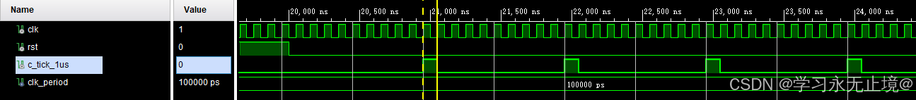
end Behavioral;仿真代码中,对10mhz时钟信号进行分频,产生1us的tick信号。
这种tick信号有一个好处,就是系统可以在10mhz时钟域下使用1us的tick信号进行计时,这个计时器所处的时钟域也是10mhz,避免了10mhz和1mhz跨时钟域的问题。
其仿真波形如下所示:
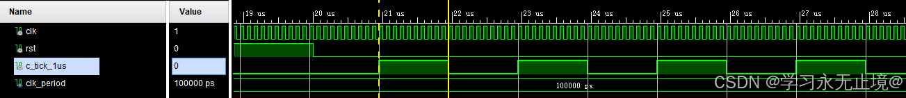
如果例化tick_generator模块的时候,将 IS_TICK => '1'改为IS_TICK => '0',将实现对10mhz时钟的20分频,其结果是产生占空比为50%、时钟频率为5khz的方波。
其仿真波形如下所示:
因此,通过上述tick_generator模块,我们可以实现时钟的各种分频。
总结一下,VHDL模块在设计时,应该尽可能的设置一些可变参数,以便于满足我们对这个模块的重复利用。本次设计中,我们设置三个可变参数,分别对应复位信号的有效值、分频数的位宽、分频的模式。这种设计,基本可以应对任何时钟分频要求。


 1万+
1万+

 被折叠的 条评论
为什么被折叠?
被折叠的 条评论
为什么被折叠?
 到【灌水乐园】发言


