


 文章描述了一个串口接收器的设计,增加了奇偶校验功能,用于检测数据的正确性。接收器采用状态机FSM来识别开始位、读取8位数据、接收奇偶校验位,并进行校验。当接收到的数据字节的奇偶校验正确且停止位正确时,才会触发done信号。提供的代码示例展示了如何实现这个功能,包括状态转换和数据处理过程。
题目:有奇偶校验位的串口接收器
See also: Serial receiver and datapath
We want to add parity checking to the serial receiver. Parity checking adds one extra bit after each data byte. We will use odd parity, where the number of 1s in the 9 bits received must be odd. For example, 101001011 satisfies odd parity (there are 5 1s), but 001001011 does not.
Change your FSM and datapath to perform odd parity checking. Assert the done signal only if a byte is correctly received and its parity check passes. Like the serial receiver FSM, this FSM needs to identify the start bit, wait for all 9 (data and parity) bits, then verify that the stop bit was correct. If the stop bit does not appear when expected, the FSM must wait until it finds a stop bit before attempting to receive the next byte.
You are provided with the following module that can be used to calculate the parity of the input stream (It’s a TFF with reset). The intended use is that it should be given the input bit stream, and reset at appropriate times so it counts the number of 1 bits in each byte.
module parity (
    input clk,
    input reset,
    input in,
    output reg odd);

    always @(posedge clk)
        if (reset) odd <= 0;
        else if (in) odd <= ~odd;

endmodule
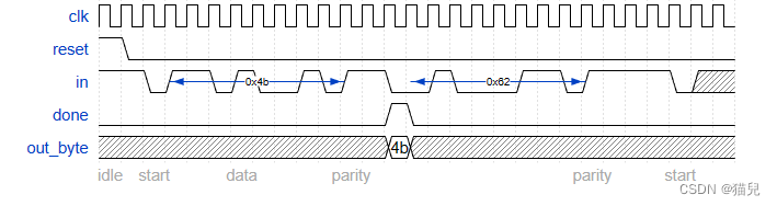
Note that the serial protocol sends the least significant bit first, and the parity bit after the 8 data bits.
Some timing diagrams
No framing errors. Odd parity passes for first byte, fails for second byte.
思路与代码
题目本身没有什么难度,但需要注意一些细节问题,给出我的状态转换图如下:
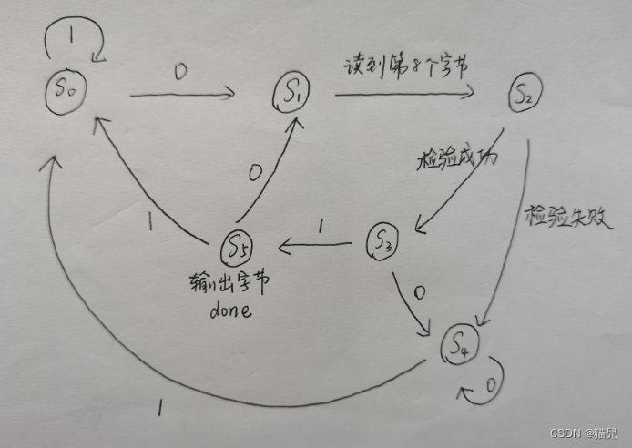
S 0 S_0 S0:等待开始的状态。
S 1 S_1 S1:接受字节状态(读8位)
S 2 S_2 S2:接受额外位(读1位)
S 3 S_3 S3:检验成功后,进入该状态
S 4 S_4 S4:检验失败后,进入该状态
S 5 S_5 S5:检验到停止位,从 S 3 S_3 S3进入到 S 5 S_5 S5,并输出字节,拉高done
具体细节,见代码注释。
module top_module(
    input clk,
    input in,
    input reset,    // Synchronous reset
    output [7:0] out_byte,
    output done
);

localparam[2:0]    //6个状态
s0 = 3'b000,
s1 = 3'b001,
s2 = 3'b010,
s3 = 3'b011,
s4 = 3'b100,
s5 = 3'b101;

reg[2:0] cs,nst;    // 当前状态,下一个状态
reg[3:0] Count;     // 计数,读了多少位
wire odd;
reg temp;           //temp配合odd使用,odd全程在更新,temp记录在开始进入读取字节时那一刻的odd
reg [7:0] val;      // 输出

always@(posedge clk) begin
    if(reset) cs<=s0;
    else cs<=nst;
end

always@(*) begin
    // 状态转换,注意odd^temp^in为1表示检验成功,否则检验失败
    // Count==7时,表示在读第八个字节的时候,状态从S1到S2
    case(cs)
        s0: if(in==1'b1) nst = s0;
            else nst = s1;
        s1: if(Count==7) nst = s2;
            else nst = s1;
        s2: if((odd^temp)^in) nst = s3;
            else nst = s4;
        s3: if(in==1'b1) nst = s5;
            else nst = s4;
        s4: if(in==1'b0) nst = s4;
            else nst = s0;
        s5: if(in==1'b1) nst = s0;
            else nst = s1;
        default: nst = s0;
    endcase
end

always@(posedge clk) begin
    // 更新 Count
    if(reset) Count<=0;
    else begin
        if(cs==s1) begin
            Count <= Count+1'b1;
        end
        else begin
            Count <= 0;
        end

    end
end

always@(posedge clk) begin
    // 更新 val
    if(reset) val <= 0;
    else begin
        if(cs==s1) begin
            val[Count] <= in;
        end
    end
end

always@(posedge clk) begin
    // 更新 temp
    if(reset) temp <= 0;
    else if(cs==s0||cs==s5) temp <= odd;
end

always@(*) begin
    // 输出字节
    if(cs==s5) out_byte = val;
    else out_byte = 8'b00000000;
end

always@(*) begin
    // 拉高done
    if(cs==s5) done = 1'b1;
    else done = 1'b0;
end

parity yyh(clk,reset,in,odd);
endmodule


 697
697

 被折叠的 条评论
为什么被折叠?
被折叠的 条评论
为什么被折叠?
 到【灌水乐园】发言


