


基于 MoveIt 的三维圆弧路径规划是利用 MoveIt 这个运动规划框架来实现机器人在三维空间中沿着圆弧路径进行规划和执行的过程。通常情况下,路径规划是在机器人自由空间中进行的,目标是找到一条连续的轨迹,将机器人从起始点移动到目标点,同时满足运动学约束、碰撞检测和路径平滑性等要求。
三维圆弧路径规划的目标是生成一条近似于圆弧的路径,使得机器人能够以最优的方式在三维空间中移动。这种路径通常用于需要精确控制末端执行器轨迹的应用,如机械加工、焊接等。
前期回顾
接上篇文章基于moveit的机械臂路径规划接口函数,上期编写了在关节空间和笛卡尔空间的运动函数,包括(move_j,move_p,move_l,_move_c等),但是当时的move_c函数,只能通过给定一个半径,再基于机械臂当前位置画一个二维空间下的圆周,代码如下。
bool move_c(double radius)
{
    geometry_msgs::Pose start_pose = arm.getCurrentPose().pose;
    std::vector<geometry_msgs::Pose> waypoints;
    waypoints.push_back(start_pose);

    //在x,y平面内生成圆周路点位姿
    double a=  start_pose.position.x;
    double b = start_pose.position.y;

    for(double th=0.0; th<6.28; th=th+0.01)
    {
        start_pose.position.x = a + (radius - radius * cos(th));
        start_pose.position.y = b + radius * sin(th);
        waypoints.push_back(start_pose);
    }
    // //在y,z平面内生成圆周路点位姿
    // double a=  start_pose.position.y;
    // double b = start_pose.position.z;
    // for(double th=0.0; th<6.28; th=th+0.01)
    // {
    //     start_pose.position.z = b + (radius - radius * cos(th));
    //     start_pose.position.y = a + radius * sin(th);
    //     waypoints.push_back(start_pose);
    // }
    // //在x,z平面内生成圆周路点位姿
    // double a=  start_pose.position.x;
    // double b = start_pose.position.z;
    // for(double th=0.0; th<6.28; th=th+0.01)
    // {
    //     start_pose.position.z = b + radius * sin(th);
    //     start_pose.position.x = a + (radius - radius * cos(th));
    //     waypoints.push_back(start_pose);
    // }

    // 设置末端的规划时间
    arm.setPlanningTime(10.0);

    moveit_msgs::RobotTrajectory trajectory;
    const double jump_threshold = 0.0;
    const double eef_step = 0.01;
    double fraction = 0.0;
    int maxtries = 100;
    int attempts = 0;

    while (fraction < 1.0 && attempts < maxtries)
    {
        fraction = arm->computeCartesianPath(waypoints, eef_step, jump_threshold, trajectory);
        attempts++;
    }

    if (fraction == 1)
    {
        ROS_INFO("Move_C Path computed successfully. Moving the arm.");


        moveit::planning_interface::MoveGroupInterface::Plan plan;
        plan.trajectory_ = trajectory;

        arm.execute(plan);
        sleep(1);
        arm.setPlanningTime(5.0);
        return true;
    }
    else
    {
        ROS_INFO("Move_C Path planning failed with only %0.6f success after %d attempts.", fraction, maxtries);
        return false;
    }

}
规划结果如下图所示,可以看出这种规划生成的路径有几个缺点:1、只能通过给定的半径画一个圆周;2、只能在两个维度的平面进行规划。
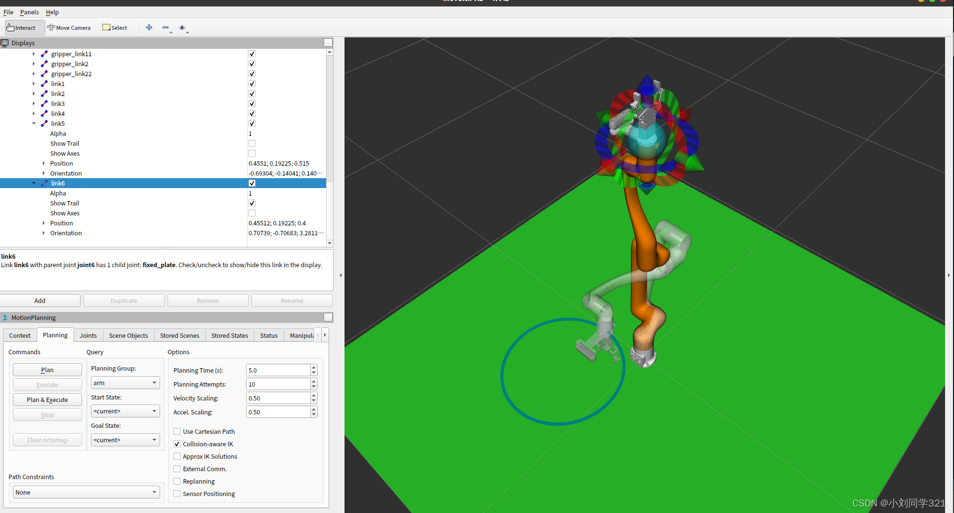
三维圆弧路径规划
三维圆弧路径规划要求我们通过给定的目标点和中间点以及机械臂当前的初始位置,确定一条圆弧,然后根据圆弧计算出路径点,实现机械臂的圆弧运动。
这里我们需要解决几个问题:
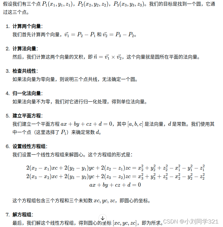
1、怎么通过给定的三个三维点确定圆心;
2、怎么确定圆弧对应圆的半径(这一步,只要得到圆心就很容易算出);
3、怎么确定圆弧的圆心角。
#怎么确定确定圆心 ?
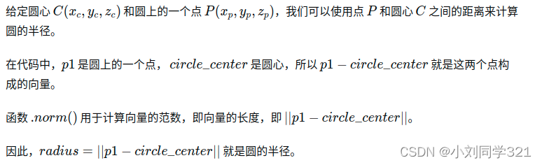
#怎么确定确定半径 ?
#怎么确定圆心角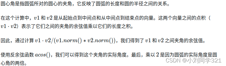
#怎么根据圆弧确定路点
#完整代码
bool move_c(const geometry_msgs::Pose& mid_pose, const geometry_msgs::Pose& end_pose)
{
geometry_msgs::Pose start_pose = arm.getCurrentPose().pose;
// 将geometry_msgs::Pose转换为Eigen::Vector3d
Eigen::Vector3d p1(start_pose.position.x, start_pose.position.y, start_pose.position.z);
Eigen::Vector3d p2(mid_pose.position.x, mid_pose.position.y, mid_pose.position.z);
Eigen::Vector3d p3(end_pose.position.x, end_pose.position.y, end_pose.position.z);
// 计算两个向量
Eigen::Vector3d v1 = p2 - p1;
Eigen::Vector3d v2 = p3 - p2;
// 计算v1和v2的叉积,得到法向量
Eigen::Vector3d normal = v1.cross(v2);
// 检查法向量是否为零向量(即三点共线)
if (normal.isZero()) {
// 三点共线,不能确s定一个圆
ROS_INFO("三点共线,无法确定圆");
return false;
}
// 归一化法向量
normal.normalize();
// 建立平面方程 ax + by + cz + d = 0, 其中 [a, b, c] 是法向量, d 是常数
double d = -(normal.dot(p1)); // 使用点p1来确定d
// 设置方程组 A*x = b 来解圆心
// 圆心满足 |C-P1| = |C-P2| = |C-P3|, 其中C是圆心, P1, P2, P3是给定的点
// 这可以转化为以下线性方程组:
// 2(x2-x1)xc + 2(y2-y1)yc + 2(z2-z1)zc = x2^2 + y2^2 + z2^2 - x1^2 - y1^2 - z1^2
// 2(x3-x2)xc + 2(y3-y2)yc + 2(z3-z2)zc = x3^2 + y3^2 + z3^2 - x2^2 - y2^2 - z2^2
// 加上平面方程 ax + by + cz + d = 0, 我们有三个方程来解三个未知数 xc, yc, zc
Eigen::Matrix3d A;
Eigen::Vector3d b;
A(0, 0) = 2 * (p2.x() - p1.x());
A(0, 1) = 2 * (p2.y() - p1.y());
A(0, 2) = 2 * (p2.z() - p1.z());
b(0) = p2.squaredNorm() - p1.squaredNorm();
A(1, 0) = 2 * (p3.x() - p2.x());
A(1, 1) = 2 * (p3.y() - p2.y());
A(1, 2) = 2 * (p3.z() - p2.z());
b(1) = p3.squaredNorm() - p2.squaredNorm();
A(2, 0) = normal.x();
A(2, 1) = normal.y();
A(2, 2) = normal.z();
b(2) = -d;
// 解方程组
Eigen::Vector3d circle_center = A.colPivHouseholderQr().solve(b);
// 计算半径
double radius = (p1 - circle_center).norm();//用p2和p3也行
// 计算圆心角
double angle = 2 * acos(v1.dot(v2) / (v1.norm() * v2.norm()));
ROS_INFO("circle_center:(%f,%f,%f)",circle_center[0],circle_center[1],circle_center[2]);
ROS_INFO("radius = %f, angle = %f", radius, angle);
// 设置圆弧路点位姿
std::vector<geometry_msgs::Pose> waypoints;
// for(double th=0.0; th<angle; th=th+0.01)
// {
// geometry_msgs::Pose temp_pose;
// temp_pose.position.x = circle_center[0] + radius * cos(th);
// temp_pose.position.y = circle_center[1] + radius * sin(th);
// temp_pose.position.z = start_pose.position.z;// 保持z坐标不变,在xy平面内
// temp_pose.orientation = start_pose.orientation;// 假设所有点的姿态相同
// waypoints.push_back(temp_pose);
// }
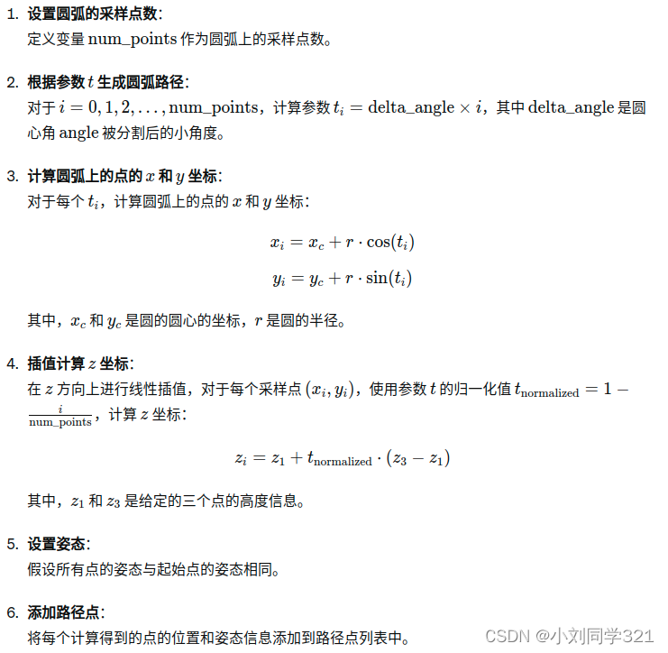
// 设置圆弧的采样点数
int num_points = 100;
double delta_angle = angle / num_points;
// 根据参数t生成圆弧路径
for (int i = 0; i <= num_points; ++i)
{
double t = delta_angle * i;
geometry_msgs::Pose temp_pose;
temp_pose.position.x = circle_center[0] + radius * cos(t);
temp_pose.position.y = circle_center[1] + radius * sin(t);
// 根据给定的三个点的高度来插值计算z坐标
double t_normalized = static_cast<double>(num_points - i) / num_points;
temp_pose.position.z = p1.z() + t_normalized * (p3.z() - p1.z()); // 在z方向上插值变化
// 假设所有点的姿态相同,你也可以修改这里来设置不同的姿态
temp_pose.orientation = start_pose.orientation;
waypoints.push_back(temp_pose);
}
//waypoints逆序
reverse(waypoints.begin(), waypoints.end());
// 设置终端的规划时间
arm.setPlanningTime(10.0);
moveit_msgs::RobotTrajectory trajectory;
const double jump_threshold = 0.0;
const double eef_step = 0.01;
double fraction = 0.0;
int maxtries = 100;
int attempts = 0;
while (fraction < 1.0 && attempts < maxtries)
{
fraction = arm->computeCartesianPath(waypoints, eef_step, jump_threshold, trajectory);
attempts++;
}
if (fraction == 1)
{
ROS_INFO("Move_C Path computed successfully. Moving the arm.");
moveit::planning_interface::MoveGroupInterface::Plan plan;
plan.trajectory_ = trajectory;
arm.execute(plan);
sleep(1);
arm.setPlanningTime(5.0);
return true;
}
else
{
ROS_INFO("Move_C Path planning failed with only %0.6f success after %d attempts.", fraction, maxtries);
return false;
}
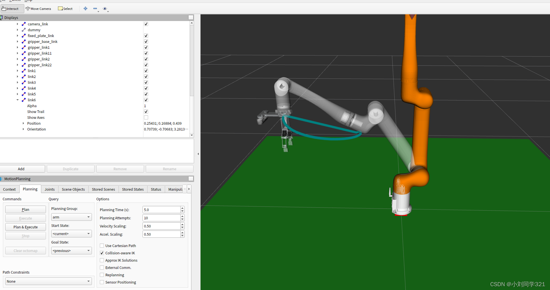
}规划结果如下图所示。可以看出它是在三维空间下生成的一段圆弧轨迹。


 9446
9446


 被折叠的 条评论
为什么被折叠?
被折叠的 条评论
为什么被折叠?
 到【灌水乐园】发言


