


前言
verilog中的generate块可以称为生成块,所谓生成,可以理解为复制。如果不太好理解,下面我们继续使用generate块。
generate块应用的场合通常是对模块进行批量例化,或者有条件的例化,使用参数进行控制对哪些模块进行例化,或者例化多少。
不仅限于模块例化,当同一个操作或模块实例需要多次重复,或者某些代码需要根据给定的Verilog参数有条件地包含时,这些语句特别方便。
generate块可以分为generate for和generate if或者generate case。
正文
下面根据实际例子对这几个generate块语句进行分析。
generate for
先设计一个半加器:
// Design for a half-adder
module ha ( input   a, b,
            output  sum, cout);

  assign sum  = a ^ b;
  assign cout = a & b;
endmodule
下面对半加器模块例化N次,N为输入变量的位宽,例如:
input [N-1:0] a, b;
每一次对输入变量的一位进行加法运算。
如下:
// A top level design that contains N instances of half adder
module my_design
	#(parameter N=2)
		(	input [N-1:0] a, b,
			output [N-1:0] sum, cout);

	// Declare a temporary loop variable to be used during
	// generation and won't be available during simulation
	genvar i;

	// Generate for loop to instantiate N times
	generate
		for (i = 0; i < N; i = i + 1) begin
          ha u0 (a[i], b[i], sum[i], cout[i]);
		end
	endgenerate
endmodule
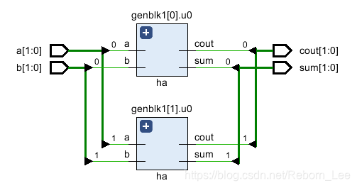
a[0]和b[0]的输出sum[0]和cout[0],而a[N-1]和b[N-1]的输出sum[1]和cout[1]。
对应的RTL图可想而知,就是多个半加器的复制。
如果N = 2,则为:
generate if
generate if中的条件必须是参数,这是很重要的一点,初学者容易误用,例如将generate if(),括号内给一个变量,根据其值选择执行哪一块语句。
下面设计一个仅用于仿真的例子:
我们先设计两个待选择模块:
// Design #1: Multiplexer design uses an "assign" statement to assign
// out signal
module mux_assign ( input a, b, sel,
                   output out);
  assign out = sel ? a : b;

  // The initial display statement is used so that
  // we know which design got instantiated from simulation
  // logs
  initial
  	$display ("mux_assign is instantiated");
endmodule
// Design #2: Multiplexer design uses a "case" statement to drive
// out signal
module mux_case (input a, b, sel,
                 output reg out);
  always @ (a or b or sel) begin
  	case (sel)
    	0 : out = a;
   	 	1 : out = b;
  	endcase
  end

  // The initial display statement is used so that
  // we know which design got instantiated from simulation
  // logs
  initial
    $display ("mux_case is instantiated");
endmodule
下面使用generate if语句来选择例化哪一个模块:
// Top Level Design: Use a parameter to choose either one
module my_design (	input a, b, sel,
         			output out);
  parameter USE_CASE = 0;

  // Use a "generate" block to instantiate either mux_case
  // or mux_assign using an if else construct with generate
  generate
  	if (USE_CASE)
      mux_case mc (.a(a), .b(b), .sel(sel), .out(out));
    else
      mux_assign ma (.a(a), .b(b), .sel(sel), .out(out));
  endgenerate

endmodule
USE_CASE就是一个参数,根据参数的值来选择例化哪一个模块。
设计仿真文件来验证:
module tb;
	// Declare testbench variables
  reg a, b, sel;
  wire out;
  integer i;

  // Instantiate top level design and set USE_CASE parameter to 1 so that
  // the design using case statement is instantiated
  my_design #(.USE_CASE(1)) u0 ( .a(a), .b(b), .sel(sel), .out(out));

  initial begin
  	// Initialize testbench variables
  	a <= 0;
    b <= 0;
    sel <= 0;

    // Assign random values to DUT inputs with some delay
    for (i = 0; i < 5; i = i + 1) begin
      #10 a <= $random;
      	  b <= $random;
          sel <= $random;
      $display ("i=%0d a=0x%0h b=0x%0h sel=0x%0h out=0x%0h", i, a, b, sel, out);
    end
  end
endmodule
上面仿真文件中将USE_CASE代入参数为1,因此,应该例化的是mux_case 被执行。
// When USE_CASE = 1
ncsim> run
mux_case is instantiated
i=0 a=0x0 b=0x0 sel=0x0 out=0x0
i=1 a=0x0 b=0x1 sel=0x1 out=0x1
i=2 a=0x1 b=0x1 sel=0x1 out=0x1
i=3 a=0x1 b=0x0 sel=0x1 out=0x0
i=4 a=0x1 b=0x0 sel=0x1 out=0x0
ncsim: *W,RNQUIE: Simulation is complete.
generate case
generate case语句和generate if语句用法无异,和普通的if与case一致,if具有优先级,case没有优先级。
举个例子,介绍其使用方法。
先设计一个半加器:
// Design #1: Half adder
module ha (input a, b,
           output reg sum, cout);
  always @ (a or b)
  {cout, sum} = a + b;

  initial
    $display ("Half adder instantiation");
endmodule
在设计一个全加器:
// Design #2: Full adder
module fa (input a, b, cin,
           output reg sum, cout);
  always @ (a or b or cin)
  {cout, sum} = a + b + cin;

    initial
      $display ("Full adder instantiation");
endmodule
设计顶层模块,令参数为ADDER_TYPE = 1;则如下:
// Top level design: Choose between half adder and full adder
module my_adder (input a, b, cin,
                 output sum, cout);
  parameter ADDER_TYPE = 1;

  generate
    case(ADDER_TYPE)
      0 : ha u0 (.a(a), .b(b), .sum(sum), .cout(cout));
      1 : fa u1 (.a(a), .b(b), .cin(cin), .sum(sum), .cout(cout));
    endcase
  endgenerate
endmodule
设计仿真文件:
module tb;
  reg a, b, cin;
  wire sum, cout;

  my_adder #(.ADDER_TYPE(0)) u0 (.a(a), .b(b), .cin(cin), .sum(sum), .cout(cout));

  initial begin
    a <= 0;
    b <= 0;
    cin <= 0;

    $monitor("a=0x%0h b=0x%0h cin=0x%0h cout=0%0h sum=0x%0h",
             a, b, cin, cout, sum);

    for (int i = 0; i < 5; i = i + 1) begin
      #10 a <= $random;
      b <= $random;
      cin <= $random;
    end
  end
endmodule
可见,代入参数为0,应该例化的为半加器模块:
ncsim> run
Half adder instantiation
a=0x0 b=0x0 cin=0x0 cout=00 sum=0x0
a=0x0 b=0x1 cin=0x1 cout=00 sum=0x1
a=0x1 b=0x1 cin=0x1 cout=01 sum=0x0
a=0x1 b=0x0 cin=0x1 cout=00 sum=0x1
ncsim: *W,RNQUIE: Simulation is complete.
参考资料
本系列博文
Verilog初级教程(11)Verilog中的initial块
Verilog初级教程(10)Verilog的always块
Verilog初级教程(8)Verilog中的assign语句
Verilog初级教程(7)Verilog模块例化以及悬空端口的处理
Verilog初级教程(5)Verilog中的多维数组和存储器
Verilog初级教程(2)Verilog HDL的初级语法
FPGA/ASIC初学者应该学习Verilog还是VHDL?
- 个人微信公众号: FPGA LAB


 2万+
2万+


 被折叠的 条评论
为什么被折叠?
被折叠的 条评论
为什么被折叠?
 到【灌水乐园】发言


