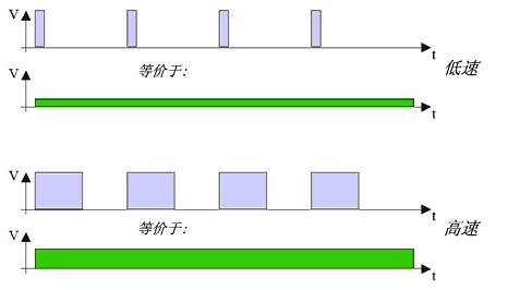
目前机器人的电机大多采用脉宽调制(Pulse width modulation)或简称PWM进行控制,而不是使用模拟功率电路。在软件中通过改变脉冲宽度(如图1,上图对下图),我们可以改变等效的模拟电机信号,从而达到控制电机转速的目的。电机系统的行为就像是一个积分器,在一定时间的范围内对数字信号进行积分。而 则称为占空比。

图1 PWM
问题1 电机控制的非线性
比较遗憾的是,通常情况下,电机所产生的速度与PWM信号比并非是线性关系,如图2是我们对轮式驱动单元进行实验的结果,而图3右图则是我们查阅得到的Faulhaber 2230电机的测量曲线,图3左图是电机的阶跃响应。由于实验的电机的减速箱和速度的单位的不同,图2、3所得到的具体数值不尽相同,但它们却共同反映了电机PWM控制的一个特性——非线性!

图2 轮式单元车轮转速(周每秒)/PWM

图3 Faulhaber 2230电机的阶跃响应与速度/PWM比
问题2 开环控制的不准确
通常电机可以实现正/反转、速度调节。但是,我们却并不知道电机实际的运行速度。应当注意到电机的实际运行速度并不仅仅只与输入的PWM信号有关,还会受到例如负载(例如机器人的重量或是驱动区域的倾斜程度)等外部因素的影响。如果使用开环控制的话,在低速情况下,电机的扭矩通常也非常的小。
解决方法 增加PID控制
电机增加编码盘后,便为闭环控制的实现提供了物质基础。但仅仅是简单的反馈是不够的,简单的比例P反馈控制利用误差进行校正,而误差却是始终存在的(只是能将控制在有限的范围内),若想实现零稳态误差响应,还需要增加一个积分I环节。如果想进一步提高机器人的灵敏度(动态响应性能)还可以增加一个微分环节D,这样便可以组成一个PID控制器。但在这里不建议大家使用微分D环节,因为稍有不慎便有可能造成振荡,而在此应用中D环节对性能的提升也十分有限。下面我们介绍一下我们编写的程序。
PID控制程序
注:我们是在Arduino下进行的开发,但此程序进行简单的修改便可移植到任何类型的单片机上。
1、连接接口针号设置
A、B、C分别表示三个不同的轮式单元,ctrl_1、ctrl_2、ctrl_3表示三个电机控制线,counter是编码盘输入,analog是电机电流检测(用于观测电机是否堵转,当读数超过532并持续一段时间时,表示堵转,应及时断开电机以避免烧毁)
|
01
02
03
04
05
06
07
08
09
10
11
12
13
14
15
|
const
int
A_ctrl_1=3;
//PWM OUT
const
int
A_ctrl_2=4;
//Motor control 2
const
int
A_ctrl_3=12;
//Motor control 3
const
int
A_counter= 2;
//Motor counter input
const
int
A_analog = 0;
//Motor current measure input
const
int
B_ctrl_1=5;
//PWM OUT
const
int
B_ctrl_2=4;
//Motor control 2
const
int
B_ctrl_3=12;
//Motor control 3
const
int
B_counter= 19;
//Motor counter input
const
int
B_analog = 4;
//Motor current measure input
const
int
C_ctrl_1=6;
//PWM OUT
const
int
C_ctrl_2=7;
//Motor control 2
const
int
C_ctrl_3=8;
//Motor control 3
const
int
C_counter= 20;
//Motor counter input
const
int
C_analog = 5;
//Motor current measure input
|
2、主要参数设置
Kp为比例值,我们设为1,通常越大调节速度越快,代价是有可能出现超调,或超调过大甚至是不稳定。Ki是积分项,我们设为4.
|
01
02
03
04
05
06
07
08
09
10
|
/you can chane the following const paramters
const
int
CURRENT_LIMIT=530;
// high current warning, if the value of Motor curren is bigger than CURRENT_LIMIT more than 10 sample, stop.
const
int
NUM_C=200;
//the number of counter of a roll.
//IF select CHANGE in attachInterrupt(0, rencoder, CHANGE) ,the NUM_C should be multiple by 2
//Other selection in attachInterrupt(0, rencoder, FALLING), the NUM_C is equal to the number of counter of a roll
const
int
LOOPTIME =50;
//the loop time(ms) of PID control
float
Kp=1;
// PID proportional control gain
float
Ki=4;
// PID i control gain
const
float
K_modal=1;
// K_modal is the modal number of motor. it is eaual 255/(the full RPS of motor). RPS is roll per second
///
|
3、PI控制程序
我们首先需要将码盘连接至一个中断,每来一次中断便counter++。当中断设为FALLING或RISING时NUM_C设为100,因为码盘100个齿每转一周产生100个FALLING中断。当中断设为CHANGE时,则是NUM_C设为200,因为码盘100个齿每转一周产生200个CHANGE中断。然后我们通过记录一个周期looptime内counter的增加数便可得到实际的转动速度(转/秒),如下。
|
1
|
speed_act=
float
(count- count_fomer)*1000/
float
(looptime*NUM_C);
|
误差项为期望速度(转/秒)减去实际速速。
|
1
|
error =
abs
(desire_act) -
abs
(speed_act);
|
PID控制量如下:
|
1
|
pidTerm = Kp * error + Kp * Ki * (error +last_I);
|
更新积分值,注意last_I应使用静态变量,以不断积分。
|
1
|
last_I = error + last_I;
|
PI完整代码如下,我们的代码非常简单,关键的只有几行(便于学习),并且在经过了实际的测试,即使在低速的情况下仍能保持较大的力矩,无论上坡还是下坡均能保持指定的速度巡航。我们发现在Arduino论坛里有一个PID类(附件中),感兴趣的读者可以拿来研究使用一下。
|
01
02
03
04
05
06
07
08
09
10
11
12
13
14
15
16
17
18
19
20
21
22
23
24
25
26
27
28
29
|
float
PID_updata(
float
command,
float
targetValue,
float
currentValue)
//computePWM value
{
float
pidTerm = 0;
// PID correction
float
error=0;
static
float
last_I=0;
error =
abs
(targetValue) -
abs
(currentValue);
pidTerm = Kp * error + Kp * Ki * (error + last_I);
last_I = error + last_I;
return
pidTerm;
}
int
control_loop(
int
looptime ,
float
speed_req,
int
PWM_val)
{
long
lastMilli;
long
count_fomer;
float
speed_act;
lastMilli=millis();
count_fomer=count;
interrupts();
while
((millis()-lastMilli) <= looptime)
{ ; }
// enter tmed loop
noInterrupts();
speed_act=
float
(count- count_fomer)*1000/
float
(looptime*NUM_C);
PWM_val= PID_updata(PWM_val, speed_req, speed_act);
// compute PWM
return
constrain(PWM_val, 0, 255);
}
//
|


 1292
1292

 被折叠的 条评论
为什么被折叠?


